Journal of Chemical and Pharmaceutical Research, 2014, 6(7): 2414-2421
Research Article
CODEN(USA) : JCPRC5
ISSN : 0975-7384
Analysis on static characteristics of linear rolling guide under
tangential load
Wang Jian Hua, Ma Tong Min, Liu Zhi Feng and Zhao Yong Sheng
College of Mechanical Engineering and Applied Electronics Technology, Beijing University of Technology,
Beijing, China
_____________________________________________________________________________________________
ABSTRACT
Linear Rolling Guide not only bears normal load, but also tangential load when it is used actually. On the basis of Hertz Contact Theory, this essay firstly analyses the situation that the LR Guide bears tangential light load with four lines of balls. When the external load further increases, the essay analyses the situation that the guide bears heavy load with only two lines of balls, and perfects the tangential static stiffness model of the LR Guide. On the basis of it, aiming at the deficiency that the previous model just considered the balls’ elastic deformation, the essay put out a tangential static stiffness model of the LR Guide which considered the deformation of the rail, and the validity of the model is verified by experiment. At last, the essay studies the influences of preload and groove fitness on the tangential stiffness of LR Guide, providing the basis of choosing parameters when chooses LR Guide.
Key words: linear rolling guide, Hertz contact, tangential load, contact stiffness, stiffness experiment
_____________________________________________________________________________________________
INTRODUCTION
As a precision transmission component, linear rolling guide is the key part of CNC machine tool. The accuracy of CNC is influenced directly by the mechanical performance and the characteristics of LR Guide. Studies show that the 30%~50% static stiffness of machine tool depends on the stiffness properties of joint surface, moreover, the influence of mechanical structure joint surface damping is more obvious. Compared to LR guides supported by non-contact bearings such as air bearings requiring complex and expensive fabrication processes, LR Guide using balls bearings have advantages such as high stiffness, relatively good reliability, and low cost[1]. In the LR Guide, force transferred between the carriage and rail is performed via balls. During implementation, a LR Guide is usually pre-stressed between the balls and the carriage/rail. It mainly composed of slider, rail and balls. The balls are rolling cycle around the slider and the rail to achieve the relative motion of them, as shown in Fig.1.
At present, the research on LR Guide static characteristic, mainly concentrated the situation that the guide bears light load with four lines of balls [2-4]. Literature [2] used two spring-damper element simulate a line of balls, established five dynamic equations, solved the modal parameters, and the validity of the model is verified by experiment. On the basis of literature [2], literature [3] used spring-damper element simulate all of the balls, established the equation by energy theory, on the basis of the equation, used Lagrange equation establish five dynamic equations. The above literatures simplified the balls, mainly concentrated the situation that the guide bears light load with four lines of balls, didn’t consider the situation that the guide bears heavy load with two lines of balls.
Aiming at the deficiency that the previous model just considered the situation that the guide bears tangential light load with four lines of balls, this essay firstly analyses the situation that the guide bears tangential light load with four lines of balls. When the external load further increase, the essay analyses the situation that the LR Guide bears heavy load with only two lines of balls, and perfects the tangential static stiffness model of LR Guide. Aiming at the deficiency that the previous model just considered the elastic deformation of balls, the essay put out a tangential static stiffness model of the guide which considered the deformation of the rail, and the validity of the model is verified by experiment. On the basis of the model, the essay studies the influences of preload and groove fitness on the tangential stiffness of LR Guide, providing the basis of choosing parameters when chooses linear rolling guide.
Fig. 1: LR Guide Fig. 2: LR Guide bears tangential load
EQUILIBRIUM EQUATION OF SLIDER
According to the Manual of Design and Application of Rolling Bearing (Huazhong institute of technology press, 1985), the relationship between the force and deformation of the single ball can be obtained by the Hertz contact theory:
(
)
3
3 2
2
3 2 2 1
1 2
2 2
1 2
2 2
1-
1-3
2
h
F
k
v
v
E
E
α
α
µ
ρ
=
=
(
+
)
∑
(1)
Further, we can get the relationship of the single ball’s stiffness and deformation: 1
2
3
2
hK
=
k
α
[image:2.595.249.453.489.659.2]
(2)
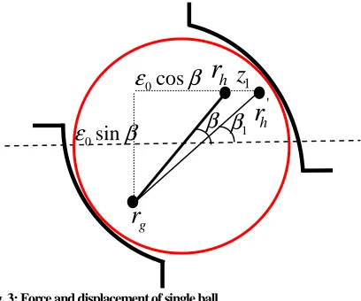
Fig. 3: Force and displacement of single ball
Among them:
α
is the elastic deformation of a single ball;F
is the external load;µ
is the hertz coefficient;E
1、1
v
、2
E
、2
v
are respectively Elastic Modulus and Poisson ratio of the rail and slider;∑
ρ
is the sum of curvature. As can be seen from the above Eq. (2), the single ball’s stiffness is connected with the deformation, so, it isn’t a linear system.In the LR Guide system, balls are contacted with the rail and slider’s groove, when the LR Guide bears tangential 0
cos
ε
β
r
h'
h
r
0
sin
ε
β
g
r
1
β
β
1
z
1
α
1
α
2
α
2
α
Tangential Load slider rail
as shown in Fig.3. Among them,
r
his the initial curvature center of loaded slider;r
h'is the new curvature center ofloaded slider;
r
gis the curvature center of rail groove;β
represents the initial contact angle;β
1represents thenew contact angle. Now we use the distance of the slider and rail’s center of curvature (two radius of curvature is equal) to represent the elastic deformation of the balls,
According to Fig.3, the initial distance between the slider and rail’s center of curvature is:
(
)
0
2
f
1
D
ε
=
−
(3)
Among them:
f
is fitness of the groove;D
is diameter of the ball.LR Guide use the way that increase balls diameter to get preload, and assuming that the balls have the pre-compression
∆
. When the LR Guide’s displacementz
1≤
z
0 (the critical displacement of four lines of ballsbearing and two lines of balls bearing), the distance
ε
zof left two lines of balls become:(
) (
2)
21 0
cos
z
1 0sin
ε
=
ε
β
+
+
ε
β
(4)
The new contact angle become:
0 1
0 1
sin
arctan(
)
cos
z
ε
β
β
ε
β
=
+
(5)The elastic deformation of the left two lines of balls are:
1 1 0
α ε ε
= − + ∆
(6)In the same way, we can get the right two lines of balls’ elastic deformation and the new contact angle:
(
) (
2)
22 0
cos
z
1 0sin
0α
=
ε
β
−
+
ε
β
− + ∆
ε
(7)
0 2
0 1
sin
arctan(
)
cos
z
ε
β
β
ε
β
=
−
(8)According to Fig.2, we can get the force equilibrium equation of the slider:
3 3
2 2
1 1 2 2
2 cos
n
β α
(
k
h) 2 cos
−
n
β
(
k
hα
)
=
P
(9)Among them,
P
is the external load,n
is the number of the ballsWhen the elastic deformation of right two lines of balls are zero, the LR Guide is only by two lines left two lines of balls bearing, the force equilibrium equation of the slider is:
3 2
1 1
2 cos
n
β α
(
k
h)
=
P
(10)
The above analysis establishes the contact model of LR Guide with preload.
TANGENTIAL STIFFNESS MODEL OF LR GUIDE CONSIDERED RAIL DEFORMATION
When LR Guide bears tangential load, the rail’s deformation is important for the LR Guide’s tangential displacement, its deformation isn’t neglect. According to the rail’s bearing conditions and deformation state, we simplified it as
cantilever beam. The resultant force of upper lines of balls’
F
11andF
12 isF
1, the resultant force of lower lines ofFig. 4: Simplified rail
Assuming that rail section moment of inertia is I, the grooves deformation of upper and lower are:
3 2
1 1 2 2 1
1 1 2
(
)
(2
3 )
3
6
F l
l
F l
l
l
EI
EI
δ
=
+
+
+
(11)2 3
1 1 2 1
2
(2
13 )
26
3
F l
F l
l
l
EI
EI
δ
=
+
+
(12)According to the rail’s bearing conditions, we can get:
1 2
2
P
F
=
F
=
(13)
Taking Eq.(13) into (11)(12), we can get:
3 3 2
1 2 1 1 2
1
2 (
)
(2
3
)
12
P l
l
P
l
l l
EI
δ
=
+
+
+
(14)
3 2
1 1 2
2
4
3
12
Pl
Pl l
EI
δ
=
+
(15)We can get the force and deformation of the rail while simplified as cantilever beam, according to Fig.4, the deformation of the slider’s center because of rail deformation is:
1 2
2
2
z
=
δ δ
+
(16)
Assuming that the total deformation is
z
:1 2
z
= +
z
z
(17)Among them,
3 2 3 3 2
1 1 2 1 2 1 1 2
2
4
3
2 (
)
(2
3
)
24
Pl
Pl l
P l
l
P
l
l l
z
EI
+
+
+
+
+
=
(18)Taking (18) into (17),
3 2 3 3 2
1 1 2 1 2 1 1 2
1
4
3
2 (
)
(2
3
)
24
Pl
Pl l
P l
l
P
l
l l
z
z
EI
+
+
+
+
+
= −
(19)So, we get
z
1=
f z P
( , )
, take it into (6)(7),[
]
2 21 0
cos
f z P
( , )
(
0sin
)
0α
=
ε
β
+
+
ε
β
− + ∆
ε
(20)[
]
2 22 0
cos
f z P
( , )
(
0sin
)
0α
=
ε
β
−
+
ε
β
− + ∆
ε
(21)Taking (20)(21) into the force equilibrium equation of the slider:
1
F
22
F
F
21
l
2
l
δ
221
F
11
F
12
(
)
3 3
2 2
1 1 2 2 1 0
2 cos
n
β
(
k
hα
) 2 cos
−
n
β
(
k
hα
)
=
P z
≤
z
(22)(
)
3 2
1 1 1 0
2 cos
n
β
(
k
hα
)
=
P
z
≥
z
(23)EXPERIMENTAL SECTION
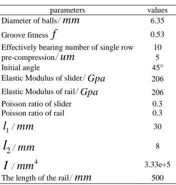
The following calculate force and displacement relationship when LR Guide with preload and without preload. LR Guide characteristic parameters are shown in table 1:
Table1 LR Guide parameters
parameters values
Diameter of balls/
mm
6.35Groove fitness
f
0.53Effectively bearing number of single row 10
pre-compression/
um
5Initial angle 45°
Elastic Modulus of slider/Gpa 206
Elastic Modulus of rail/Gpa 206
Poisson ratio of slider 0.3
Poisson ratio of rail 0.3
1
l
/mm
302
l
/mm
8I
/4
mm
3.33e+5The length of the rail/
mm
500According to table 1, the ball diameter is 6.35, the groove fitness is 0.53, according to the Manual of Design and Application of Rolling Bearing (Huazhong institute of technology press, 1985), we can get the sum of curvature
ρ
∑
and main curvature functionF
( )
ρ
:1
4
1
0.3327
f
mm
fD
ρ
=
−
=
−∑
(24)
1
( )
0.892
4
1
F
f
ρ
=
=
−
(25)According to the
F
( )
ρ
=
0.892
, we can getµ
=
0.695
, the calculation result is shown in Fig.6. [image:5.595.220.396.210.395.2]In order to prove the validity of the model, we conduct an experiment. The experimental device is shown in figure 5. The LR Guide is connected with experimental stage by bolts, use the strength bolt to apply load. Load and displacement can be read by the pressure sensor and dial gauge, the result is shown in figure 6.
Fig. 5: Tangential stiffness experiment Dial gauge Pressure sensor
Strength bolt
①Force and displacement curve of LR Guide without considered rail’s deformation ②Force and displacement curve of LR Guide considered rail’s deformation
③Force and displacement curve of LR Guide experiment ④Force and displacement curve of LR Guide without preload
Fig. 6: Force and displacement curve of experiment and calculation
As can be seen from the above, calculation results is consist with experimental results, the model’s validity is verified. The force and displacement curve of the LR guide is straight in the early stage, stiffness is constant. Compare curve ③ and curve ④,the stiffness of model considered rail’s deformation is lower than the model
without considered rail’s deformation, the curve 3 is more consist with experimental results.
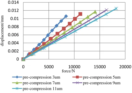
Fig. 7: Force and displacement curve of different preload
DISCUSSION OF PARAMETERS ON TANGENTIAL STIFFNESS
LR Guide parameters are crucial to select the LR Guide reasonably. This paper studies the impaction of preload and groove fitness on LR Guide tangential static stiffens, and work out the curves of parameters and normal stiffness.
A INFLUENCE OF PRELOAD ON TANGENTIAL STIFFNESS
Now Select different preload (the fitness is 0.53), the curve of force and displacement is shown in figure 7.
As can be seen from the above, the curve of the force and displacement is approximately straight, so, we consider the stiffness as constant. To realize the influence of preload on stiffness, we give the curve of preload and normal stiffness, as shown in Fig 8:
0 0.005 0.01 0.015 0.02 0.025
0 5000 10000 15000 20000
ta
n
g
en
ti
al
d
is
p
la
ce
m
en
t/
m
m
force/N
①
②
③
④
0 0.002 0.004 0.006 0.008 0.01 0.012 0.014
0 5000 10000 15000 20000
d
is
p
la
ce
m
en
t/
m
m
force/N
[image:6.595.169.444.381.574.2]Fig.8: Preload and tangential stiffness curve
As can be seen from the above, the stiffness increase as the increase of preload. We verify the LR Guide is variable stiffness system again, and the growth rate constant decreases as the increase of preload. So, we can use the way that increase preload to increase the stiffness of LR Guide.
B INFLUENCE OF GROOVE FITNESS ON TANGENTIAL STIFFNESS
Now Select different groove fitness (pre-compression is 0.53), the curve of force and displacement is shown in Fig.9.
Fig.9: Force and displacement curve of different fitness
The curve of groove fitness and stiffness is shown in Fig.10.
Fig.10: Fitness and tangential stiffness curve
As can be seen from the above, the tangential stiffness decrease as the preload increase, the rate constant decreases as the increase of fitness. So, we can use the way that decrease the fitness to increase the stiffness of LR Guide.
8.0E+5 1.0E+6 1.2E+6 1.4E+6 1.6E+6
0.003 0.005 0.007 0.009 0.011
st
if
fn
es
s/
(N
/m
m
)
pre-compression/mm
0 0.002 0.004 0.006 0.008 0.01 0.012 0.014
0 5000 10000 15000 20000
st
if
fn
es
s
force/N
f=0.51 f=0.52 f=0.53 f=0.54
f=0.55
9.0E+5 1.0E+6 1.1E+6 1.2E+6 1.3E+6 1.4E+6 1.5E+6
0.51 0.52 0.53 0.54 0.55
st
if
fn
es
s/
(N
/m
m
)
CONCLUSION
On the basis of Hertz contact theory, this essay put out a tangential static stiffness model of LR Guide which considered the deformation of the rail, and the validity of the model is verified by experiment, include:
(1)Firstly analyses the situation that the LR Guide bears tangential light load with four lines of balls. When the external load further increases, this essay analyses the situation that LR Guide bears heavy load with only two lines of balls, and perfects the tangential static stiffness model of LR Guide.
(2)Aiming at the deficiency that the previous model just considered the balls’ elastic deformation, the essay put out a tangential static stiffness model of the guide which considered the deformation of the rail, and the validity of the model is verified by experiment.
(3)This essay studies the influences of preload and groove fitness on the tangential stiffness of guide, providing the basis of choosing parameters when chooses LR Guide.
Acknowledgments
The authors wish to thank the national 863 project《The key technology of design and manufacturing in precision
horizontal machining center》(SS2012AA040702), under which the present work was possible.
REFERENCES
[1]Hiwin Technologies Company, in: Hiwin linear rolling guide technical information, Hiwin Company, Taiwan, 2000.
[2]ZHANG Yaoman; LIU Chunshi; XIE Zhikun, Academic J.Manufacturing Technology & Machine Tool, 2007,
21(7), 75-78.
[3]Yi Y S; YY Kim, Academic J. Journal of Mechanical Science and Technology, 2008, 50-60.
[4]S James; Cheng Chang; Gent Tsai, Academic J. Journal of Mechanical Science and Technology, 2012, 26(3), 671-680.
[5]Shimizu S, Academic J. Journal of Mechanical Science and Technology, 1990, 56(8), 1445-1451. [6]Shimizu S, Academic J. Japan, 1998, 64(11):1573-1576.
[7]WU Wenxi; JIANG Dazhi, Academic J. Machinery Design and Manufacture, 2009, 24(5): 135-137. [8]Shimizu S; Saito E; Uchida H, Academic J. Tri-biology Transactions ,1998,41 (1) ,49-59.