TITLE
SMARTPHONE-BASED ROBOT CONTROL FOR LOCALISATION
NIK FIRDAUS BIN NIK MAHMOD
A project report submitted in partial fulfilment of the requirement for the award of the
Degree of Master of Electrical Engineering
Faculty of Electrical and Electronic Engineering Universiti Tun Hussein Onn Malaysia
v
ABSTRACT
ABSTRAK
vii
CONTENTS
TITLE i
DECLARATION ii
DEDICATION iii
ACKNOWLEDGEMENT iv
ABSTRACT v
ABSTRAK vi
CONTENTS vii
LIST OF TABLES ix
LIST OF FIGURES x
LIST OF ABBREVIATIONS xiii
LIST OF APPENDICES xiv
CHAPTER 1 INTRODUCTION 1
1.1 Background 1
1.2 Problem statement 3
1.3 Aim and objectives 4
1.4 Scope and limitation 4
CHAPTER 2 LITERATURE REVIEW 5
2.1 Introduction 5
2.2 Types of controller interface 5
2.3 The localisation strategies 8
CHAPTER 3 METHODOLOGY 13
3.1 Introduction 13
3.2 Flow Chart of the Project 13
3.2.1 Mobile Robot Design and Construction 15
3.2.2 The Android Programming Development 27
3.3 Summary 30
CHAPTER 4 RESULT AND DISCUSSION 31
4.1 Introduction 31
4.2 DC Motor Analysis 31
4.3 Robot Analysis 37
4.3.1 Network Provider Analysis 38
4.3.2 Robot Operator Analysis 42
4.4 Sensor Analysis 45
4.5 Robot Localisation Analysis 49
4.6 Summary 53
CHAPTER 5 CONCLUSION 54
5.1 Introduction 54
5.2 Mobile robot 54
5.3 Develop an Android application to control mobile
robot according to the DTMF signal. 54
5.4 Localisation performance of mobile robot 55
5.5 Conclusion 55
REFERENCES 56
APPENDIX A 58
APPENDIX B 59
ix
LIST OF TABLES
3.1: State diagram for SPG30E-30K model; (a) Clockwise Rotation,
(b) Counter Clockwise Rotation 17
3.2: The quadrature Hall Effect encoder attributes. 17
3.3:The MDD10A motor driver characteristics. 18
3.4: DTMF signal decode. 21
3.5: Smartphone specs comparison table. 26
3.6: List of sensors for Samsung Galaxy Note II model. 28
4.1: The keys assigned according to PWM 35
4.2: Comparison result of network provider. 39
4.3: Result comparison of robot operator 42
4.4: Error comparison between Operator A and B 43
4.5: Smartphone used features. 45
7.1: DC Motor (left) data analysis results 58
8.1: DC Motor (right) data analysis results 59
LIST OF FIGURES
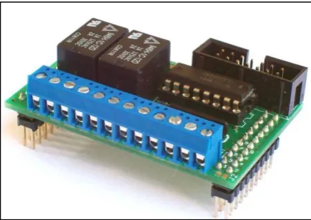
1.1: An IO board model MXD2R for Single Board Computer (SBC)
industrial application [2]. 2
2.1: System organization [4]. 6
2.2: The P3DX robot overall system [10]. 6
2.3: General layout of the system [11]. 7
2.4: General block diagram [7]. 7
2.5:Localization by concurrent observation of several geometric
beacons [13]. 8
2.6: The coded pattern that inspired the localization algorithm [16]. 9
2.7: Landmark colours made out of A4 cardboard coloured paper;
have 40 mm in radius and 210 mm in height [4]. 9
2.8: (a) Model of robot motion; (b) Model of location measurement [19]. 10
2.9: System layout diagram for the experiment [5]. 11
3.1: The overall flow chart of the project. 14
3.2: The block diagram of hardware development. 15
3.3: Circuit diagram for a single DC motor. 15
3.4: SPG30E-30K Dc motor characteristics. 16
3.5: The SPG30E-30K DC motor. 16
3.6: The waveform signals. 17
3.7: (a) MDD10A dual channel motor driver; (b) Arduino Uno. 18
xi
3.9: (a) DTMF decoder module; (b) the schematic diagram for MT8870 20
3.10: (a) Mass on spring concept; (b) mass under gravity 22
3.11: Linear movement of accelerometer. 23
3.12: A visual of gyroscope. 23
3.13: (a) A conventional compass; (b) Compass sensor. 24
3.14: (a) Z-axis based and; (b) Y-axis based of a compass 25
3.15: The workspace layout. 27
3.16: Debugging apps into smartphone. 29
3.17: Enable USB debugging in smartphone. 29
4.1:Mobile robot chassis. 31
4.2: (a) Voltage vs Speed (rpm); (b) Voltage vs PWM for left DC
Motor. 32
4.3: (a) Voltage vs Speed (rpm); (b) Voltage vs PWM for right DC
Motor. 33
4.4: The rpm equation in Arduino’s IDE. 34
4.5: Calibrated tachometer. 35
4.6: Mean and standard deviation comparison. 36
4.7: Designated route: (a) Complex (red) and simple route; (b) Route
measurements. 38
4.8: Reference time: (a) Simple route; (b) Complex route 39
4.9: Actual robot path: (a) simple route; (b) complex route. 40
4.10: Average time for simple route. 41
4.11: Average time for complex route. 41
4.12: Mean and standard deviation comparison for robot operator. 43
4.13: Average time for simple route. 44
4.14: Average time for complex route. 44
4.16:(a) Sample ADT codes (b) Application screenshot 46
4.17: Axes for Smartphone device 46
4.18: Result for (a) Accelerometer (b) Gyrometer (c) Magnetometer 48
4.19:Cubicle form Pythagorean Theorem example. 48
4.20: Screenshot of apps integrate with DTMF. 49
4.21: ADT codes integrate with tone generator function. 50
4.22: Flowchart of the controller 50
4.23: Position of mobile phone on robot base 51
xiii
LIST OF ABBREVIATIONS
3D - 3 Dimension
ARIA - Advanced Robot Interface for Applications DC - Direct Current
DTMF - Dual Tone Multi Frequency
EDGE - Enhanced Data Rates for GSM Evolution EKF - Extended Kalman Filtering
FLC - Fuzzy Logic Controller GPRS - General Packet Radio Service GPS - Global Positioning System GUI - Graphical User Interface HSPA - High Speed Packet Access
HSDPA - High Speed Downlink Packet Access IMU - Inertial Measurement Unit
IO - Input and Output
NMOS - N-channel MOSFET (Metal–Oxide–Semiconductor Field-Effect Transistor)
PC - Personal Computer PWM - Pulse Width Modulator
LIST OF APPENDICES
APPENDIX TITLE PAGE
A DC Motor (left) data analysis result 58 B DC Motor (right) data analysis result 59
CHAPTER 1
1 INTRODUCTION
1.1 Background
Smartphone has become one of the most popular electronic devices in recent years. Due to its popularity, many engineers, academicians, or researchers interested to utilize all the advantages of smartphones in their researches. Furthermore, current smartphones have a variety of sophisticated built-in sensors that can be explored to build robot[1]; in specific as controller for the robot. Controller is the main part especially for mobile robots. It is act like a “brain” for the robot [1]. There are several approaches to develop controller interface and it is depends on the cost or
requirements.
Basically, the common approach to design a robot is by using microcontroller. This approach suit for educational purpose since it is low cost and easy to construct. Sensors and actuators (SAs) will be connected directly to the microcontroller such as the Microchip PIC or Atmel (Arduinos) and the program’s architectures then wrote by using programming language and after that it is stalled in the microcontroller’s ROM. However, microcontroller usually has limitation in term
of processing which is specify has less than 100MHz processing unit and its memory is frequently of several Kilobytes or less [1]. To make this approach become more powerful in processing system, a computer will be used as the controller. At this point, microcontroller is used to read sensors as inputs and control actuators at the outputs while the main control (program’s architecture) run in the computer through
In the industries or commercials approach, SAs are directly connected to the input/output (I/O) board. The IO board then will be interfaced with a computer that
has been installed with related IO board software to control the IO boards. All the control algorithms and programs are executed in that computer.
Figure 1.1: An IO board model MXD2R for Single Board Computer (SBC) industrial application [2].
Another approach is by using network as part of interface connection. The SAs were connected to microcontrollers and computers. The network such as Ethernet then used to exchange data between sensors, actuators and the main computer [1]. All these types of controller interface depend on digital electronics component.
In order to apply the robot’s controller, most robot designers use microcontrollers or computers and various accordance sensors that purchased to build the robot’s sensing systems. Buying all the sensors usually embedded in a
smartphone would surely more expensive than buying a new smartphone.
Furthermore, most of the smartphones nowadays powered with processors faster than 1GHz, regularly multi-core and 1 GB of RAM memory or more [1].
Moreover, many projects currently were created aiming to use smartphones as the robot’s main controller because of its capability to execute complex robotics
[image:13.595.205.431.174.334.2]3
computational platform. Besides, with a simple architecture, it also beneficial for educational robotics because students can build their own robots with low cost and
uses them as platform for experiments like developing the localisation strategies for a mobile robot.
1.2 Problem statement
For the past few years, conventional implementations usually involve expensive sensors and hardware with powerful computing ability to develop a robot. For example, a robot that controlled by a joystick affect higher cost due to the external sensors used or any other interfacing circuit between the joystick and the robot like a device named NXT programming kit [3].
Recently, to design a robot along with navigation computing platform is not a problem anymore. In robotics, navigation refers to the way a robot finds its way in the environment and is a common requirement for almost any mobile robots [4]. Today smartphone already equipped with multiple built-in sensors for navigation purposed like accelerometer, gyroscope, camera, GPS, and Wi-Fi transceiver plus most of them embedded with fast processors [5]. The designers have wide options to choose any built-in sensors to create their navigation platform of their robots. It is like using the smartphone as “brain” for the robots [1].
In this project, by using the Dual Tone Multi Frequency (DTMF) connection, the robots could be controlled in the wide range area more than other connections such as Infrared, Wi-Fi, WLAN or Bluetooth [6] since DTMF technology is one of the wireless communication practise used to control the robots [7]. Normal practice for past few years ago, robots are controlled by using RF circuits, which have several limitations like working range, frequency range and control range. These limitations could be vanished by using smartphones for robotic control; plus they have more advantages like robust control, large working range coverage and the biggest advantage is long lasting controlled. For comparison, from [8] definition; “Wi-Fi is a cheap solution aimed to cover short distances such as airport, hotels, and conference areas”. From this, it is clear that Wi-Fi as some limitations in providing wide
1.3 Aim and objectives
The aim of this project is to use smartphone as mobile robot controller for localisation strategies.
The specific objectives are:
i. To develop a two wheel mobile robot.
ii. To develop an Android application for controlling mobile robot
movements according to the DTMF signal.
iii. To analyse localisation performance of mobile robot.
1.4 Scope and limitation
5
CHAPTER 2
2 LITERATURE REVIEW
2.1 Introduction
This chapter discussed the analysis about earlier existing projects and has been divided into two segments. From types of controller interface, the discussion also covered into several localisation strategies that has been developed in recent years.
2.2 Types of controller interface
Nowadays, smartphones have the capability to be interfaced with robots;
where all built-in sensors can be used to control robots. There are several ways to control mobile robot wirelessly through a smartphone. As mentioned earlier in the problem statement, several ways are through Bluetooth, Wi-Fi, or WLAN connection.
Figure 2.1: System organization [4].
From the result analysis, it is clear that computer has the ability to execute navigation program algorithms faster than two smartphones, but in memory usage performance analysis, both smartphones have better result compare to the computer desktop.
Then a mobile robot called P3DX (Ehab, 2010)[9] with WLAN connection as the interface medium and the Nokia N770 model is chosen as its “brain”. The GUI application named Robot Tele-operation Maemo User Interface (RTMU) essentially an ARIA (Advanced Robot Interface for Applications) client is an open-source software development kit based on C++ programming language. This GUI application will be programmed into the N770 and the robot movement is controlled via WLAN connection. According to project analysis, a main problem has been indicated in which it is hard to maintain the WLAN signal strength [10].
Figure 2.2: The P3DX robot overall system [10].
[image:17.595.220.419.68.215.2] [image:17.595.129.511.508.609.2]7
remote station as shown in Figure 2.3. Based on the system layout, data exchange from both mobile phones at the base and remote station are through the DTMF
generator IC (TP 5088) and the DTMF decoder IC (MT8870).
[image:18.595.161.475.257.378.2]The GPS unit at the remote station is used to give the mobile robot the ability to define its position. For outdoor positioning, by using GPS is not a big problem since GPS technology is the best solution for positioning and navigation tasks [12]. All the positions data is determined from the sensors that attached to the robot frame and not depends on the built-in sensors from the mobile phone.
Figure 2.3: General layout of the system [11].
Another mobile robot controlled by DTMF technology is developed for stair climbing (T. S. Vamsi, K. Radha, 2013) [7]. The robot is controlled by a mobile
[image:18.595.191.450.571.756.2]phone that makes a signal to the mobile phone attached to the robot. Based on Figure 2.4; the received tone is decoded into 4 bit binary number by using MT8870 DTMF decoder and processed through the LPC2148 controller. The controller then give the instruction based on the pre-programmed codes to the motor and robot will moves for a specified direction.
2.3 The localisation strategies
For simple understanding about the localization term, it can be summarized with three questions; “where am I?”, “where am I going?” and “how should I get there?”
[13]. Localization is the process of assessing the location of robot, relatively to some model of the environment by using any sensor measurements that available [14]. As the robot keeps moving, the estimation of its position drifts and changes, and has to be kept updated through active computation [14],[15].
In the early 90s, a tracking geometric beacons localization strategy is developed for a mobile robot (J.J Leonard, 1991) [13]. The goal of this system is to use the artificial beacon systems and compare with the structure of typical indoor environments without modifying the environment. This system is using the extended Kalman filter (EKF) to solve mobile robot navigation problem in a known environment. From a man-made indoor environment, each feature from the environment is modelled to be a geometric target. This geometric beacon is a special type of target that can be reliably observed in successive sensor measurements (ultrasonic sensor) and that can be accurately described in terms of a concise geometric parameterization [13]. Based on Figure 2.5, the localization algorithm will be developed from this plant model.
[image:19.595.193.445.486.687.2]9
Then a vision-based localization (M. Carreras, 2003) [16] for underwater robot is developed in a structured environment. The localization system is based on a
coded pattern placed on the bottom of the water tank as shown in Figure 2.6. This system will estimate the position, orientation as well as velocity of the underwater robot through components like on-board down-looking camera and a coded pattern as mentioned above.
The algorithm calculates the 3D position and orientation, referred to the water tank coordinate system [16], with computation of the vehicle’s velocities, including surge, sway, heave, roll, pitch and yaw by using the velocity-based low level controller of the robot.
Figure 2.6: The coded pattern that inspired the localization algorithm [16]. The localization algorithm which designed to work at 12.5Hz comprises several phases; a) pattern detection, b) dots neighbourhood, c) dots global position, and d)
position & orientation estimation. From the result, the localization system has drift-free estimations due to the condition of water and bottom pool is clean, plus there is no direct light from the Sun that will influence the environment's illumination.
Next, visual landmark recognition by using solid colour artificial landmarks is proposed for a mobile robot (G.N. Coelho, 2008)[4] as one of the localization strategy. This method applied by using cylindrical shaped objects with solid colour as artificial landmarks as shown in Figure 2.7 because a simple visible landmark in rectangular form can be provided from any side viewpoint where the mobile robot observation could take place [4].
[image:20.595.255.382.277.392.2] [image:20.595.187.451.651.720.2]With the same method proposed by [17]; the system detects one landmark, classifies the landmark and calculates its distance and orientation to the visual sensor
(built-in camera) and only one landmark will be identified for an image captured. The image processing will go through in colour segmentation and image noise reduction process. For distance and orientation calculation, they used an equations that proposed by [18]. From this strategy, if more complex environments used, the colour image segmentation calculations will become more challenging and need a smartphone with higher processing unit to execute the localization algorithms.
Another project is using the Tangent method, the Kalman filtering algorithm, as well as the fuzzy logic controller (FLC) for localization of a mobile robot (G. Huang and H. Lin, 2009) [19]. All these methods have several specific purposes in which to determine the robot’s shortest path, the Tangent method is used, to estimate the robot’s location; the Kalman filtering algorithm is applied while to modify
navigating error, FLC will be used. The approach is based on the developed model for mobile robot motion and location measurement as shown in Figure 2.8 (a) and (b).
(a) (b)
Figure 2.8: (a) Model of robot motion; (b) Model of location measurement [19].
[image:21.595.102.538.396.614.2]11
mobile robot can get the optimal route with fast and accurate response. From this, a complex analysis has to perform within high processing microprocessor in order to
solve the Tangent and Kalman filtering algorithm.
An indoor navigation with smartphone-based visual SLAM (Simultaneous Localization and Mapping) for a mobile robot has been done by (W. W. Kao and B. Q. Huy, 2013) [5]. Two smartphone model has been used which are the LG Optimus P970 (a low-end dual-core processor) and the HTC One X+ (a high-end quad-core processor) for comparison purposed. Built-in camera from the smartphones along with the state equation and OpenCV has been applied to provide the visual SLAM formula and the overall layout of the project is shown in the Figure 2.9. The OpenCV is chosen because it provides the library processing that compatible with Android for the smartphones.
Figure 2.9: System layout diagram for the experiment [5].
2.4 Summary
13
CHAPTER 3
3 METHODOLOGY
3.1 Introduction
All the details about this project development will be delivered in this chapter. The discussion will be covered through the overall flow chart of the project, the hardware and software development.
3.2 Flow Chart of the Project
The flow chart is given in Figure 3.1 shows the overall process to develop a
Designing the mobile robot chassis and circuit
Programming the Arduino microcontroller for motor
control
Control DC motor?
No
Integrate DTMF module to send command to
microcontroller
Control mobile robot through DTMF signal using
smartphone Control mobile robot? No END Developing Android application (App) codes
using Eclipse START
Can read any sensors? No Yes Yes Yes Integrate localization functionality into App
to control mobile robot
Success?
Yes
No
15
3.2.1 Mobile Robot Design and Construction
Normally a mobile robot consists of one or more driven wheels and have optional passive or caster wheel and possibly steered wheels while most designs require two motors for driving and steering a mobile robot [20].
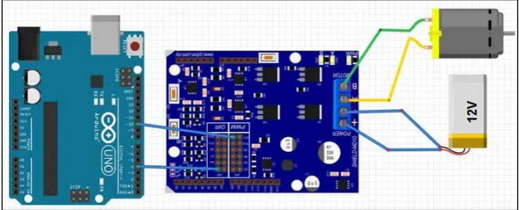
The components and hardware can be summarized according to a block diagram that is shown in Figure 3.2 while Figure 3.3 shows circuit diagram for a single motor developed by Fritzing software. Major components are two DC geared motors (SPG30E-30K) with encoder, the 10A NMOS H-Bridge motor driver, the Arduino Uno microcontroller, the DTMF module (MT8870), and a smartphone.
Smartphone (built-in sensors) DTMF Signal DTMF Decoder (MT8870) 4-bit DC Motor Left DC Motor Right NMOS H-Bridge Arduino Micro-controller PWM1 + PWM2
Figure 3.2: The block diagram of hardware development.
[image:26.595.113.525.291.499.2] [image:26.595.131.506.555.707.2]The DC geared motors were chosen as the driven mechanism in this project because of it is easy to control, clean, quiet and the most popular used in mobile
robot design. The characteristics are shown in Figure 3.4. From the figure, the maximum torque (stall torque) equal to 23.5m Nm at 1.8A (stall current), while for efficiency (50% of duty rate), the rated torque equal to 5.88m Nm at 0.41A (rated current).
Figure 3.4: SPG30E-30K Dc motor characteristics.
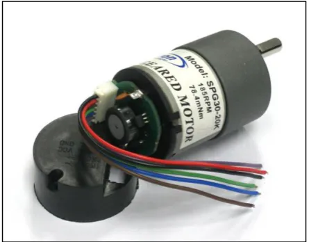
The reason using encoder in both DC motor is to put reference for distance analysis of translation movement. Besides, this encoder also can be used to balance the speed for two DC motor so that the movement of mobile robot always is stable in its route. Figure 3.5 depicts the SPG30E-30K that used to drive mobile robot in this project.
[image:27.595.152.488.195.397.2] [image:27.595.208.431.551.725.2]17
The model is formed by quadrature Hall Effect encoder board which is designed to fit on the rear shaft of the DC motor as shown in above figure. Two Hall Effect
[image:28.595.144.494.276.540.2]sensors are placed 90° apart to sense and produce two outputs signal named A and B which is; 90° out of phase and allowing the direction of rotation to be determined. For further understanding, Table 3.1 (a) and (b) is showing the state diagram while in Figure 3.6, it is showing the waveform signal that will be produced by the encoder; consequence from the rotational movement of the DC motor.
Table 3.1: State diagram for SPG30E-30K model; (a) Clockwise Rotation, (b) Counter Clockwise Rotation
a)
PHASE Signal A Signal B
1 0 0
2 0 1
3 1 1
4 1 0
b)
PHASE Signal A Signal B
1 1 0
2 1 1
3 0 1
4 0 0
Figure 3.6: The waveform signals.
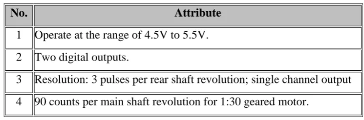
This encoder provides three counts per revolution of the rear shaft. To be simplified, Table 3.2 below specifies the quadrature Hall Effect encoder for SPG30E-30K:
Table 3.2: The quadrature Hall Effect encoder attributes.
No. Attribute
1 Operate at the range of 4.5V to 5.5V.
2 Two digital outputs.
3 Resolution: 3 pulses per rear shaft revolution; single channel output
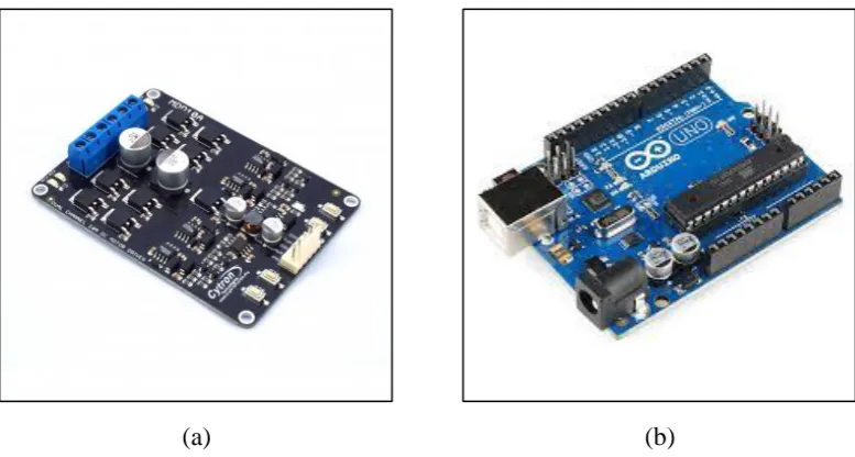
[image:28.595.131.504.638.761.2]For interfacing, the fully NMOS H-bridge dual channel 10A motor driver is needed to drive both DC motors for forward and backward movements. The motor
driver MDD10A model is depicted in Figure 3.7 (a). It is designed to drive two DC motor with high current up to 10A continuously without the heat sink since it has been integrated with fully NMOS H-bridge. For instance, Table 3.3 shows the characteristics of MDD10A:
Table 3.3:The MDD10A motor driver characteristics.
No. Characteristic
1 Bi-directional control for two brushed DC motor.
2 Voltage ranges from 5V to 25V.
3 Maximum current up to 10A continuous and 30A peak (10s) for each channel.
4 Speed control PWM frequency up to 25 KHz.
Smartphone will be attached on the robot chassis to utilize the built-in sensors and connected to the DTMF decoder module, MT8870. The Arduino microcontroller will be ruled to translate 4-bit data from DTMF module to control the PWM for DC motors via H-Bridge motor driver.
(a) (b)
Figure 3.7: (a) MDD10A dual channel motor driver; (b) Arduino Uno.
[image:29.595.110.530.235.356.2] [image:29.595.124.513.453.661.2]19
architecture development, so it is necessary to use low cost microcontroller rather than using microcontroller with high specifications. It is operates in between 3.3V till
5V from external supplied voltages like battery. For novice in the programming world, Arduino provides a Java based platform called Integrated Development Environment (IDE) and the codes written in C or C++. All programs to control DC motor written in this platform.
[image:30.595.138.525.191.437.2](a) (b)
Figure 3.8: (a) Arduino board schematic diagram; (b) PWM concept.
Figure 3.8 (a) depicts the schematic for input and output (IO) pins for Arduino Uno Rev3. It has six analogue input pins (A0-A5) that can be used to assign voltage value needed for the electronic devices output such as DC motor. While for digital pins (D0-D13), it can be used as IO depends on assigned function from user.
In this project, both DC motors will be controlled by using pulse width modulation (PWM) technique that programmed by Arduino. The concept of PWM is based on Figure 3.8 (b). PWM is a technique for getting analogue results with digital means [21]. Digital control will be used to form a square wave (a signal switched between on and off). This on-off pattern can simulate voltages in between full on (5V) and off (0V) by changing the portion of the time the signal spends on versus the time that the signal spends off. The pulse width term came from the duration of “on time signal” in the square wave. A code “analogWrite ( )” is on a scale of 0-255 bits
DTMF decoder module, type MT8870 is used for decoding the mobile DTMF tone signal received from the smartphone into 4-bit digital signal is shown in
Figure 3.9 (a) and (b) below. Based on Figure 3.9 (b), the decoder is operated with a 3.58 MHz crystal along with capacitor (C1) used to filter the noise and two unit resistors (R1 and R2) is used to amplify the input signal.
In this project, the module is connected to smartphone through audio jack. Table 3.4 shown DTMF signals in 4-bit data that will be used according to buttons 0 to 9 including button # (hash) and * (star). Each dial signal is decoded into 4-bit data and will be sent to Arduino microcontroller to control DC motors (movements of mobile robot).
(a)
(b)
21
Table 3.4: DTMF signal decode.
Dial Command Q4 Q3 Q2 Q1
1 Turn slightly left forward 0 0 0 1
2 Forward 0 0 1 0
3 Turn slightly right forward 0 0 1 1
4 Turn left 0 1 0 0
5 Stop 0 1 0 1
6 Turn right 0 1 1 0
7 Turn slightly left reverse 0 1 1 1
8 Reverse 1 0 0 0
9 Turn slightly right reverse 1 0 0 1
The last major component to design and construct mobile robot in this project is smartphone. A smartphone that used is Samsung Galaxy Note II model because of availability. This model is chosen based on its processing performance which it was integrated with Quad-Core processor with 1.6 GHz CPU speed. This powerful processor can provide more efficiency for complex algorithm calculation especially to create localisation strategies. Table 3.5 is showing specs comparison between Note II and other smartphones that has been mentioned in literature review. From the table, Note II has more type of sensors, biggest internal memory, and longest battery lifetime compared to other smartphones.
[image:32.595.180.459.89.321.2]i. Accelerometer:
(a)
(b)
Figure 3.10: (a) Mass on spring concept; (b) mass under gravity
This feature usually used to measure acceleration as well as tilt, tilt
angle, incline, rotation, vibration and collision. It is easiest to visualize as a mass on a spring as show in Figure 3.10 (a). In Figure 3.10 (b) the mass will droop under gravity because the force of gravity on the mass acts and pulls it down. The accelerometer measures 1g because that is the amount of earth’s gravity. For explanation, there is additional force holding the
[image:33.595.261.412.85.435.2]23
Figure 3.11: Linear movement of accelerometer.
In mobile phone application, an accelerometer can automatically modify the device's screen orientation vertically or horizontally. Advantage of the accelerometer sensor includes a high accuracy even in applications with noises. Example, with Kalman filtering algorithm, accelerometer can do more accurate in positioning when it is combined with encoders.
ii. Gyroscope:
Figure 3.12: A visual of gyroscope.
A gyroscope is a device that senses an angular velocity. This applied by the Coriolis Effect theorem [22]. Based on Figure 3.12, the Coriolis Effect happens when there is a mass that’s moving and the frame
[image:34.595.272.420.68.221.2] [image:34.595.215.472.435.624.2]rotating. For the analogy, the Earth is rotating, so the Earth’s rotation has
some impact on things for example, weather systems effect.
Generally gyroscope is used in robotic applications for balancing, sending corrections to motors, as well as for drones to stabilize the flight. In smartphones, this sensor also can monitor and control device orientation, positions, direction, angular motion and rotation. Gyroscope in smartphones helps to determine the position and orientation of the phone.
iii. Magnetometer (Compass):
(a)
(b)
Figure 3.13: (a) A conventional compass; (b) Compass sensor.
[image:35.595.259.433.296.608.2]56
6 REFERENCES
[1] R. V Aroca, A. P. B. S. De Oliveira, and L. M. G. Gonçalves, “TOWARDS SMARTER ROBOTS WITH SMARTPHONES,” pp. 1–6.
[2] S. P. Electronics, “S.” [Online]. Available: http://skpang.co.uk/catalog/inputoutputrelay-daughter-board-p-223.html. [Accessed: 27-May-2014].
[3] C. C. Soon, “Smart-phone Operated Robot,” pp. 1–7.
[4] G. N. Coelho, “Autonomous Mobile Robot Navigation using Smartphones Extended Abstract,” 2008.
[5] W.-W. Kao and B. Q. Huy, “Indoor navigation with smartphone-based visual SLAM and Bluetooth-connected wheel-robot,” 2013 CACS Int. Autom. Control Conf., vol. 1, pp. 395–400, Dec. 2013.
[6] M. Thesis and C. Science, “A N A NALYSIS OF THE B LUETOOTH,” no. June, 2009.
[7] T. S. Vamsi and K. Radha, “ARM Based Stair Climbing Robot Controlling Through DTMF Technology,” no. 3, pp. 71–74, 2013.
[8] S. Tang, “Performance analysis of an integrated wireless network using WiMAX as backhaul support for WiFi traffic,” 2011 - MILCOM 2011 Mil. Commun. Conf., pp. 1833–1837, Nov. 2011.
[9] A. Ibrahim and D. Ibrahim, “Real-time GPS based outdoor WiFi localization system with map display,” Adv. Eng. Softw., vol. 41, no. 9, pp. 1080–1086, Sep. 2010.
[10] “Ehab Aboudaya, Lappeenranta Univ. Of Technol. Finland, ‘Mobile Teleoperation of a Mobile Robot’, Thesis for the Degree of Master of Science in Technology, 2010.”
[12] V. Nakka and A. Kabirdas, “Design and Realization of Augmented Reality Based Navigation Assistance System,” vol. 2, no. 6, pp. 2842–2846, 2011.
[13] “J. J. Leonard and H. F. Durrant-Whyte. Mobile robot localization by tracking geometric beacons. IEEE Transactions on Robotics and Automation, 7(3):376–382, 1991.” .
[14] G. N. Coelho, “Autonomous Mobile Robot Navigation using Smartphones e Guilherme Nogueira Coelho dos Santos Dissertation for the achievement of the degree Master in Information Systems and Computer Engineering,” no. November, 2008.
[15] M. J. Matari´ c, The Robotics Primer, 1st editio. The MIT Press, 2007.
[16] M. Carreras, P. Ridao, R. Garcia, and T. Nicosevici, “Vision-based localization of an underwater robot in a structured environment,” 2003 IEEE Int. Conf. Robot. Autom. (Cat. No.03CH37422), vol. 1, pp. 971–976, 2003.
[17] J. Bruce, T. Balch, and M. Veloso, “Fast and inexpensive color image segmentation for interactive robots,” Proceedings. 2000 IEEE/RSJ Int. Conf. Intell. Robot. Syst. (IROS 2000) (Cat. No.00CH37113), vol. 3, pp. 2061–2066, 2000.
[18] K. Yoon and I. Kweon, “Artificial landmark tracking based on the color histogram,” Proc. 2001 IEEE/RSJ Int. Conf. Intell. Robot. Syst. Expand. Soc. Role Robot. Next Millenn. (Cat. No.01CH37180), vol. 4, pp. 1918–1923, 2001.
[19] G. Huang and H. Lin, “Applications of Highly Accurate Localization and Navigation to Mobile Robot,” no. October, pp. 4758–4763, 2009.
[20] T. Bräunl, Embedded Robotics: Mobile Robot Design and Applications with Embedded Systems, 2nd Editio. Germany: Springer Berlin Heidelberg, 2006.
[21] “PWM.” [Online]. Available: http://arduino.cc/en/Tutorial/PWM. [Accessed: 19-Jun-2014].
![Figure 2.2: The P3DX robot overall system [10]. ](https://thumb-us.123doks.com/thumbv2/123dok_us/8764966.895920/17.595.220.419.68.215/figure-p-dx-robot-overall.webp)
![Figure 2.4: General block diagram [7]. ](https://thumb-us.123doks.com/thumbv2/123dok_us/8764966.895920/18.595.191.450.571.756/figure-general-block-diagram.webp)
![Figure 2.6: The coded pattern that inspired the localization algorithm [16].](https://thumb-us.123doks.com/thumbv2/123dok_us/8764966.895920/20.595.187.451.651.720/figure-coded-pattern-inspired-localization-algorithm.webp)
![Figure 2.8: (a) Model of robot motion; (b) Model of location measurement [19]. ](https://thumb-us.123doks.com/thumbv2/123dok_us/8764966.895920/21.595.102.538.396.614/figure-model-robot-motion-b-model-location-measurement.webp)