DC-DC BOOST CONVERTER BY H-INFINITY CONTROLLER
ABDOLKAREM SALEM EBSHISH
A thesis report submitted in partial
fulfillment of the requirement for the award of the Degree of Master of Electrical and Electronic Engineering
Faculty of Electrical and Electronic Engineering Universiti Tun Hussien Onn Malaysia
ABSTRACT
DC-DC converters are electronic devices used to change DC electrical power efficiently from one voltage level to another. Operation of the switching devices causes the inherently nonlinear characteristic of the DC-DC converters including one known as the Boost converter.
Consequently, this converter requires a controller with a high degree of dynamic response. Proportional-Integral- Differential (PID) controllers have been usually applied to the converters because of their simplicity. However, the main drawback of PID controller is unable to adapt and approach the best performance when applied to nonlinear system. It will suffer from dynamic response, produces overshoot, longer rise time and settling time which in turn will influence the output voltage regulation of the Boost converter.
CONTENTS
TITLE i
DECLARATION ii
DEDICATION iii
ACKNOWLEDGEMENT iv
ABSTRACT v
TABLE OF CONTENTS vi
LIST OF TABLES xi
LIST OF FIGURES x
LIST OF SYMBOLES AND ABBREVIATIONS xii
CHAPTER 1 INTRODUCTION 1
1.1 Introduction 1
1.2 Problem statement 3
1.3 Project objective 4
1.4 Project scope 4
1.5 Project report layout 5
CHAPTER 2 LITERATUREREVIEW 6
2.1 Introduction 6
2.2 DC to DC Converter 7
2.3 Boost Converter 10
2.3.1 Duty Cycle 11
2.3.2 Voltage and Current Relationships 11
2.3.3 The Output Voltage Ripple 12
2.5 Control systems 13
2.5.1 PID Controller 14
2.5.1.1 Typical steps for designing a PID
controller 15
2.5.1.2 Using of PID Control 15
2.5.1.3 Advantages of PID Control 16
2.5.2 Fuzzy logic controller system 16
2.5.2.1 Using of fuzzy logic control 17 2.5.2.2 Advantages fuzzy logic control 17
2.6 H∞ controller 18
2.6.1 Formulation of the H∞ Problem 19
2.6.1.1 Uncertainty the H∞ Problem 19
2.6.1.2 Sensitivity Reduction 20
2.6.1.3 Mixed Performance and Robustness
Objective 21
2.6.2 Design of H∞ controller 22
2.6.3 Using of H∞ Control 23
2.6.4 Advantages of H∞ Control 23
CHAPTER 3 METHODOLOGY 24
3.1 Introduction 24
3.2 Boost Converter Parameter 26
3.3 H∞ controller and Its Operational Methodology 27 3.3.1 State-Space Equation and Calculation for
Boost Converter 28
3.3.2 Transfer function for boost converter 33
3.3.3 Function of K
∞
controller 33CHAPTER 4 RESULT AND ANALYSIS 34
4.1 Introduction 34
4.3 Analysis for Boost Converter 38 4.3.1 Analysis for Open Loop Boost Converter 38 4.3.2 Analysis for Boost Converter with PID Controller 39 4.3.3 Analysis for Boost Converter with H∞ Controller 45 4.4 summaries of H∞ Controller and PID Controller 51
CHAPTER 5 CONCLUSION AND RECOMMENDATION 52
5.1 Conclusion 52
5.2 Recommendation 53
REFERENCE 54
LIST OF TABLES
3.1 The value of all parameters can be determined as below
parameters and values for boost converter 27
LIST OF FIGURES
2.1 Boost Converter 8
2.2 Buck Converter 9
2.3 Buck-Boost Converter 9
2.4 Cuk Converter 10
2.5 The Duty Cycle For Switching Period During Steady State 11
2.6 An Open-Loop Control System 13
2.7 Close-Loop Control System 14
2.8 Proportional-Integral-Derivative (PID) Controllers 14
2.9 Fuzzy Logic Controller Schematic 16
2.10 Fuzzy Logic Controller (FLC) Overall Structure 17 2.11 Standard Presentation of Model with Uncertainty 19 2.12 Standard Presentation of Model without Plant perturbation 20 2.13 Standard H∞ Control Problem for DC-DC Converter 22 3.1 Shows the Overview of the Methodology Flow Chart
of This Project 25
3.2 Block Diagram For Propose DC-DC Boost Converter 26 3.3 Standard H∞ Control Problem for DC-DC Converter 28
3.4 Boost Converter Circuit Topology 29
3.5 Boost Converter Equivalent Circuit when Switch is ‘ON’ 29 3.6 Boost Converter Equivalent Circuit when Switch is ‘OFF’ 30 4.1 Simulation Open Loop Boost Converter by Using
MATLAB Software 35
4.3 Simulation Boost Converter with H∞ Controller 37 4.4 (a)Results on Output Voltage and Output Current for
Open Loop Circuit Boost Converter 38
4.4 (b) Results on Ripple Voltage, Setting Time and Over Peak
for Output Voltage Open Loop Circuit Boost Converter 39 4.5 (a) Results on Output Voltage and Output Current Boost
Converter with PID Control (Output Voltage=13V) 40 4.5 (b) Results on Ripple Output Voltage, Setting Time and
Over Peak Voltage Boost Converter with PID Controller 41 4.6 (a) Results on Output Voltage and Output Current Boost
Converter with PID Control (Output Voltage=15V) 40 4.6 (b) Results on Ripple Output Voltage, Setting Time and
Over Peak Voltage Boost Converter with PID Controller 41 4.7 (a) Results on Output Voltage and Output Current Boost
Converter with PID Control (Output Voltage=18V) 40 4.7 (b) Results on Ripple Output Voltage, Setting Time and
Over Peak Voltage Boost Converter with PID Controller 41 4.8 (a) Results on Output Voltage and Output Current Boost
Converter with H∞ Control (Output Voltage =13V) 40 4.8 (b) Results on Ripple Output Voltage, Setting Time and
Over Peak Voltage Boost Converter with H∞ Controller 41 4.9 (a) Results on Output Voltage and Output Current Boost
Converter with H∞ Control (Output Voltage =15V) 40 4.9 (b) Results on Ripple Output Voltage, Setting Time and
Over Peak Voltage Boost Converter with H∞ Controller 41 4.10 (a) Results on Output Voltage and Output Current Boost
Converter with H∞ Control (Output Voltage =18V) 40 4.10 (b) Results on Ripple Output Voltage, Setting Time and
LIST OF SYMBOLS AND ABBREVIATIONS
C - Capacitor
- The critical values capacitor CCM - Continuous Conduction Mode
D - Duty Cycle
DC - Direct Current
DCM - Discontinuous Conduction Mode
E - Error
-
FrequencyFLC - Fuzzy Logic Controller
Fs - Frequency Switching
H∞ - H-infinity Controller
KD - Derivative Gain
KI - Integral Gain
KP - Proportional Gain
KCL - Kirchhoff Current Law KVL - Kirchhoff Voltage Law
L - Inductor
MIMO - Multi-Input Multi-Output
MOSFET - Metal-Oxise- Semiconductor Field- Effect Transistor
PID - Proportional Integral Derivative PWM - Pulse Width Modulation
S - Switch
T - Time
V
C - Voltage (Calculation)
- Voltage Inductor V
o - Output Voltage
V
s - Input Voltage
V
ref - Reference Output
- Voltage Ripple
W - Weight Function
CHAPTER I
INTRODUCTION
1.1 Introduction
DC-DC converters are widely used in switched-mode power supplies, adjustable speed drives, uninterruptible power supplies and many other applications to change the level of an input voltage to fulfill required operating conditions [1].
DC-DC converters are circuits which convert sources of DC from one voltage level to another by changing the duty cycle of the main switches in the circuits. Since DC-DC converters are nonlinear systems, they represent a big challenge for control design. Since classical control methods are designed at one nominal operating point, they are not able to respond satisfactorily to operating point variations and load disturbance. They often fail to perform satisfactorily under large parameter or load variations [2].
The DC-DC converters can have two distinct modes of operation: Continuous conduction mode (CCM) and discontinuous conduction mode (DCM). In practice, a converter may operate in both modes, which have significantly different characteristics. However, for this project only considers the DC-DC converters operated in CCM. CCM is for efficient power conversion and DCM for low power or stand-by operation [14]. The DC-DC converter is considered as the heart of the power supply, thus it will affect the overall performance of the power supply system. The converter accepts DC and produces acontrolled DC output.
Operation of the switching devices causes the inherently nonlinear characteristic of the DC-DC converters. Due to this unwanted nonlinear characteristics, the converters requires a controller with a high degree of dynamic response. Pulse Width Modulation (PWM) is the most frequently consider method among the various switching control method [12]. In DC-DC voltage regulators, it is important to supply a constant output voltage, regardless of disturbances on the input voltage.
There are many control techniques used for control in DC-DC converter, for example: PID Controller, Fuzzy logic controller and H-infinity Controller (H∞).
i) PID Controller: PID stands for proportional, integral, derivative are one of the most popular feedback controller widely use in processing industry. It is easy to understand the algorithm to produce excellent control performance [18].
ii) Fuzzy logic controller: Fuzzy control is a practical alternative for a variety of challenging control applications since it provides a convenient method for constructing nonlinear controllers via the use of heuristic information [19].
iii) H-infinity Controller (H∞): Throughout the decades of 1980 and 1990, H∞ control method had a significant impact in the development of control systems; nowadays the technique has become fully grown and it is applied on industrial problems. The H∞ methods are used in control theory to synthesize controllers achieving robust performance or stabilization. The H∞ optimal control theory is an elective method to design a controller to guarantee the performance with the worst-case disturbance [20].
1.2 Problem statement
1.3 Project objective
The objectives of this project are:
i) To model and analyze of the DC-DC Boost converter without controller (open loop).
ii) To design a H∞ controller to control the switching of DC-DC Boost converter. iii) To analyze the voltage output for DC-DC Boost converter between closed loop.
1.4 Project scope
a) Modeling DC to DC converter:
i) Study the system (plant) to be controlled and obtain initial information about the control objectives.
ii) Model the system and simplify the model, if necessary.
iii) Scale the variables and analyze the resulting model; determine its properties. b) Modeling H∞ controller.
i) Design a controller.
This thesis is organized as follows;
i) Chapter 1 briefs the overall background of the study. A quick glimpse of study touched in first sub-topic. The heart of study such as problem statement, project objective, project scope and project report layout is present well through this chapter.
ii) Chapter 2 covers the literature review of previous case study of types of DC-DC converters. General information about Boost Converter and theoretical revision on H∞ control system also described in this chapter.
iii) Chapter 3 presents the methodology used to design open loop Boost Converter and closed loop for PID controller and closed loop for H∞ controller. All the components that have been used in designing of H∞ controller are described well in this chapter.
iv) Chapter 4 reports and discuss on the results obtained based on the problem statements as mentioned in the first chapter. The simulation results from open loop, PID controller and the proposed of H∞ controller will be analyzed and comparison with helps from set of figures and tables.
CHAPTER II
LITERATURE REVIEW
2.1 Introduction
There are many previous researches focusing in DC-DC converters such as Boost Converter. And, to get maximum performance and stability of designed system, different type of controller have been used. A thorough literature overview was done on the usage of different types of controllers.
Formulation of a PID controller is introduced to replace the output voltage derivative with information about the capacitor current, thus reducing noise injection. This formulation preserves the fundamental principle of a PID controller and incorporates a load current feed-forward as well as inductor current dynamics [4].
Design and implementation issue, and experimental results for the linear PID and PI controller and fuzzy controller were compared. The design of linear PID and PI controllers and fuzzy controllers requires quite different procedures. Design of the fuzzy controller does not require a mathematical model, while a small signal model is necessary for the design of PID controllers using frequency response method [5].
than conventional sliding mode controller [10].
The idea of the H∞ controller is based on the fact that the designer is making effort to find the “best” controller among others which minimizes the H∞ norm of some kind of transfer function responsible for the proper performance of the closed-loop system [11].
2.2 DC to DC Converter
DC-DC is an electronic circuit which converts a source of direct current (DC) from one voltage level to another. In other word, converting the unregulated DC input to controlled DC output with a desired voltage level [12].
DC-DC converters are widely used in today’s industrial or commercial electronic devices to manipulate a dc voltage source. As the name implies, DC-DC converters work exclusively to take a dc voltage input and convert it to output a different level of dc voltage. They can either step-up or step-down the input dc voltage while maintaining minimal power loss during the process. There are many different topologies available for use such as Buck (step down), Boost (Step up), Flyback, Push-Pull, etc.
“cushion” in the case of unstable or changing input level and/or load. Secondly, these converters are able to split a single constant source to several different voltage levels by using a multi-winding transformer. Other benefits of using DC-DC converters include the ability to operate the system in high switching frequency operation. This would further result in a relatively small system crucial especially in portable and vehicle applications [13].
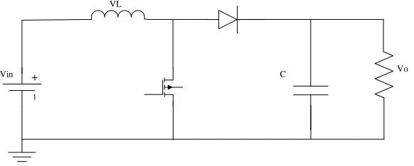
There are four main types of converter usually called the boost, buck, buck -boost and cuk converters [1]. A -boost converter (step-up converter), shows in Figure 2.1 as its name suggests steps up the input DC voltage value and provides at output. This converter contains basically a diode, a transistor as switches and at least one energy storage element. Capacitors are generally added to output so as to perform the function of removing output voltage ripple and sometimes inductors are also combined with.
VL
[image:18.612.185.476.352.469.2]Vin C Vo
Figure 2.1: Boost Converter
Its operation is mainly of two distinct states:
i) During the ON period, switch is made to close its contacts which results in increase of inductor current.
ii) During the OFF period, switch is made to open and thus the only path for inductor current to flow is through the fly-back diode ‘D’ and the parallel combination of capacitor and load. This enables capacitor to transfer energy gained by it during ON period.
accumulate energy in inductor and then discharging the inductor’s energy to the load.
VL
[image:19.612.194.466.139.264.2]Vin C Vo
Figure 2.2: Buck Converter
When the switch pictured above is closed (i.e. On-state), the voltage across the inductor is = − The current flowing through inductor linearly rises. The diode doesn’t allow current to flow through it, since it is reverse-biased by voltage V.
For Off Case (i.e. when switch pictured above is opened), diode is forward biased and voltage is = − (neglecting drop across diode) across inductor. The inductor current which was rising in ON case now decreases
.
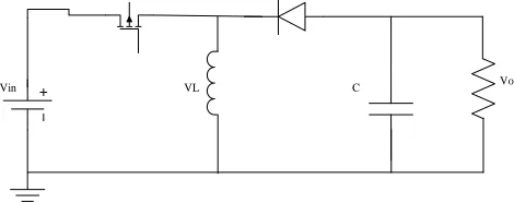
The buck–boost converter, this type of converter gives output voltage which is having greater or lesser magnitude than input value of voltage. Based on duty ratio of switching transistor, output voltage is adjusted.
When switch is turned ON, then the inductor is connected to input voltage source. This leads to accumulation of energy in the inductor and capacitor performs the action of supplying energy to load. When switch is turned OFF, the inductor is made to come in contact with capacitor and load, so as to provide energy to load and discharged capacitor [3].
VL
Vin C Vo
[image:19.612.211.446.591.684.2]The Cuk converter, this type of converter that has an output voltage magnitude that is either greater than or less than the input voltage magnitude. The control of this type DC-DC converters are more difficult than the buck type where the output voltage is smaller than the source voltage. The difficulties in the control of boost converters are due to the non-minimum phase structure since, the control input appears both in voltage and current equations [2].
VL1
Vin C2
VL2 C1
Figure 2.4: Cuk Converter
2.3 Boost Converter
A boost converter (step-up converter), steps up the input DC voltage value and provides at output. It consists of an inductor L, capacitor C, controllable semiconductor switch S, diode D, and Load resistance R as depicted by Figure 2.1. Capacitors are generally added to output so as to perform the function of removing output voltage ripple. The boost converter is one of the most important nonisolated step-up converters.
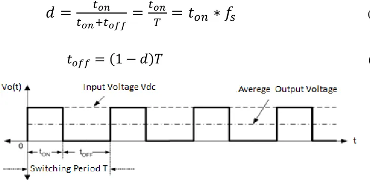
Define duty cycle (d) which depends on ton and switching frequency fs
(2.1) [image:21.612.151.516.175.359.2]
(2.2)
Figure 2.5: The Duty Cycle for Switching Period during Steady State
2.3.2 Voltage and Current Relationships
The analysis proceeds by examining the conductor voltage and current for the switch closed and again for the switch open. Find that at steady-state operation
(2.3)
The minimum combination of inductor and switching frequency for continuous current in the boost converter is therefore
The critical values capacitor
(2.5)
2.3.3 The Output Voltage Ripple
The preceding equations were developed on the assumption that the output voltage was a constant, implying an infinite capacitance. In practice, a finite capacitance will result in some fluctuation in output voltage, or ripple
(2.6)
2.4 State Space Averaged Model of Boost Converter
Using state-space important to find k controller, the process of state-space averaging is best explained by first writing the linear differential equations of the power stage for the ON and OFF states and by formulating the general matrix equations.
(2.7)
(2.8) The process of state-space averaging is best explained by first writing the linear differential equations of the power stage for the ON and OFF states, and by formulating the general matrix equations [3,15,16].
There are four primary reasons of control design namely power amplification, remote control, convenience of input form and compensation for disturbances:
i) Power amplification is needed as sometimes a control system needs to produce certain level of power or normally called power gain, in order to activate a system such as rotate an antennas which requires large amount of power.
ii) Remote control basically used in a robot control technology. It compensates human disabilities such as using a remote control robot for underwater/deep sea scientific research.
iii) Control systems can also be used to provide convenience by changing the form of the input For example, in forklift operation, the input is a weight detector and the output is a torque (motor) [17].
iv) Control systems have a capability to compensate for disturbances. That mean, even there are disturbance of input signal, a process or a system still able to produce a correct output. In a process of positioning an antenna for example, if antenna position changes because of a wind forces, the system should be able to detect the disturbance and correct the antenna’s position.
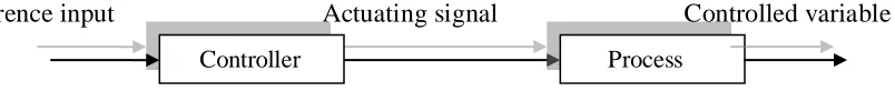
The objectives of a control system can be achieved by employing two possible control strategies. These control strategies are open-loop control system (feed forward control system) and close-loop control system (feedback control system). Figure 2.6 and Figure- 2.7 shows open-loop control system and close-loop control system respectively [17].
[image:23.612.138.540.618.659.2]Reference input Actuating signal Controlled variable
Figure 2.6: An Open-Loop Control system.
Desired output Output
Figure 2.7: Close-Loop Control System.
2.5.1 PID Controller
PID stands for proportional, integral, derivative are one of the most popular feedback controller widely use in processing industry. It is easy to understand the algorithm to produce excellent control performance.
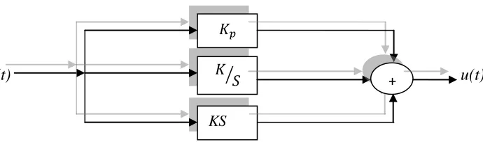
The PID consists of three basic modes that are proportional modes, integral modes and derivative modes. Generally three basis algorithm uses are P, PI and PID. This controller has a transfer function for each modes, proportional modes adjust the output signal in direct proportional to the controller output. A proportional controller ( ) reduced the error but not eliminated it. An integral controller ( ) will have the effect of eliminating the steady-state error but it may worsen the transient respond. The derivative controller ( ) will have the effect of increasing the stability of the system, reducing the overshoot and improving the transient respond [20].
e(t) u(t)
Figure 2.8: Proportional-Integral-Derivative (PID) Controllers controller
Measurement
Comparator Process
KS
[image:24.612.185.530.573.675.2]desired output response. It is not necessary to implement all three controllers if not needed, if P or PI controller gives a good enough response, there is no need to implement the derivative controller.
Controllers respond to the error between a selected set point and the offset or error signal that is the difference between the measurement value and the set point. Optimum values can be computed based upon the natural frequency of a system. Higher gain makes the output change larger corresponding to the error. Integral can be added to the proportional action to ramp the output at a particular rate thus bring the error back toward zero. Derivative can be added as a momentary spike of corrective action that tails off. Derivative can be a bad thing with a noisy signal [18].
2.5.1.1 Typical steps for designing a PID controller
At first determine what characteristics of the system need to be improved, after that use to decrease the rise time, use to reduce the overshoot and settling time and use to eliminate the steady-state error.
2.5.1.2 Using of PID Control
sophisticated control strategies, such as model predictive control, are also organized hierarchically.
2.5.1.3 Advantages of PID Control
The proposed formulation preserves the basic principle of a PID controller and formulation of a conventional PID controller is introduced to replace the output voltage derivative with information about the capacitor current, thus reducing noise injection [4].
2.5.2 Fuzzy logic controller system
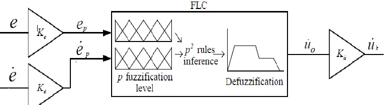
Since its introduction in 1965 by Lotfi Zadeh (1965) [7], the fuzzy set theory has been widely used in solving problems in various fields, and recently in educational evaluation. Fuzzy control is a practical alternative for a variety of challenging control applications since it provides a convenient method for constructing nonlinear controllers via the use of heuristic information. Figure 2.9 shows the structure of the fuzzy logic controller [19]. During the preprocessing, already some calculations are performed which have no real connection to the fuzzy control process, but nevertheless can yield a lot of influence.
[image:26.612.142.520.520.693.2]and defuzzification. General structure of FLC is shown in Figure 2.10.
Figure 2.10: FLC Overall Structure.
2.5.2.1 Using of fuzzy logic control
2.5.2.2 Advantages fuzzy logic control
Fuzzy controller is able to achieve faster transient response, less overshoot, better rejection to disturbances and less dependence on the operating point and increasing efficiency and reducing error, voltage and current ripples [5] [10].
2.6 H∞ controller
Throughout the decades of 1980 and 1990, H∞ control method had a significant impact in the development of control systems; nowadays the technique has become fully grown and it is applied on industrial problems.
2.6.1.1 Uncertainty the H∞ Problem
Consider the plant model with feedback as shown in Figure 2.11. In this case Δ(s) represents plant parameter uncertainty, P(s) represents the plant nominal transfer function and K(s) represents feedback control [21].
Error z
External Inputs (w) External Output u y
[image:29.612.150.526.254.429.2]
Control Signals Measured Variables Figure 2.11: Standard Presentation of Model with Uncertainty
Where w represents an external disturbance, y is the measurement available to the controller, u is the output from the controller, and z is an error signal that it is desired to keep small. The transfer function G represents not only the conventional plant to be con-trolled, but also any weighting function included to specify the desired performance [20].
(S)
9 P (S)
2.6.1.2 Sensitivity Reduction
[image:30.612.146.494.201.321.2]
The first mission of the design is to make the system insensitive to external disturbances. This is equivalent to make z as independent of w as possible. If the plant perturbation Δ(s) is ignored, then the Model simplifies to that shown in Figure 2.12 [21].
Figure 2.12: Standard Presentation of Model without Plant Perturbation Δ(s). From the figure
(2.9)
Suppose P(s) can be partitioned as follows
P
(
s
) =
(2.10)
From equation (2.9) and (2.10)
z= w + u (2.11) y = w + u (2.12)
then with the feedback law u = K(s)y can eliminate u and y
z =[ + K (I − K w
The following set of characteristics is possible:
• To achieve good disturbance rejection from external signals in the low-frequency region. This can be achieved by making the sensitivity S = (I + PK small as ω → 0. • Make the closed loop transfer function small at high frequencies limit excitation by noise. This can be achieved by making T = I − S = I − (I + PK small as ω → ∞.
• Guard against instability from parameter variations. This is achieved by minimizing K(I + PK . Then formulate the H∞ problem as the minimization of the function
(
P
,
K
)=
(2.14)
2.6.2 Design of H∞ controller
[image:32.612.146.511.205.409.2]From the Standard Presentation of Model in Figure 2.12, translate the problem of designing a controller for DC-DC Converter to the standard problem of control, as illustrated in Figure 2.13 [9].
Figure 2.13: Standard H∞ Control Problem for DC-DC Converter.
When G is the DC-DC Converter, K is the controller to be designed and W is a stable weight function. the vector reference voltage and represents output voltage. The standard problem of H∞ control is to find a controller K∞ that stabilizes the plant P minimizing the infinity norm of the close-loop transfer function [8].
Can find the DC-DC converter G by used state-space equation
control input, z is weighted output and y is measurement output. A, B1, B2, C1, C2, D11, D12, D21, D22 are real matrixes with appropriate dimensions. Than by The DC-DC converter G and weight function W can be combined to form the plant P.
2.6.3 Using of H∞ Control
The H∞ methods are used in control theory to synthesize controllers achieving robust performance or stabilization. some of application H∞ control an aircraft autopilot design, Vertical plane dynamics of an aircraft, Large space structure, Attitude control of a flexible space platform and Gas turbine control [22].
2.6.4 Advantages of H∞ Control
CHAPTER III
METHODOLOGY
3.1 Introduction
This chapter will cover the details explanation of methodology that is being use to make this project complete and working well. Matlab/simulink software is used to achieve the objectives of the project that will complete. With the aim to evaluate this project, the methodology based on system development and optimization output voltage of boost converter by using H∞ controller for closed loop compared with PID control. The Flow chart is Figure 3.1 shows the flows and methods that will use for finding and analyzing data regarding the project related.
REFERENCE
1. Rubaai, Ahmed, and Mohamed F. Chouikha. "Design and analysis of fuzzy controllers for DC-DC converters." Control, Communications and Signal Processing, 2004. First International Symposium on. IEEE, 2004.
2. Dhali, Sumita, et al. "PWM-Based sliding mode controller for DC-DC boost converter." IJERA) International Journal of Engineering Research and Applications 2.1 (2012): 618-623.
3. Ghosh, Antip, and Mayank Kandpal. State-space average Modeling of DC-DC Converters with parasitic in Discontinuous Conduction Mode (DC-DCM). Diss. 2010.
4. Kapat, S. (2011). Formulation of PID Control for DC-DC Converters Based on Capacitor Current: A Geometric Context. IEEE, pp. 1-21.
5. Liping Guo et al. (2005). Comparative Evaluation of Linear PID and Fuzzy Control for a Boost Converter. IEEE, pp.555-560.
6. Haddad, A. H. "Editorial: Why H-infinity?." Automatic Control, IEEE Transactions on 32.10 (1987): 850-850.
7. H. I. A.li, Member IAENG, S. B. Mohd Noor, M. H. Marhaban, S. M. Bashi “Design of H-inf Controller with Tuning of Weights Using Particle Swarm Optimization Method”
8. Libau, Charles Muling. Transient response analysis for DC-DC boost converter. Diss. Universiti Tun Hussein Onn Malaysia, 2012
10. Shamim-Ul-Alam, Md, Muhammad Quamruzzaman, and K. M. Rahman. "Fuzzy logic based sliding mode controlled dc-dc boost converter." Electrical and Computer Engineering (ICECE), 2010 International Conference on. IEEE, 2010.
11. Ioannidis, G. C., and S. N. Manias. "Robust current assisted H∞ controller for boost converter in the presence of uncertainty and evaluation using μ-analysis." Power Electronics Specialists Conference, 2008. PESC 2008. IEEE. IEEE, 2008.
12. Jamali, Siti Hasmah. Voltage tracking of DC-DC boost converter using Gaussian Fuzzy Logic Controller. Diss. Universiti Tun Hussein Onn Malaysia, 2012
13. Gunawan, Tadeus. "Two-Phase Boost Converter." Master's Theses and Project Reports (2009): 200.
14. Elbaset, A., and Dr Hasaneen. "Design and simulation of DC/DC boost converter." Dr. Adel A. Elbaset (2008):
15. Dharmayanda, Hardian Reza, Agus Budiyono, and Taesam Kang. "State space identification and implementation of control design for small-scale helicopter." Aircraft Engineering and Aerospace Technology 82.6 (2010): 340-352.
16. Rezaei, Kamran. A Control Scheme for an AC-DC Single-Stage Buck-Boost PFC Converter with Improved Output Ripple Reduction. Diss. The University of Western Ontario, 2012.
17. Libau, Charles Muling. Transient response analysis for DC-DC boost converter. Diss. Universiti Tun Hussein Onn Malaysia, 2012.
18. Hartmut Bossel,PID Modeling and simulation, A. K. Peters, Ltd., Natick, MA, 1994.
19. P.Mattavelli, L.Rossetto, G.Spiazzi and P.Tenti, General-Purpose Fuzzy Controller for DC-Dc Converter, Proceedings of 1997, IEEE Transactions On Power Electronics, 1 January 1997, vol.12, no.1.
https://www.google.com/webhp?source=search_app#q=21.%09H%E2%88 %9E+Control.+J+Treurnicht.+May+15%2C+2007