© 2017, IRJET | Impact Factor value: 6.171 | ISO 9001:2008 Certified Journal
| Page 2037
Three Dimensional Non-Linear Seismic Analysis of a Cable Stayed
Bridge Using ANSYS
Muhammad Habib
1, 2,Lifei Yang
3, Nawaz Ali
4, Shuang Liu
5, Zhijun Chen
6, 71, 3, 5, 6
School of Civil Engineering and Mechanics, Huazhong University of Science and Technology, Wuhan, China
2, 4Civil Engineering Department, Balochistan University of Information Technology, Engineering and
Management Sciences, Quetta, Pakistan
Abstract -
The dynamic behavior of a cable stayed bridge is studied. The response of the cable stayed bridge is examined by carrying out non-linear static and dynamic (earthquake) analyses. Modes and the natural frequency of the bridge is studied by Modal analysis based on the Block Lanczos method. ANSYS is used to simulate the 3D model based on the Finite Element Method (FEM) .Cables are modeled by single element approach instead of multiple elements to reduce the data usage and computational time. The displacement convergence approach is used to avoid the convergence problems as cable stayed bridges are complex structures. The result shows that the bridge has complex modes due to the coupling effects for the free vibrations and it is more flexible in vertical direction than in transverse and longitudinal directions. Response of the bridge under earthquake loads is also studied. Transient analysis was performed for EI-Centro 1940 ground motion data of 10 second with a time interval of 0.0001 seconds. Important sections of girder and tower were carefully observed.Key Words: Dynamic Behaviour, Single-tower Cable Stayed Bridge, Modal Analysis, Time History Analysis, ANSYS
1. INTRODUCTION
Due to their efficient, economically viable, faster construction and aesthetically attractive looks have made cable stayed bridges as one of the most widely used bridge system for medium to long span bridges. At present these bridges have the ability to cover a span length from 200 m to 1200 m or even more. Of all the long span bridges being constructed nowadays, almost 90 percent are cable supported bridges [1].Recent development in the analysis and design of cable stayed bridges ensure to build this type of bridges with relatively small size of the sub structural elements. Rapid and efficient construction techniques also add to its popularity. With the advancement in design techniques, material properties and qualities and good construction techniques enable to achieve long spans with slender elements. To achieve slim, shallower and long span bridges, more advance and accurate techniques need to be developed in order to predict the structural response due to
the earthquake and wind loadings. During the last 70 years, since the collapse of the first Tocoma Narrows Bridge, dynamic study of the cable stayed bridges has become very important. A lot of research works both experimental and theoretical has been carried out to understand the behavior of the cable stayed bridges under the wind and earthquake loadings [2, 3].
Fleming and Egesli [4] proposed that the linear dynamic analyses were accurate enough to design a cable stayed bridge by studying a 2-D bridge model. Abdel Ghaffar and Nazmy [5] give motion equations for some 3-D hypothetical models by considering some of the nonlinear behaviors also. Abdul Ghaffar and khalifa [6] also consider the effect of vibration of the cables on the dynamic behavior of the cable stayed bridges. A lot of work related to earthquake effects is also done. Jamuna Bridge was studied for the earthquake effects on the basis of spectrum analysis and found that cable stayed bridges can withstand an earthquake acceleration up to 0.216g [7].
To save time and storage modal analysis is mostly performed. It is used to obtain information about the frequencies, mode shapes and modal participation factors. With increasing span, slim cross sections, low damping and high flexibility cable stayed bridges are more vulnerable to the earthquake and wind loadings. Major source of damping is greatly reduced in the cable stayed bridges as compared to conventional bridges. Cable stayed bridges have very low damping which is not even sufficient to overcome its own vibrations. To increase the damping of the system external damping devices are extensively used in nowadays cable supported bridges. But a lot of research is needed to be investigated the damping problems of the modern bridges and its economy [8]. Since 80’s a lot of work is being done focusing the seismic response of the cable stayed bridges [9-13]. Nonlinear behavior, supports condition role, cable vibrations and spatial variability were also studied. Some dynamic characteristics of interest of this study are frequencies, mode shapes, modal participation factor and effective modal masses. Vertical and transverse and torsional behavior is studied separately.
7
Professor, School of Civil Engineering and Mechanics, Huazhong University of Science and Technology,
Wuhan,
China
---***---© 2017, IRJET | Impact Factor value: 6.171 | ISO 9001:2008 Certified Journal
| Page 2038
In this study, a brief investigation is conducted on the dynamic response of the cable stayed bridges. Some of the basic concepts are discussed and these concepts will be used to create a computer model in ANSYS [14]. The find the response of the cable stayed bridges both static (nonlinear) and dynamic (earthquake) analyses are performed. Modal analysis based on the Block Lunczos method will also be done to get the modes and natural frequencies of the cable stayed bridges. This will help in studying them dynamic characteristics of the bridges. For this purpose a harp type cable stayed bridge will be used as the Model Bridge. It is simulated in the ANSYS which is based on the Finite Element Method (FEM). Finite method is one of the widely used methods nowadays to study the dynamic responses of the cable stayed bridges. This model will be used for simulating the dynamic behavior of the cable stayed bridges.
2. STEP BY STEP ANALYSIS FOR THE CABLE STAYED
BRIDGES
The seismic analysis can be carried by the given steps in sequence.
2.1 DEFORMATIONS DUE TO SELF-WEIGHT BY
STATIC ANALYSIS (LINEAR OR NON-LINEAR)
Self-weight of the cable a stayed bridge is a major portion of dead loads and it affects the stiffness of the cable stayed bridges. So it effects can be included by performing the static analysis (linear or non-linear) under dead load before going towards the dynamic analysis of analysis under live loads. The aim of static analysis is to get the initial deformed shape of the cable stayed bridges
.
2.2 MODES OF VIBRATIONS
As cable stayed bridges are very flexible as compare to other type of bridges so the large displacement response of the bridge is very important to observe when dynamic loads are applied. Frequencies and modes shapes are the best representative of the dynamic behavior of the cable stayed bridges. By performing modal analysis mode shapes and frequencies are obtained which are then used to study the modal behavior of the cable stayed bridges.
2.3 SEISMIC ANALYSIS (LINEAR OR NON-LINEAR)
After performing the modal analysis seismic analysis can be run. Seismic analysis needs the initial mode frequencies. These frequencies are obtained by from the modal analysis. The analysis should be started with the deformed configuration of the structure which is not influence by the dynamic analysis technique selected. This can be calculated by performing elastic static linear analysis[15].
3. FINITE ELEMENT METHOD & MODELING
In this section, a 3-D finite element model the bridge, a part of Wang F (Provincial) to Lankao Henan Expressway, in ANSYS 12.1 is developed and analyzed. Cable stayed bridge model is first analyze for the dead loads by static analysis to get the deformed configuration. Static analysis is followed by modal analysis considering the effects of deformed structural equilibrium. Deformation under the self-weight of the structure should be small. To have a true representative cable stayed bridge model the coupling is also considered. Modal and earthquake analysis is performed. A time history analysis is performed through the dynamic analysis of the cable stayed bridges. Finite element method is considered to be a powerful technique to deal with the complex behavior of the cable stayed bridges. Beam, shell and link elements can be used to model the deck, cable and tower system [16].
3.1 BRIDGE DESCRIPTION
The bridge is the second section of the contract Wang F (Provincial) to Lankao Henan Expressway. It is box girder pre-stressed concrete bridge with the span distribution of (20 +32 +32 +20) m. A single tower in the center supports the main span of 32m + 32m by a harp type longitudinal and two plane transverse cable arrangements. The total width of the bridge is 10.5 meters with a constant clear width of 7 meters.
Concrete used for different elements of bridge are as:
Tower concrete = Grade 50
Deck leveling layer concrete = Grade 40
Pier cap beams and the main tower platform = Grade 30
Bridge model as drawn in ANSYS can be seen in Fig-1 and Fig-2.
© 2017, IRJET | Impact Factor value: 6.171 | ISO 9001:2008 Certified Journal
| Page 2039
Fig- 2: Model Bridge, Elevation3.2 ASSUMPTIONS
Due to the complexity and variations there are some uncertainties both material in geometry of the cable stayed bridges. The model is based on some main assumptions.
1. Concrete is considered to behave linearly.
2. Towers are considered and modeled as uniform cross
section elements. In actual the cross section of the tower is varying from bottom to top.
3. The cross section of the girder is also simplified.
3.3 ELEMENT TYPES
According to the behavior of the different elements of cable stayed bridges, different element types are used in modeling. In this FE model, 3 node beam element (Beam 189) is used to model the concrete box girder. This element is suitable for analyzing line or beam elements. It follows Timoshenko beam theory which gives the shear and deformations. It can also provide the warping of restrained and non-restrained cross sections. Bilinear link element (link 10) is used to model the cables of the bridge. The cables are modeled as a single element. These elements can give the elastic-plastic response of the cables. The details can be of the elements can be found in ANSYS element library [14].
3.4 MATERIAL PROPERTIES
In this model concrete, high strength steel and elastomeric rubber materials are used. The properties of these materials are discussed below.
3.4.1 CONCRETE
To develop a model for concrete behavior is a tough and challenging job. As concrete behave as a quasi-brittle material by having different tensile and compressive strengths. The tensile strength is almost 8-15% of the
compressive strength of concrete [17]. Fig-3 shows the stress-strain curve for normal concrete [18].
Fig- 3: Typical Stress-Strain Curve for Concrete
A linear elastic model is used for concrete. However, this ideal stress-strain curve is not used in the finite element material model, as the negative slope portion will lead to convergence problems. In this study, the negative slope is ignored and linearly elastic range of concrete which is up to about 30% of the maximum compressive strengths used for this model in ANSYS.
3.4.2 STEEL CABLES
Stress–strain relationship for a galvanized wire as used in cables is shown in Fig-4. Some of the important design parameters are as:
The modulus of elasticity: Ec the 0.2% proof stress: fcb, 0.2 Proportional limit (0.01% stress): fcb, 0.01
Ultimate tensile strength: fcbu
Maximum or total elongation at rupture: ecbu
© 2017, IRJET | Impact Factor value: 6.171 | ISO 9001:2008 Certified Journal
| Page 2040
The combine modulus of elasticity of the wires in a cable is a bit smaller than the normal structural steel. So the elastic modulus used in the design is a bit reduced i.e 205 GPa. The wires used commonly have a minimum tensile strength of 1570 MPa and 0.2% proof stress 1180MPa. The proportional limit which is 0.01% of proof stress will have the 65-70% of the tensile strength. Looking at the stress strain curve it can be observed that strain at failure is considerably smaller than the normal structural steel. As from the stress–strain diagram the cable steel does not show a plastic plateau and the elongation at rupture is considerably smaller than for ordinary structural steel. But the local redistribution of the stresses during the erection of is generally covered by the plastic strain available. But plastic design on the basis of these available plastic strain is not advised [1].
3.5 DESCRIPTION OF THE CABLE-STAYED BRIDGE
MODEL
3.5.1 GEOMETRY
With a total width of 10.5 meters, the deck system has two lanes. Pre-stress concrete is used in the deck girder. In this model bridge a two cell box girder section is used with two plane of cable system in transverse direction. Harp cable arrangement is adopted for the longitudinal cable arrangement. Tower is made up of reinforced concrete. The details of the geometric configuration are provided in appendix A. The tower proportioning and section can strongly affect the dynamic behavior of the cable stayed bridges. Due to the modeling difficulties, constant cross section has been used for the tower. The height of the deck over the foundation level of tower defines the height of center of gravity; therefore it plays a key role in the dynamic response of the bridge [19].
3.5.2 BOUNDARY CONDITIONS
The foundation of tower is modeled fixed neglecting the soil-structure interaction. The rotation and translation is restricted in all directions. Intermediate piers supports the girder vertically it restrict the transverse movement of the deck. They also restrict the torsional rotation of the girder. This is compatible with the classical design of the cable stayed bridges. The abutment and deck connection is modeled to restrict, vertical and transverse displacements and also torsional rotations. Rotations along other directions are released.
3.5.3 DECK-TOWER CONNECTION
The connection between the tower and deck is very important to describe the overall static and dynamic behavior of the cable stayed bridges. The connection is modeled to provide the resistance against the transverse displacement and all other displacements and rotations are fixed. This is almost a floating design as adopted for the
bridges designed in the earthquake zones.
3.6 FINITE ELEMENT MODEL INPUT DATA FOR
MATERIALS
ANSYS require different material properties input to define the material behavior.
3.6.1 CONCRETE INPUTS
As concrete is modeled here as a linear elastic material so the properties required by ANSYS are as:
Elastic modulus (Ec= 35GPa used in this analysis)
Poisson’s ratio ( =0.2)
Density (d = 2400 kg/m3)
The elastic modulus of concrete is calculated by using the slope of the tangent to the stress-strain curve through the zero stress and strain point.
3.6.2 STAY CABLES STEEL INPUTS
The inputs required for the steel cable are as:
Elastic modulus (Es= 195GPa)
Poisson’s ratio ( =0.3)
Density (d = 7850 kg/m3)
3.6.3 MESHING
The cable stayed bridge was modeled in ANSYS. The cables of the cable system are divided into a single element. The girder and the tower are properly meshed to get the effects of the applied forces properly. The mesh size for the girder cross section is 0.1 meters and mesh size along the length is 0.5 meters to get a dense model. Tower cross section is given a mesh size of 0.1 meter and 0.2 meters along the height of the tower. The cables are modeled as a single element member. There are total 518 nodes and 212 elements in the model.
4.
ANALYSIS AND RESULTS
Both static and dynamic analysis is performed for the model cable stayed bridge for different type of loads.
4.1 STATIC NON-LINEAR ANALYSIS FOR DEAD LOADS
© 2017, IRJET | Impact Factor value: 6.171 | ISO 9001:2008 Certified Journal
| Page 2041
Fig- 5: Deformed Shape of the Model Bridge under S loadsAs the cable stayed bridge is modeled using beam element, therefore the girder and the tower are mostly under the action of axial forces and bending moments. Initially both axial and flexural stiffness is considered as uncoupled in linear static analysis. But as the deformations increase an interaction between axial tension or compression and the bending moment occurs. The lateral deformation of the bending member is the cause for the additional bending moment which changes the flexural stiffness of the member. So a decrease of the effective stiffness in bending for the compressive forces will occur and on the other hand increase will occur for the tensile forces effective bending stiffness. The axial stiffness of those members which tends to short due to the bending deformations will be affected. This is the reason for large deformation of such cases. The interaction effect is therefore an important parameter which effect can be considered in the geometric stiffness matrix by taking the geometric nonlinearities into account. Statically long cable stayed bridges shows geometrically nonlinear behavior. Some sources are large deflections caused by the geometric changes, the axial forces and bending moment interaction combination, sag of the cables under tensile loads. The geometric changes under dead loads are very small as shown in Fig-6. The deformations are increased significantly under the gravity loads. The deformations under gravity loads reach up to 10.117 mm which means that the structure should be analyzed under gravitational loads. Gravitational loads cannot be ignored.
Fig- 6: Deformed Shape of the Model Bridge under Gravitational loads
4.2 MODAL ANALYSIS
Cable stayed bridges are flexible structures as compared to other type of bridges so it is very important to study the large deformation responses due to the dynamic loadings such as earthquake or wind loads and moving traffic loads. Mode shapes and natural frequencies study is the effective way to analyze the structure dynamic properties. To determine the natural frequencies and mode shapes, modal analysis is performed for the model bridge. All possible mode shapes (transverse, torsional, vertical and coupled) can be determined by a general modal analysis of the 3-D model.
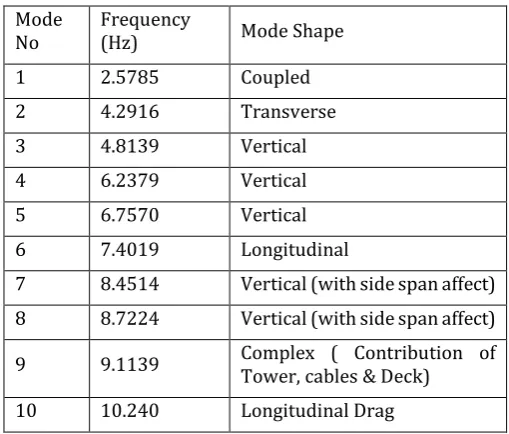
Modal analysis solves the eigenvalues for the structures. For this modal Block Lanczos method is used which works on the basis of eigenvalue and eigenvector extraction technique. Total dynamic response can be studies by several modes of vibrations. The force presence in three perpendicular directions and the coupling effects are considered in the modal analysis. However, to differentiate between the simple vertical, transverse and torsional modes is difficult due to the coupling effects. For the 3-D modal bridge all the possible mode shapes are obtained to study the dynamic behavior of the cable stayed bridges. First ten mode shapes are given in the Table-1, showing the frequencies of the modal bridge.
Table -1: Mode Shapes and Related Frequencies
Mode
No Frequency (Hz) Mode Shape
1 2.5785 Coupled
2 4.2916 Transverse
3 4.8139 Vertical
4 6.2379 Vertical
5 6.7570 Vertical
6 7.4019 Longitudinal
7 8.4514 Vertical (with side span affect)
8 8.7224 Vertical (with side span affect)
9 9.1139 Complex ( Contribution of Tower, cables & Deck)
10 10.240 Longitudinal Drag
[image:5.595.306.561.433.650.2]© 2017, IRJET | Impact Factor value: 6.171 | ISO 9001:2008 Certified Journal
| Page 2042
Fig- 7: 1st Modal ShapeFig- 8: 2nd Modal Shape
Fig- 9: 3rd Modal Shape
© 2017, IRJET | Impact Factor value: 6.171 | ISO 9001:2008 Certified Journal
| Page 2043
Fig- 11: 5th Modal ShapeFig- 12: 6th Modal Shape
Fig- 13: 7th Modal Shape
© 2017, IRJET | Impact Factor value: 6.171 | ISO 9001:2008 Certified Journal
| Page 2044
Fig- 15: 9th Modal ShapeFig- 16: 10th Modal Shape
Mode shapes shows that vertical direction is the most flexible direction in cable stayed bridges. The upward and downward movement of the bridge deck induces slight bending in the longitudinal direction. First mode shows the coupled vibration behavior between the vertical and longitudinal direction because no movement is observed in
transverse direction. 2nd mode shape shows motion in
transverse direction. 4th and 5th mode shapes are related to
the vertical movement of the girder. In 6th mode shape the
contribution of the cable is dominant which tends to bend
the tower in longitudinal direction. From 7th and 8th mode
shapes the effect of the side spans or approaches can be
seen. 9th mode shape represents the complex mode shape
which include the effects of cables, tower and the deck system. Drag or longitudinal bending can be seen in 10th
mode shape.
4.3 TIME HISTORY ANALYSIS AND RESPONSE OF THE CABLE-STAYED BRIDGE
Time history analysis is performed for the given finite element model of the bridge under earthquake excitation forces to study the behavior and response of the different components of the cable stayed bridges. For this purpose typical moderate earthquake, El Centro (1940), data is used. The peak ground acceleration (PGA) for this earthquake is 0.348 m/s2 and the frequency is 1.75 Hz. Time history records for the earthquake data is given in X, Y and Z directions is given in Fig-17 to Fig-19.
Fig- 17: El Centro Earthquake X direction Ground Motion
© 2017, IRJET | Impact Factor value: 6.171 | ISO 9001:2008 Certified Journal
| Page 2045
Fig- 19: El Centro Earthquake Z direction Ground Motion4.3.1. DECK GIRDER BEHAVIOR
The bridge is analyzed for all three directions of the earthquake data. The peak deflection response of the deck girder at the mid-span is shown in Fig-20 to Fig-25.
Fig- 20: Peak Vertical Displacement of deck at the Mid-span
Fig- 22: Peak Longitudinal Displacement at the Mid-span
Fig- 23: Vertical Displacements at the Middle of Right Span
Fig- 21: Peak Transverse Displacement of deck at the Mid- span
© 2017, IRJET | Impact Factor value: 6.171 | ISO 9001:2008 Certified Journal
| Page 2046
Fig- 25: Longitudinal Displacements at the Middle ofRight Span
Peak displacements for the girder at different locations is given in the figures and tabulated in Table-2. The maximum deflections are recorded in vertical direction for this bridge model. This confirms that these types of bridges are more flexible in vertical and transverse direction than longitudinal direction. The results for the right and left span were found almost similar and can be seen in Table-2.
Table-2: Peak Displacements of the Deck girder at Mid Span for the El Centro Earthquake
Girder
Portion Vertical Displacemen ts (cm)
Transverse Displacemen ts (cm)
Longitudinal Displacemen ts (cm)
At Towers 27 20.2 7.4
Right Mid
Span 13.8 6.7 2.23
Left Mid
Span 12.6 6.4 2.22
4.3.2. TOWER BEHAVIOR
The displacements observed under these earthquake loadings for some important portions of the tower can be seen in Fig-26 to Fig-28.
Fig- 26: Vertical Displacements at Tower Top
Fig- 27: Transverse Displacements at Tower Top
© 2017, IRJET | Impact Factor value: 6.171 | ISO 9001:2008 Certified Journal
| Page 2047
Tower response in transverse and longitudinal direction can be seen in Table-3.
Table-3: Peak Displacements of Tower
Tower Portion Vertical
Displaceme nts (cm) Transverse Displaceme nts (cm) Longitudin al Displacem ents (cm)
Tower Top 6.9 33.2 30.1
At Girder level 6.8 24.8 24.2
1 m Above
Tower Bottom 8.3 5.3 4.1
Some observations based on the time history analysis of the structure are as:
The peak responses of the bridge do not always occur under the higher earthquake acceleration. It depends on the characteristics of the earthquake excitations, modal characteristics and the distribution of the mass along with the stiffness. The general response of the bridge is satisfied from the displacement values. The bridge is seen to be more flexible in vertical direction.
5.
CONCLUSIONS
In this study a detailed 3-D model was developed and analyzed for the dead loads and dynamic loads. Both static analysis (nonlinear) and dynamic analysis (modal and time history response) were performed in order to check the response of the bridge. From the above analyses some major conclusions can be made.
1. To provide sufficient degree of constraints, it is better
to use single element (truss/link) for the cables instead of multiple elements. However, single element member are comparatively weak but their connection with tower and girder make them feasible to be analyzed under static and dynamic loads.
2. It is difficult to develop a complete 3-D nonlinear
model. With the decrease in the element size or the computational work increases and the convergence problem arises. For a model with very small elements the convergence may not be achieved.
3. Iteration can be controlled by choosing the
displacement convergence instead of the default force convergence of ANSYS.
4. The sources of nonlinearities in the model created are
mostly geometric like the sagging effect of the cables and girder cross-section.
5. The deflections under the dead loads were observed
to be very small. So the initial deformed shape under these loads can be neglected.
6. Self-weight of the structure plays a key role in overall
stiffness of the cable stayed bridges. With the increase
in dead load the stiffness of the structure can be improved. So modal analysis without the effects of the dead loads will give relatively safe structure as it underestimate the stiffness of the cable stayed bridges. So the modal analysis must be pre-stressed in order to include the more realistic stiffness of the structural elements.
7. The modal shapes and the time history analysis
results show that the lateral stiffness and the longitudinal stiffness of the cable stayed bridges are larger than the vertical stiffness.
8. The approach spans weakly interact during the
earthquake due to their high stiffness as compared to the main span of the bridge.
9. From the time history analysis it is observed that the
stronger responses are not always due to the higher peak accelerations of the earthquake excitation forces. It depends on the excitations properties, modal properties and the distribution of the mass of the structure.
10. Cables mostly show elastic behavior under
earthquake and they are subjected to axial tensile forces. So cables can be considered as linear elements during the earthquake analysis.
REFERENCES
1. Gimsing, N.J. and C.T. Georgakis, Cable supported
bridges: concept and design. 2011: John Wiley & Sons.
2. Treyger, S., et al. Seismic design of the new Tacoma
Narrows Bridge. in Proc., The 11th Int. Conf. on Soil Dynamics & Earthquake Eng., and The 3rd Int. conf. on Earthquake Geotechnical Eng. 2004.
3. ARZOUMANIDIS, S., A. SHAMA, and S. MARLOW,
SEISMIC PERFORMANCE OF THE NEW TACOMA NARROWS BRIDGE. 2004.
4. Fleming, J.F. and E.A. Egeseli, Dynamic behaviour of
a cable‐stayed bridge. Earthquake Engineering & Structural Dynamics, 1980. 8(1): p. 1-16.
5. Nazmy, A.S. and A.M. Abdel-Ghaffar,
Three-dimensional nonlinear static analysis of cable-stayed bridges. Computers & structures, 1990. 34(2): p. 257-271.
6. Abdel-Ghaffar, A.M. and A.S. Nazmy, 3-D nonlinear
seismic behavior of cable-stayed bridges. Journal of Structural Engineering, 1991. 117(11): p. 3456-3476.
7. Parvez, S. and M. Wieland. Earthquake Behaviour of
© 2017, IRJET | Impact Factor value: 6.171 | ISO 9001:2008 Certified Journal
| Page 2048
International Conference on Cable-stayed Bridges, Bangkok, Thailand. 1987.
8. Karoumi, R. Modeling of cable-stayed bridges for
analysis of traffic induced vibrations. in Proc., IMAC-XVIII Conf. on Structural Dynamics. 2000.
9. Shen, X., et al., Seismic performance of Transverse
Steel Damper seismic system for long span bridges. Engineering Structures, 2017. 141(Supplement C): p. 14-28.
10. Li, S., et al., Seismic responses of super-span
cable-stayed bridges induced by ground motions in different sites relative to fault rupture considering soil-structure interaction. Soil Dynamics and Earthquake Engineering, 2017. 101(Supplement C): p. 295-310.
11. Kang, X., et al., Seismic damage evaluation of
high-speed railway bridge components under different intensities of earthquake excitations. Engineering Structures, 2017. 152(Supplement C): p. 116-128.
12. Atmaca, B., M. Yurdakul, and Ş. Ateş, Nonlinear
dynamic analysis of base isolated cable-stayed bridge under earthquake excitations. Soil Dynamics and Earthquake Engineering, 2014. 66(Supplement C): p. 314-318.
13. Habib, M., Analysis of Dynamic Behavior of a
Single-Tower Cable Stayed Bridge. 2014, Huazhong University of Science and Technology China.
14. ANSYS, C., Help Manual 12.1.
15. Ren, W.-X., Ultimate behavior of long-span
cable-stayed bridges. Journal of Bridge Engineering, 1999. 4(1): p. 30-37.
16. Zhu, L.D., H.F. Xiang, and Y.L. Xu, Triple-girder
model for modal analysis of cable-stayed bridges with warping effect. Engineering Structures, 2000. 22(10): p. 1313-1323.
17. Tuladhar, R., W.H. Dilger, and M.M. Elbadry,
Influence of cable vibration on seismic response of cable-stayed bridges. Canadian journal of civil engineering, 1995. 22(5): p. 1001-1020.
18. Bangash, M., Concrete and concrete structures:
Numerical modelling and applications. 1989.
19. Siringoringo, D. and Y. Fujino. Response Analysis of