© 2017, IRJET | Impact Factor value: 5.181 | ISO 9001:2008 Certified Journal | Page 270
TAGUCHI BASED OPTIMIZATION OF CUTTING PARAMETERS
ALUMINIUM ALLOY 6351 USING CNC
Mahendra Singh
1, Amit Sharma
2, Deepak Juneja
3, Anju Chaudhary
41
Assistant Professor, Department of Mechanical Engg, MIET, Meerut, UP, INDIA
2
Assistant Professor, Department of Mechanical Engg, GEC, Naultha , Panipat , Haryana, INDIA
3
Head, Department of Mechanical Engg, GEC,Naultha , Panipat,Haryana, INDIA
4
Assistant Professor, Department of Mechanical Engg, MIET , Meerut, UP,INDIA
---***---Abstract
- Aluminum and its alloys are extensively used in wide variety of applications including domestic utensils, electronic circuits, structural applications, automobile industries etc. Aluminum alloys tend to lose their strength when they are exposed to temperatures of about 200-250°C. However strength of Aluminum alloys increases at freezing temperatures. They have high strength to weight ratio. Hence, the aluminum alloy6351 is used in manufacturing of tubes and pipes. Machining operation on Al 6351 are performed and cutting parameters i.e. feed rate, depth of cut and spindle speed have been optimized for Metal removal rate (MRR) and Surface Roughness by using Taguchi technique. CNC Lathe machine is used for turning operation in order to determine Metal Removal Rate (MRR) and Tele Surf tester is used to measure the surface roughness. It is observed that feed rate is the most influencing factor for metal removal rate (MRR) followed by depth of cut and speed. Whereas in case of surface roughness, feed is observed as most prompting factor with respect to the quality aspects of surface roughness followed by speed and depth of cut.Key Words
:
Al 6351, CNC Lathe, TalySurf Tester, MRR, Surface Roughness, Machining time, Mini tab-17, ANOVA, S/NRatio
1. INTRODUCTION
The turning is the most widely used cutting process among all the processes. The increasing importance of turning operations is gaining new heights in the present industrial age, in which parts are made in round shape by a single point cutting tool on CNC lathe. Surface roughness is used to check the quality of a product, is one of the major quality characteristics of a turning product. In order to get better surface finish, the appropriate selection of cutting parameters is important before investigation. Material removal rate is also main characteristic in turning operation for high rate of production and high material removal rate is constantly required. The present exertion examines the effect of cutting parameters in turning aluminum alloy 6351. Aluminum alloy 6351 is a moderate strength alloy generally referred to as an architectural alloy. It is generally used in manufacturing complicated parts. It has a better surface finish, high corrosion fighting, good weld capability and it can be easily anodized. Aluminum alloy 6351 is usually used in architectural applications, extrusions, window frame works, entryways, shop fittings, watering system tubing. The experiments are considered utilizing Taguchi's technique with the three process parameters i.e. cutting speed, feed rate, and depth of cut at three levels. The outcomes are optimize according to parameter setting to gain minimum surface roughness and maximum material removal rate.
2. STEPS OF METHODOLOGY ADAPTED
1. Initial study to determine the various controlled and uncontrolled parameters 2. Selection of work materials, tool materials and their combination based on literature 3. Selection of process parameters, responses and their levels
4. Selection of experimental layout using Taguchi method
5. Conduction of experiment with different work tool material combination to study and measure various performance characteristics like surface roughness, material removal rate and machining accuracy
6. Measurement of response using standard equipments
7. Parameter optimization using Taguchi method and analysis of data using statistical tools. 8. Creating mathematical models by multiple regression analysis using Minitab-17 Software
© 2017, IRJET | Impact Factor value: 5.181 | ISO 9001:2008 Certified Journal | Page 271
3. WORK MATERIAL
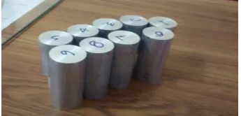
[image:2.595.198.371.150.233.2]Aluminum alloy 6351 is selected because of its low weight to strength ratio, better surface finish and its large number of applications in different areas such as extrusions, window outlines, entryways, shop fittings, watering system tubing etc.
Fig -1: Aluminum alloy 6351
Table -1: Chemical Composition of Al 6351
4. DEGREE OF FREEDOM
Number of parameters = 3Number of levels for each parameters = 3
Total degree of freedom (DOF) for 3 parameters = 3x (3-1) = 6
Minimum number of experiment = Total degree of freedom for parameters + 1 Minimum number of experiments = 6+1
Minimum number of experiments = 7
For the above process parameters and their levels, the minimum numbers of experiments to be conducted are 7. So that is why nearbyL9 orthogonal array is taken.
5. PROCESS PARAMETERS AND THEIR LEVELS
The cutting parameters and their levels are considered for the studies are set in the given table.
Table -2: Machining parameters and their levels
Parameters
Levels
level 1 level 2 level 3
Speed (m/min) 500 800 1100
Feed (mm/rev) 0.10 0.20 0.30
DOC (mm) 0.20 0.25 0.30
Elements Weights
Al Remainder
Si 0.83
Cu 0.037
Mn 0.49
Mg 0.67
Cr 0.01
Zn 0.02
© 2017, IRJET | Impact Factor value: 5.181 | ISO 9001:2008 Certified Journal | Page 272
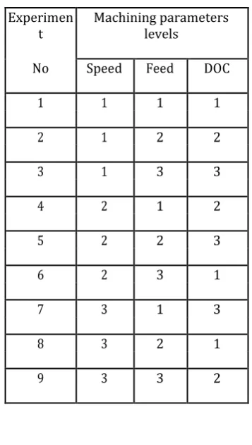
6. ORTHOGONAL ARRAY EXPERIMENT
Table -3: Experimental layout of L9 orthogonal array
Experimen
t Machining parameters levels
No Speed Feed DOC
1 1 1 1
2 1 2 2
3 1 3 3
4 2 1 2
5 2 2 3
6 2 3 1
7 3 1 3
8 3 2 1
9 3 3 2
7. PROCESS
Fig -2: Dimensions of work piece after machining
1. On nine work pieces of Al 6351 the experiment is carried out.
2. All the work pieces are turned on CNC machine. The dimensions of each work piece is [Total length of work piece (L) =70 mm, Initial Diameter (D) =30 mm, Turned length of work piece (l) =25 mm & final diameter (d) =20 mm]
3. For each work piece time is measured with the help of stop watch.
4. By using the initial & final diameters and machining time, material removal rate is calculated by using the formula.
Where, D =Work piece diameter before turning in mm, d = Work piece diameter after turning in mm, L =Work piece length in mm.
[image:3.595.203.389.466.541.2]© 2017, IRJET | Impact Factor value: 5.181 | ISO 9001:2008 Certified Journal | Page 273
8. ANALYSIS OF S/N RATIOS
The S/N ratio is the tool which measures the performance of particular process parameters with respect to the surface roughness and material removal rate. The S/N ratio for surface roughness and MRR has been calculated using smaller the better and larger the better characteristics.
[image:4.595.224.373.272.420.2]Table [4] and [5] shows the responses for S/N ratios of smaller the better and larger the better.
Table -4: Response table for S/N ratios, smaller is better
Level Speed Feed DOC
1 -5.638 2.762 -6.854
2 -3.301 -4.01 -4.983
3 -7.895 -15.587 -4.998
Delta 4.594 18.349 1.87
Rank 2 1 3
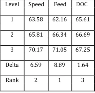
Table -5: Response table for S/N ratios, larger is better
Level Speed Feed DOC
1 63.58 62.16 65.61
2 65.81 66.34 66.69
3 70.17 71.05 67.25
Delta 6.59 8.89 1.64
Rank 2 1 3
[image:4.595.221.375.472.622.2]© 2017, IRJET | Impact Factor value: 5.181 | ISO 9001:2008 Certified Journal | Page 274
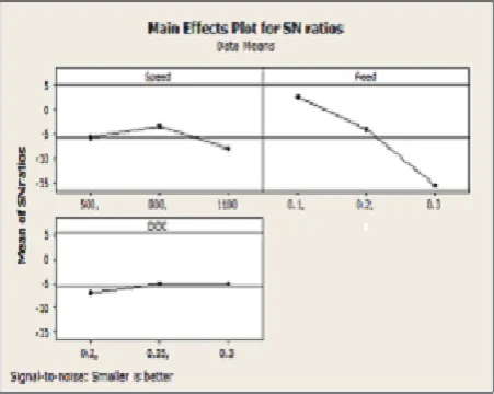
9. MAIN EFFECT PLOTS ANALYSIS FOR SURFACE ROUGHNESS & MRR
Fig -3: Main effect plots S/N ratios for surface roughness
Fig -4: Main effect plots S/N ratios for material removal rate
The main effect plot for S/N ratios is indicated in fig [3] this figure demonstrates the variation of individual response with speed, feed rate, and depth of cut parameters respectively. The main effects plots are used to emphasis the optimal conditions for surface roughness. As showed by this main effect plot, the optimal conditions for least surface roughness are speed at level 2 (800 rpm), feed at level 1 (0.1 mm/sec) and depth of cut at level 3 (0.3mm).
The main influence plot for S/N ratios is specified in fig [4] this figure determines the difference of individual response with speed, feed rate, and depth of cut factors respectively. The main effects plots are utilized to emphasis the optimal conditions for material removal rate. As shown in this main effect plot, the best conditions for high material removal rate are speed at level 3 (1100 rpm), feed at level 3 (0.30 mm/sec) and depth of cut at level 3 (0.30 mm).
10. ANALYSIS OF VARIANCE (ANOVA)
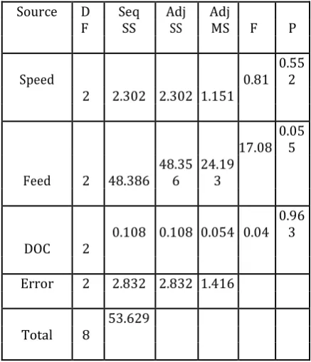
[image:5.595.185.411.335.515.2]© 2017, IRJET | Impact Factor value: 5.181 | ISO 9001:2008 Certified Journal | Page 275 Table -6: ANOVA table for S/N ratios of surface Roughness
Source D Seq Adj Adj
F SS SS MS F P
Speed 0.81 0.552
2 2.302 2.302 1.151
17.08 0.055
Feed 2 48.386 48.356 24.193
0.108 0.108 0.054 0.04 0.963
DOC 2
Error 2 2.832 2.832 1.416
53.629 Total 8
Table -7: ANOVA table for S/N ratios of material removal rate
Sourc
e D Seq Adj Adj F P %
F SS SS MS C
Speed 2 4474648 447464 2237324 103.81 0.001 0.010
Feed 2 7819922 781992 3909961 181.42 0.0 0.005 00
DOC 2 141507 141507 70754 3.28 0.023 0.233
Error 2 43104 43104 21552
Total 8 12479181
It is obvious from table [6] that feed (P=0.055) is the most effective parameter on the surface roughness followed by speed (P=0.552) and depth of cut (0.963) being recorded as the least effective parameter.
[image:6.595.192.406.398.681.2]© 2017, IRJET | Impact Factor value: 5.181 | ISO 9001:2008 Certified Journal | Page 276
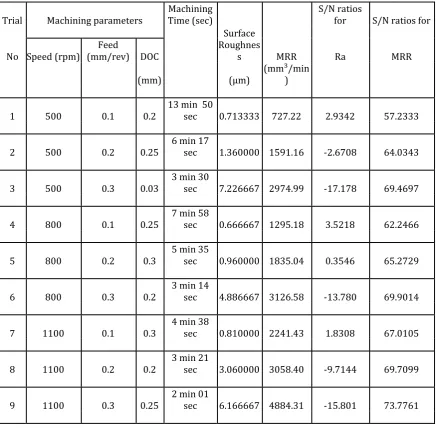
11. ANALYSIS OF EXPERIMENTAL RESULTS
The result is obtained from nine machining experiments for Al6351, designed by Taguchi method. In this study every one of the designs, plots and investigation have been finished applying Minitab-17software.
[image:7.595.61.498.187.615.2]
Table -8: Analysis of experimental results
12. REGRESSION ANALYSIS FOR SURFACE ROUGHNESS & MRR
The regression equation is
Ra = -2.60747 + 0.000409(Speed) +26.81667(Feed) + 1.122223 (DOC)
MRR = -1590.49 + 2.717094(Speed) + 11203(Feed) +464.2(DOC)
Trial Machining parameters Machining Time (sec) S/N ratios for S/N ratios for
No
Surface Roughnes
s MRR Ra MRR
Speed (rpm) (mm/rev) DOC Feed
(mm) (µm) (mm³/min)
1 500 0.1 0.2 13 min 50 sec 0.713333 727.22 2.9342 57.2333
2 500 0.2 0.25 6 min 17 sec 1.360000 1591.16 -2.6708 64.0343
3 500 0.3 0.03 3 min 30 sec 7.226667 2974.99 -17.178 69.4697
4 800 0.1 0.25 7 min 58 sec 0.666667 1295.18 3.5218 62.2466
5 800 0.2 0.3 5 min 35 sec 0.960000 1835.04 0.3546 65.2729
6 800 0.3 0.2 3 min 14 sec 4.886667 3126.58 -13.780 69.9014
7 1100 0.1 0.3 4 min 38 sec 0.810000 2241.43 1.8308 67.0105
8 1100 0.2 0.2 3 min 21 sec 3.060000 3058.40 -9.7144 69.7099
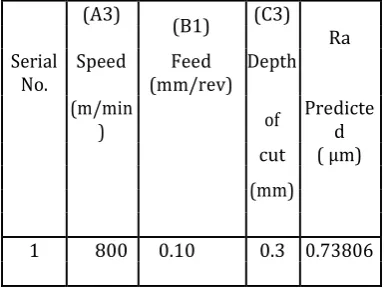
© 2017, IRJET | Impact Factor value: 5.181 | ISO 9001:2008 Certified Journal | Page 277 Table -9: Predicted value for surface roughness
(A3) (B1) (C3)
Speed Depth Ra
Serial
No. (mm/rev) Feed (m/min
) of Predicted
cut ( µm) (mm)
[image:8.595.195.399.302.404.2]1 800 0.10 0.3 0.73806
Table -10: Predicted value for Material removal rate
(A3) (C1) MRR
Serial Speed (B3) Feed Depth Predicted No (mm/rev) of cut
m/min (mm) (mm³/min)
1 800 0.1 0.3 4898.603
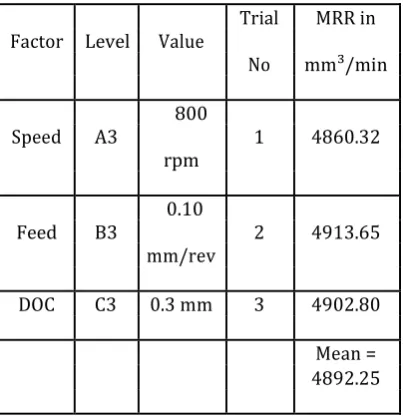
13. CONFIRMATION EXPERIMENT FOR SURFACE ROUGHNESS & MRR
The results after experimenting in three trials are shown in table [11] and table [12]. The mean Ra value = 0.7477 μm and the mean MRR value=4892.25 mm³/min.
Table -11: Results of confirmation experiment for Ra
Factor Level Value Trial No Ra in µm
Speed A3
800 rpm
1 0.7352
Feed B1 0.10 2 0.8001
mm/rev
DOC C3 0.3 mm 3 0.7038
[image:8.595.194.401.513.734.2]© 2017, IRJET | Impact Factor value: 5.181 | ISO 9001:2008 Certified Journal | Page 278 Table -12: Results of confirmation experiment for MRR
Factor Level Value Trial MRR in No mm³/min
Speed A3 800 1 4860.32
rpm
Feed B3 0.10 2 4913.65
mm/rev
DOC C3 0.3 mm 3 4902.80
Mean = 4892.25
When factor values are substituted in the mathematical model regression equation, it has given surface roughness (Ra) value = 0.73806μm and material removal rate (MRR) value = 4898.603 mm³/min. The difference in surface roughness (Ra) and material removal rate (MRR) values observed is only 0.009μm and 6.35 mm³/min which is negligibly small and hence the model is validated.0.73806μm is the value of surface roughness (Ra) and4898.603 mm³/min is the value of material removal rate (MRR). Table [11] and table [12] showing optimal factors level A3B1C3 and A3B3C3 is more or less satisfied.
14. CONCLUSIONS AND FUTURE SCOPE
This presented work is an experimental approach to study the effect of input parameters i.e. spindle speed, feed rate and depth of cut on the surface roughness and material removal rate, the following conclusions can be made after performing experiments.
From response table rankings, it can be concluded that.
1. The feed rate has been found to be the most influencing factor on the quality attributes of surface roughness followed by speed and depth of cut.
2. Optimal parameters setting for surface roughness in turning of aluminum alloy 6351 are A2, B1and C3.
3. The feed rate has been found to have most extreme impact on the material removal rate than followed by depth of cut and speed.
4. Optimal parameters setting for material removal rate in machining of aluminum alloy 6351 are A3, C3 and B
15. FUTURE SCOPE
In this present work only three parameters i.e. speed, feed and doc have been optimized in accordance with their effects. View of future scope, other parameters i.e. nose radius, cutting tool angles etc. can be optimized for MRR and surface roughness. Likewise, the other output parameters i.e. power consumption, tool life, tool wear etc. can be added.
REFERENCES
[1].J.Paulo Davim, (2001). “A note on the determination of optimal cutting conditions for surface finish obtained in turning using design of experiments”. Journal of Material Processing Technology 116,305-308.
[2] Reis DD and Abrão AM.(2005) “The machining of aluminum alloy 6351”. Journal of Engineering Manufacture, 219 Part B
© 2017, IRJET | Impact Factor value: 5.181 | ISO 9001:2008 Certified Journal | Page 279
[4].M.Naga Phani Sastry, K. Devaki Devi, (2011) “Optimizing of Performance Measures in CNC Turning using Design of Experiments (RSM).” Science Insights: An International journal, 1(1):1-5.
[5].H.K.Dave, L.S.Patel, H.K.Raval,(2012) “Effect of machining conditions on MRR and surface roughness during CNC Turning of different Materials Using Tin Coated Cutting Tools-A Taguchi Approach “International Journal of Industrial Engineering Computations3, 925-930.
[6].U.D.Gulhane, B.D. Sawant, P.M.Pawar,(2013) “Analysis of Influence of Shaping Process Parameters on MRR and Surface roughness of Al6061 using Taguchi method. “International Journal of Applied Research and Studies.ISSN:2278-9480 Volume 2, Issue 4.
[7]Chetan Bhardwaj, (2015) “Investigation of Parameters Influencing AL6351 Surface Finish and Material Removal Rate by CNC Wire EDM”. Vol. 2, 2015, pp.120-125.