© 2017, IRJET | Impact Factor value: 5.181 | ISO 9001:2008 Certified Journal | Page 137
WIRELESS SENSOR FOR TRAFFIC CONTROL SYSTEM
Arockia Panimalar.S
1, Hari Priya
2, Kamatchi. K
31
Assistant Professor, Department of BCA & M.Sc SS, Sri Krishna Arts and Science College, Coimbatore, India
2 ,3III BCA, Department of BCA & M.Sc SS, Sri Krishna Arts and Science College, Coimbatore, India
---***---Abstract -
This paper introduces an astute movementcontrol framework to pass crisis vehicles easily. Every individual vehicle is outfitted with exceptional radio recurrence recognizable proof (RFID) tag (set at a key area), which makes it difficult to expel or annihilate. We use RFID peruser, NSK EDK-125–TTL, and PIC16F877A structure on-chip to examine the RFID marks joined to the vehicle. It checks number of vehicles that passes on a particular path in the midst of a predefined term. It additionally decides the system blockage, and henceforth the green light span for that way. If the RFID-tag-read has a place with the stolen vehicle, by then a message is sent using GSM SIM300 to the police control room. Moreover, when a rescue vehicle is moving toward the intersection, it will convey to the movement controller in the intersection to turn ON the green light. This module utilizes ZigBee modules on CC2500 and PIC16F877A framework on-chip for remote correspondences between the emergency vehicle and activity controller. The model was tried under various mixes of contributions to our remote correspondence research facility and test comes about were found obviously.
Key Words
:
ZigBee, CC2500, GSM, SIM300, PIC16F877A,ambulance vehicle, stolen vehicle, congestion control, traffic junction.
1. INTRODUCTION
INDIA is the second most crowded Country in the World and is a quickly developing economy. It is seeing repulsive street clog issues in its urban areas. System advancement is move back when diverged from the improvement in number of vehicles, on account of space and cost goals [1]. Additionally, Indian activity is non-path based and clamorous. It needs an activity control arrangements, which are not quite the same as the created Countries. Smart administration of movement streams can decrease the negative effect of blockage. As of late, remote systems are broadly utilized as a part of the street transport as they give more financially savvy choices [2]. Advancements like ZigBee, RFID and GSM can be utilized as a part of activity control to give financially savvy arrangements. RFID is a remote innovation that utilizations radio recurrence electromagnetic vitality to convey data between the RFID tag and RFID peruser. Some RFID frameworks will just work inside the range inches or centimeters, while others may work for 100 meters (300 feet) or more. A GSM modem is a particular sort of modem, which acknowledges a SIM card and works over a membership to a versatile administrator, much the same as a
cell phone. AT summons are utilized to control modems. These orders originate from Hayes summons that were utilized by the Hayes shrewd modems. The ZigBee works at low-control and can be utilized at all the levels of work designs to perform predefined undertakings. It works in ISM groups (868 MHz in Europe, 915 MHz in USA and Australia, 2.4 GHz in rest of the world). Information transmission rates differ from 20 Kilobits/second in the 868 MHz recurrence band to 250 Kilobits/second in the 2.4 GHz recurrence band [3], [4]. The ZigBee utilizes 11 directs if there should be an occurrence of 868/915 MHz radio recurrence and 16 diverts in the event of 2.4 GHz radio recurrence. It likewise utilizes 2 channel arrangements, CSMA/CA and opened CSMA/CA [5].
The entire paper is gathered into 5 sections. Areas II discuss the writing review. Area III examines about the present issues that exist in clearing a path to a rescue vehicle and different vehicles. It likewise discusses how the proposed model will defeat the issues confronted in creating Countries and in addition created nations. Segment IV gives the execution points of interest of the proposed show. Segment V displays the upgrade of this work.
2. LITERATURE SURVEY
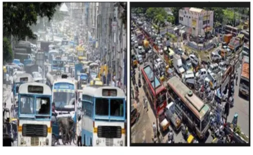
© 2017, IRJET | Impact Factor value: 5.181 | ISO 9001:2008 Certified Journal | Page 138 Fig -1: Traffic in Bangalore City
In such cases, the line of vehicles in a green wave develops in measure until the point when it turns out to be too extensive and a portion of the vehicles can't achieve the green lights in time and should stop. This is brought over-immersion [12], [13].
In [8], the utilization of RFID movement control to stay away from issues that ordinarily emerge with standard activity control frameworks, particularly those identified with picture preparing and shaft intrusion procedures are talked about. This RFID method manages multivehicle, multilane, multi street intersection territories. It gives a proficient time administration conspires, in which, a dynamic time plan is worked out progressively for the entry of each movement segment. The constant operation of the framework copies the judgment of a movement policeman on obligation. The quantity of vehicles in every segment and the directing are legitimacies, whereupon the computations and the judgments are finished. The inconvenience of this work is that it doesn't talk about what techniques are utilized for correspondence between the crisis vehicle and the activity flag controller. In [9], it proposed a RFID and GPS based programmed path freedom framework for emergency vehicle. The concentration of this work is to lessen the deferral in landing of the rescue vehicle to the doctor's facility via naturally clearing the path, in which, emergency vehicle is going, before it achieves the movement flag. This can be accomplished by turning the movement motion, in the way of the emergency vehicle, to green when the rescue vehicle is at a specific separation from the activity intersection. The utilization of RFID recognizes the crisis and non-crisis cases, therefore averting superfluous movement blockage. The correspondence between the rescue vehicle and movement flag post is done through the handsets and GPS. The framework is completely mechanized and requires no human intercession at the activity intersections. The weakness of this framework is it needs all the data about the beginning stage, end purpose of the travel. It may not work, if the rescue vehicle needs to take another course for a few reasons or if the beginning stage is not known ahead of time.
Movement is a basic issue of transportation framework in above all the urban areas of Countries. This is particularly valid for Countries like India and China, where the populace is expanding at higher rate as show in figure 1. For instance, Bangalore city has seen an exceptional development in vehicle populace as of late. Therefore, a number of the blood vessel streets and crossing points are working over the limit (i.e., v/c is more than 1) and normal trip speeds on a portion of the key streets in the focal territories are lower than 10 Km/h at the pinnacle hour. In [10], a portion of the primary difficulties are administration of more than 36,00,000 vehicles, yearly development of 7–10% in movement, streets working at higher limit extending from 1 to 4, travel speed under 10 Km/h at some focal territories in top hours, inadequate or no parking spot for vehicles, set number of policemen. In [11], at present video movement reconnaissance and checking framework appointed in Bangalore city. It includes a manual examination of information by the movement administration group to decide the activity light span in each of the intersection. It will impart the same to the nearby cops for the fundamental activities.
3. PROPOSED MODEL
© 2017, IRJET | Impact Factor value: 5.181 | ISO 9001:2008 Certified Journal | Page 139
3.1. ZigBee Module CC2500
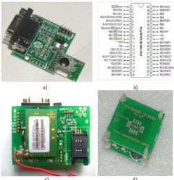
[image:3.595.33.285.244.505.2]The CC2500 is a RF module and has transceiver, which gives a simple approach to utilize RF correspondence at 2.4 GHz. Each CC2500 is furnished with the microcontroller (PIC 16F877A), which contains Unique Identification Number (UIN). This UIN depends on the enrollment number of the vehicle. A standout amongst the most vital components is serial correspondence with no additional equipment and no additional coding. Consequently, it is a transceiver as it gives correspondence in the two headings, however just a single bearing.
Fig -1: PIN diagrams of different components used in our prototype. (a) ZigBee module CC2500. (b) Pin diagram of PIC16F877A. (c) GSM Module SIM300. (d) RFID reader–125 kHz–TTL.
The microcontroller and CC2500 dependably speak with the microcontroller by means of serial correspondence. Rx stick of CC2500 is associated with Tx (RC6) of microcontroller and Tx stick of CXC2500 is associated with Rx stick of microcontroller (RC7). Other two pins are utilized to stimulate transceiver. It is utilized to transmit and get the information at 9600 baud rate. Figure 4.1.a demonstrates the picture of transceiver. Here, we utilizes CC2500 ZigBee module and it has transmission scope of 20 meters.
3.2. Microcontroller (PIC16F877A)
Fringe Interface Control (PIC) 16F arrangement has a great deal of points of interest when contrasted with different arrangement. It executes every direction in under 200 nanoseconds. It has 40 sticks and has 8K program memory and 368 byte information memory. It is anything but difficult
to store and send UINs. At the intersection, it is anything but difficult to store expansive number of crisis vehicles. Before changing to green, it ought to fulfill every one of the conditions. Straightforward intrude on choice gives the favorable position like hop starting with one circle then onto the next circle. It is anything but difficult to switch whenever. It expends less power and works by vehicle battery itself with no additional equipment. Figure 2.b demonstrates the PIN Diagram of PIC16F877A.
3.3. GSM Module SIM 300
Here, a GSM modem is associated with the microcontroller. This enables the PC to utilize the GSM modem to communicate over the versatile system. These GSM modems are most often used to give versatile Internet availability, a considerable lot of them can likewise be utilized for sending and accepting SMS and MMS messages. GSM modem must help a "stretched out AT summon set" for sending/accepting SMS messages. GSM modems are a practical answer for accepting SMS messages, in light of the fact that the sender is paying for the message conveyance. SIM 300 is intended for worldwide market and it is a tri-band GSM motor. It chips away at frequencies EGSM 900 MHz, DCS 1800 MHz and PCS 1900 MHz. SIM300 highlights GPRS multi-space class 10/class 8 (discretionary) and bolsters the GPRS coding plans. This GSM modem is a very adaptable fitting and play quad band GSM modem, interface to RS232, it bolsters highlights like voice, information, SMS, GPRS and inter ground TCP/IP stack. It is controlled by means of AT orders (GSM 07.07, 07.05 and upgraded AT orders). It utilizes AC – DC control connector with following evaluations DC Voltage: 12V/1A.
3.4. RFID Reader–125 kHz–TTL
© 2017, IRJET | Impact Factor value: 5.181 | ISO 9001:2008 Certified Journal | Page 140 utilizes recurrence 125 KHz with a scope of 10 cm.
4. WORKING MODEL
In this model, there are mainly 3 modules as follows.
4.1. Automatic Signal Control System
In this module, for try reason, we have utilized latent RFID labels and RFID peruser with recurrence 125 KHz. RFID tag, when vehicle comes in the scope of the collector will transmit the remarkable RFID to the peruser. The microcontroller associated with the RFID peruser will include the RFID labels read 2 minute span. For testing reason, if the number is more than 10, the green light span is set to 30 seconds, if check is in the vicinity of 5 and 9, the green light term is set to 20 seconds. On the off chance that the number is under 5, the green light span is set to 10 seconds. The red light span will be for 10 seconds and orange light term will be for 2 seconds. Figure 3 usages for programmed flag control and stolen vehicle recognition framework.
4.2. Stolen Vehicle Detection System
In this module, for testing reason, we think about the one of a kind RFID label read by the RFID peruser to the stolen RFIDs put away in the framework. In the event that a match is discovered, at that point the movement flag is instantly swung to red for a span of 30 seconds.
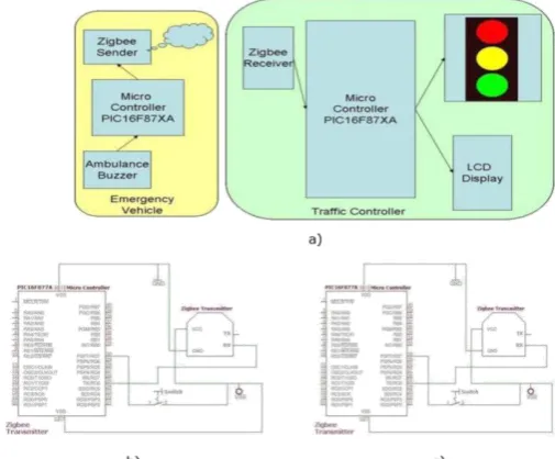
[image:4.595.310.557.51.338.2]Fig-3: Implementation for automatic signal control and stolen vehicle detection system. (a) Block diagram for automatic signal control system. (b) Block diagram for stolen vehicle detection. (c) PIN Diagram for automatic signal control and stolen vehicle detection system.
Fig -4: Implementation for ambulance. (a) Block diagram for emergency vehicle clearance. (b) PIN Diagram for ZigBee transmitter. (c) PIN Diagram for ZigBee receiver.
Likewise a SMS is sent indicating the RFID number by utilizing SIM300 GSM module. The LCD show will demonstrate that stolen vehicle is available as appeared in Figure 3.
4.3. Emergency Vehicle Clearance System
[image:4.595.316.569.412.621.2]© 2017, IRJET | Impact Factor value: 5.181 | ISO 9001:2008 Certified Journal | Page 141 Fig -5:Proposed model images transmitter and receiver. (a)
Pole status at different condition. (b) Transmitter (ZigBee). (c) LCD display at receiver.(d) Detailed image of receiver. (e) When stolen vehicle is detected. (f) Working model
The signal contains extraordinary id and security code. The transmitter contains PIC16F877A microcontroller and ZigBee module. The microcontroller sends the charges and information to the ZigBee by means of serial correspondence. Second part is the collector, which is set at activity post. It additionally contains PIC16F877A microcontroller and ZigBee module. The recipient thinks about the security code got to the security code exhibit in its database. In the event that it matches, at that point it will turn the green light on. For testing reason, we utilized short range RFID peruser in our model. In the first place, the beneficiary part is turned on. The red and green flag will be on for 10 seconds length and orange light will be on for 2 seconds span in a steady progression. Besides, we bring the RFID of stolen vehicle into the scope of RFID peruser. At that point the flag will swing to red for term of 30 seconds and a SMS is gotten. Thirdly, we bring 12 RFIDs into the scope of RFID peruser, and afterward the green light span will change to 30 seconds. Fourthly, we bring a crisis vehicle conveying ZigBee transmitter into the scope of ZigBee beneficiary, and after that the movement light will change to green till the recipient gets the ZigBee motion as appeared in Figure 4.
Figure 5 demonstrates the pictures of various parts and featured elements of the proposed work. Figure 5.a demonstrates the flag shaft introduced in intersection. In the default condition, red and green light will set for 10 seconds. The era will be fluctuated by the movement conditions, stolen vehicle, and crisis vehicle. Figure 5.b demonstrates the transmitter part is set in the emergency vehicle. It transmits ZigBee flag constantly. Figure 5.c demonstrates the LCD show status at various conditions (in that figure one is typical conjunction picture (activity flag running according to the default day and age) and another is LCD show status, when an emergency vehicle drawing close to intersection. Figure 5.d demonstrates the genuine associations of various segments like RFID, GSM, ZigBee, interfacing diverse microcontrollers. Figure 5.e demonstrates the status refreshed at the season of stolen vehicle is found. The stolen vehicle RFID number ought to be refreshed in the database. On the off chance that stolen vehicle is discovered, at that point it will instantly turn on red light in the flag. It sends promptly a message to approved individual. Figure 5.f demonstrates the working model of the proposed work.
5. CONCLUSION AND ENHANCEMENTS
With programmed activity flag control in light of the movement thickness in the course, the manual exertion with respect to the movement policeman is spared. As the whole framework is robotized, it requires less human mediation. With stolen vehicle discovery, the flag consequently swings to red, so the cop can make fitting move, on the off chance that he/she is available at the intersection. Additionally SMS will be sent with the goal that they can get ready to get the stolen vehicle at the following conceivable intersections. Crisis vehicles like emergency vehicle, fire trucks, need to achieve their goals at the most punctual. On the off chance that they invest a great deal of energy in congested driving conditions, valuable existences of many individuals might be in threat. With crisis vehicle freedom, the movement flag swings to green as long as the crisis vehicle is holding up in the activity intersection. The flag swings to red, simply after the crisis vehicle goes through. Advance improvements should be possible to the model by testing it with longer range RFID perusers. Additionally GPS can be put into the stolen vehicle discovery module, with the goal that the correct area of stolen vehicle is known. As of now, we have actualized framework by thinking of one as street of the activity intersection. It can be enhanced by reaching out to every one of the streets in a multi-street intersection.
REFERENCES
[1] G. Varaprasad and R. S. D. Wahidabanu, “Flexible routing algorithm for vehicular area networks,” in Proc. IEEE Conf. Intell. Transp. Syst. Telecommun., Osaka, Japan, 2010, pp. 30– 38
[image:5.595.34.289.67.435.2]© 2017, IRJET | Impact Factor value: 5.181 | ISO 9001:2008 Certified Journal | Page 142 [3] K. Sridharamurthy, A. P. Govinda, J. D. Gopal, and G. Vara
Prasad, “Violation detection method for vehicular ad hoc network-ing,” Security Commun. Netw., to be published.[Online].Available: http://onlinelibrary.wiley.com /doi/10.1002/sec.427/abstract
[4] M. Abdoos, N. Mozayani, and A. L. C. Bazzan, “Traffic light control in non-stationary environments based on multi agent Q-learning,” in Proc. 14th Int. IEEE Conf. Intell. Transp. Syst., Oct. 2011, pp. 580–1585.
[5]ZigBee Specifications, ZigBee Alliance IEEE Standard 802.15.4k2013,2014.[Online].Available: http://www.zigbee. org /Specifications.aspx
[6]Traffic Congestion in Bangalore—A Rising Concern. [Online]. Available: http://www.commonfloor.com /guide/ traffic-congestion-in-bangalore-a-rising-concern-27238.html accessed 2013
[7] A. K. Mittal and D. Bhandari, “A novel approach to implement green wave system and detection of stolen vehicles,” in Proc. IEEE 3rd Int. Adv. Comput., Feb. 2013, pp. 1055–1059.
[8] S. Sharma, A. Pithora, G. Gupta, M. Goel, and M. Sinha, “Traffic light priority control for emergency vehicle using RFID,” Int. J. Innov. Eng. Technol., vol. 2, no. 2, pp. 363–366, 2013.
[9] S R. Hegde, R. R. Sali, and M. S. Indira, “RFID and GPS based automatic lane clearance system for ambulance,” Int. J. Adv. Elect. Electron. Eng., vol. 2, no. 3, pp. 102–107, 2013. [10] P. Sood. Bangalore Traffic Police-Preparing for the Future.[Online].Available:http://www.intranse.in/its1/sites /default/files/D1-S2-, accessed 2011.
[11]Traffic Management Centre. [Online]. Available: http://www. bangaloretrafficpolice.gov.in/ index.php? option=com_content&view=article&id=87&btp=87, accessed 2014.
[12] G. Varaprasad, “High stable power aware multicast algorithm for mobile ad hoc networks,” IEEE Sensors J., vol.
13, no. 5, pp. 1442–1446, May 2013.