http://dx.doi.org/10.4236/wjet.2016.43049
Calculations of Heat Transfer in Torch
Furnaces by Gas Volume Radiation Laws
A. N. Makarov
Chair of Electric Power Supply and Electrical Engineering, Tver State Technical University, Tver, Russia
Received 23 May 2016; accepted 22 August 2016; published 25 August 2016
Copyright © 2016 by author and Scientific Research Publishing Inc.
This work is licensed under the Creative Commons Attribution International License (CC BY).
http://creativecommons.org/licenses/by/4.0/
Abstract
The results stemming from the calculation of heat transfer in torch furnaces by the laws, relating to radiation from solid surfaces and gas volumes are analyzed. The article presents the laws for radiation from gas volumes and the procedure for calculating heat transfer in torch furnaces, fire boxes, and combustion chambers, elaborated on their basis. The example of heat transfer calcula-tion in a torch furnace is given, and it is significantly non-uniform in nature. Non-uniformity of heat flux distribution on heating surfaces is given. According to the results of calculations, a new furnace is designed to decrease the non-uniformity of ingot heating, fuel rate, and increase the furnace capacity. The calculation results of the distribution of heat fluxes on the heating surfaces are given in changing torch geometric dimensions. These results are confirmed by experimental studies.
Keywords
Heat Transfer, Gas Volumes, Heat Radiation Laws, Torch, Furnace
1. Introduction
At present about 40% of all steel in the world is melted in arc steel melting furnaces. Before 1978 an electric arc represented “black box” in arc steel melting furnaces (ASFs), uninvestigated radiating volume ionized gas body.
house, Moscow, 1992 [1]. The monograph [1], as well as a textbook [2], has been used for university training on “Metallurgy” in Russia and neighboring countries.
The theory of heat transfer was published in the form of monograph [1] in “Energoatomizdat” publishing house, Moscow, 1992. Since 1992 this monograph [1], as well as the textbook [2] since 2014 was in use for training students of metallurgy of all the chairs of metallurgy of Russia and near abroad. The monograph [1] and the textbook [2] are used for calculating energy-efficient furnace operations at Russian metallurgical plants. The theory was further developed by the author of this article with disclosure of the laws for heat radiation from gas volumes and development on their basis modern theory of heat transfer in torch furnace, fire boxes, and com-bustion chambers. The disclosed laws for heat radiation from gas volumes, and Makarov’s laws represent a con-tinuation of the theory for heat radiation and stand with the laws for heat radiation from solid bodies, laws of Planck, Wien, Stefan-Boltzmann in importance. The use of the laws for heat radiation from gas volumes and the theory for heat transfer in electric arc and torch furnaces, fire boxes, combustion chambers, developed on their basis allows the researches from tens of countries worldwide to create hundreds of new highly efficient electric arc steel melting furnaces, fire boxes, combustion chambers and save millions of tons of liquid, gas, pulverized fuel and millions of kilowatt of hours of electric energy.
2. Laws of Radiation from Surfaces and Gas Volumes
2.1. Laws of Radiation from Surfaces
In the 19th early 20th century, solid fuel (slantsy, coal, peat, and wood) was fired in furnaces, fire boxes on fire grates. The disclosure of laws of radiation from solid bodies by Planck, Stefan, Boltzmann, Kirghoff, Wien be-longs to this period of time. The laws of radiation from solid bodies cover adequately solid bodies irradiation processes in furnaces, fire boxes, combustion chambers. Since solid bodies radiate by surface, two-dimensional models were used for calculating their radiation. Surfaces emittance are described by integral and differential equations, whose solution can be derived using the double simulation. Solution of double integrals of differential equations describing bodies radiation emitted by the surface is no difficulty. In the 19th early 20th centuries when solving double integrals, analytical expressions, formulas for calculating the radiation heat transfer from one surface to another in any of their attitude were obtained [3]-[7].
Ludwig Boltzmann and Max Planck solved integral and differential equations what resulted in derivation of analytical equations, formulas bearing their names. Thus integral and differential equations of heat transfer are regarded as intermediate values of mathematical calculations.
If it is possible to obtain the solution to the integral and differential equations, we solve them and obtain ana-lytical expressions, formulas.
In the formulas the relationship is viewed to be between the parameters of physical phenomenon and the ob-ject, that does not exist in the integral and differential equations.
Analytical expressions, formulas are obvious and widely available for the calculations, both for the scientists and the students. The advantages of the analytical expressions over the integral and differential equations are in public and beyond controversy. The laws of radiation were used in the 19th-20th centuries and continue to be used for calculating radiative heat transfer in furnaces, fire boxes, combustion chambers.
It was in the 20th-21st century widespread practice to flare gas, liquid, pulverized fuel.
Flaring of fuel is characterized by volume radiation, three-dimensional model of radiation. Quadrillions of particles, 1 × 10¹⁹ - 1 × 1030 radiate in the torch, depending on its power. Gas volumes radiation is described by the integral and differential ternary equations of heat transfer. To solve heat transfer equations, we need triple integration by the height, width, and depth when simulating gas volume by the rectangular parallelepiped as modified: height, width, and depth of the rectangular parallelepiped.
Throughout the 20th century scientists tried to solve triple integral equations, describing radiation from gas volumes. However, the solution to the triple integrals was not found in the 20th century. With the appearance of computers in the 1940s, the programmers were charged to solve the integral equations of heat transfer in torch furnaces, fire boxes, combustion chambers.
In the 1940-2000s hundreds of programs for computer numerical modeling of radiative heat transfer in torch furnaces, fire boxes, combustion chambers were established.
Elec-tric Arc Torch Furnaces and Energy Plants (Lan’, Saint-Petersburg, 2014, 384 p) [In Russian].
Computer numerical methods for calculating heat transfer in torch furnaces, fire boxes, combustion chambers use Canada, French, American scientists (Michael F. Modest, Theodor L. Bergmann, Frank P. Incropera, David P.De Witt, Warwick, Gutson, Jose Pontes, André Garcia McDonald, Hugh Magand and others). Computer nu-merical methods for calculating heat transfer in torch furnaces, fire boxes, combustion chambers are used by in-dustrial corporations. Computer numerical methods for calculating radiation from torch and plasma are used by M. F. Jukov, I. M. Zasypkin, A. N. Leontiev and other scientists.
All the above mentioned authors and corporations use, as a rule, their own developed computer numeric cal-culation programs of the heat transfer integral equations in torch furnaces, fire boxes, combustion chambers. This method provides to divide surfaces and volumes into calculated zones with certain temperatures and optical constants. In case of surface and volume zones radiation fluxes and zone temperatures are computer calculated using the method for discrete approximation of radiation heat transfer integral equations. In this method for cal-culating we use approximate mass of temperatures and optical coefficients of surface and volume zones, that af-fects calculation accuracy. The uncertainty in calculations is 10 - 40 percent. Programs for heat transfer comput-er calculating in furnaces, fire boxes, combustion chambcomput-ers belongs to the organizational secrecy, the validity of programmed calculation cannot be verified for the reasons of program closeness.
A computer, operating with the overwhelming data, can create illusions of phenomenon inclusiveness under study. In actuality the computer promotes propagation of details and particulars of the studied phenomenon, at-taching importance to the special cases. Computer amount of calculations cannot be verified. The calculations, that defy verification raise the doubts. To agree with them would simply believe the authors. One of the found-ers of synergetic (the science of coordinated behavior of many elements as a whole within a complex system) the famous physicist Hermann Haken said that the information, overloaded by the huge number of obscurating details is necessary to compress and turned into a small number of laws, concepts, ideas.
2.2. Laws of Radiation from Gas Volumes
In 1996-2001 the author Makarov A. N. disclosed the laws of radiation from large gas volumes [8][9]. The es-sence of the disclosure consists in the following: isothermal cylinder radiative gas volumes are inscribed in gas radiant gas volumes generated during flame combustion of fuel. The study of isothermal isochoric coaxial cy-linder radiant gas volumes allowed us to establish the following laws of their radiation (Figure 1):
1) The view factors of radiation from volumes falling on the calculation area are equal. 2) The densities of radiation fluxes from volumes falling on the calculation area are equal.
3) The density of radiation flux falling on the calculation area from all the hollow coaxial cylindrical gas vo-lumes is equal to the density of radiation flux from central continuous cylindrical volume of a small diameter at the radiation power releasing in it equal to the total radiation power releasing in all coaxial cylindrical volumes.
[image:3.595.123.497.539.707.2]4) The average path lengths of beams falling on the calculation area from all radiant particles of each volume are equal; the average path length of beams falling on the calculation of all radiant particles is equal to the
arithmetic mean distance from the symmetry axis of volumes to the calculation area.
Regularities, a certain harmonious order in the chaos were first revealed in a chaotic radiation from quadril-lions of particle, that make up the torch. It allows to calculate heat transfer and take into account when calculat-ing the radiation from all the particles and every separate particle on the calculated area in a furnace, fire box, combustion chamber. The demonstration of these laws and their experimental verification are given by the au-thor of discovery in [10]-[14].
The disclosed laws of heat radiation from gas volumes allow to develop model of a torch and modern theory of heat transfer in torch furnaces, fire boxes, combustion chambers. Based on the new method, we carry out calculations of heat transfer in torch furnaces, fire boxes, combustion chambers the calculation results agree well with the measurement results of heating fluxes, temperatures in furnaces, fire boxes, combustion chambers. The modern theory and the procedure for calculating heat transfer in torch furnaces, fire boxes, combustion cham-bers, developed by the author of this article was verified and the results of calculations are confirmed by expe-rimental studies [2].
3. Example of Heat Transfer Calculation in Torch Furnace by Gas Volume
Radiation Laws, Makarov’s Laws
3.1. Design of a Torch Heating Furnace
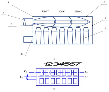
Let us use the torch model as a radiating cylinder for calculating heat transfer in torch heating furnace. Let us calculate heat transfer in a recuperative heating pit with one top burner and air injection from recuperators. Hole chamber 1 is a right parallelepiped with a length of 8 m, width of 3 m, height of 4 m (Figure 2).
Axis O1O2 of a torch 2 and the burner 3, located on the front wall 4 is placed in parallel with the furnace cover 5 and separated from it for a distance of 0.8 m. Fourteen ingots of 7 t in weight and 2.4 m in height are arranged in two columns and seven rows in the working space of the furnace from the front 4 and rear 6 walls. The lower part of the front wall of the furnace 4 disposed channels 8 for removing flue gases from the working space of the
(a)
[image:4.595.132.496.396.702.2](b)
Figure 2. Organization of a workspace of a heating pit (а) and ingot arrangement in it, top view (b)
I-VII-series numbers of ingots.
1
234567
Î
3Î
1Î
4Î
2 O3O1
pit. Fuel is a mixture of natural and blast furnace gases with the heating value r 8 MJ m3
i
Q = . Fuel
consump-tion В = 1890 m3/h. The fuel is heated in a metal tubular recuperator to the temperature tf = 257˚C. The final temperature of heating ingots tf = 1200˚C. The air is heated in a ceramic recuperator to the temperature ta = 776˚C, air flow coefficient α = 1.1.
We take moderate soot density in the torch of the heating pit as μ = 1 gm/m3, particles diameter as d = 0.815 µm, density as ρ = 2 × 10³ kg/m3[2]. The reduction factor of a sooty medium in a heating pit we determine from the equation [2]:
(
)
1.5 r 0.92
к= µ d ρ = (1)
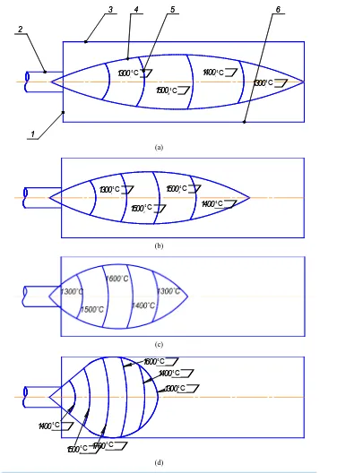
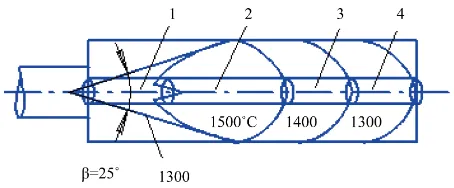
The torch fills free space of a pit of 1.6 m height from the cover to ingot surface (Figure 2). The products of combustion fill the lower part of the pit, free space between the ingots. To heat ingots in heating pits, the burners with the expansion angle β = 25˚ - 27˚ are used. Isotherms of a torch present volume bodies in the form of ellip-tic paraboloids, bearing up against the frustum of a cone (Figure 3).
3.2. Method for Calculating Heat Transfer in a Torch Furnace with the Use of Gas Volume
Radiation Laws
We model the torch with the expansion angle β = 25˚ by four horizontal cylinder sources 1-4. The heating flux or the power, generated in a torch we determine from the formula:
4.2МW r
t i k
Р Q В= = (2)
As is seen from Figure 3, the power is non-uniformly distributed along the torch length. We use volume zone (the length of linear sources) for calculating distribution of torch power along its length:
(
)
3(
)
3(
)
3(
)
31/ 2/ 3/ 4 1 100 1 / 2 100 2 / 3 100 3 / 4 100 4 ,
P P P P = T l T l T l T l (3)
where P1-P4—power, generated in the first-fourth cylinder sources, respectively; l1-l4—the length of the first- fourth cylinder sources, respectively; Т1-Т4—gas temperatures.
According to the relation (3), we obtain the distribution of torch power with β = 25˚ by volume zones and li-near sources: P1/P2/P3/P4 = 0.05/0.57/0.24/0.14. The values of power generated in cylinder sources are respec-tively as follows: P1 = 0.25 MW, P2 = 2.37 MW, P3 = 1.0 MW, P4 = 0.58 MW.
Let us calculate the total integral heat fluxes, consisting of incident radiation fluxes on the upper and lateral surfaces of ingots from torch, lining, cover and convective fluxes. The density of integral heat flux incident on the i-th element area in the surface of ingots we determine from the equation:
. . ,
in int inr t ins inr s icon icp
[image:5.595.198.425.598.692.2]q =q +q +q +q +q +q (4) where qint is the density of integral radiation flux, incident on the i-th area from a torch, including torch ab-sorption; qinr t. is the density of integral radiation flux incident on the i-th area, brought about by reflection of a torch from the walls, bottom, cover, ingots; qins is the density of integral radiation flux incident to the i-th area from radiating walls, bottom, cover, including absorption and reflection of radiation; qinr s. is the density of integral radiation flux incident on the i-th area brought about by reflection of surface radiation from the walls, bottom, cover, ingots; qicon is the density of convective flux from torch and combustion products on the i-th area; qicp is the density of integral radiation flux from combustion products to the i-th area.
Figure 3. Distribution of isotherms in a torch with the expansion
Separated calculation of all the components of the heat flux incident on the i-th calculation area is required due to the fact, that the density of the radiation flux from the torch, as well as the flux density of radiation from the heating surfaces, are ununiformly distributed on the calculation surface. The flux density, brought about by the reflection of the torch radiation from surfaces, as well as the flux density, brought about by the radiation ref-lection of some surfaces to the other is uniformly distributed on the calculation area [2]. All the other types of radiation as total, reflected, effective, absorbed may be determined by calculated incident and own radiation fluxes.
The components in Equation (4) were determined by formulas:
4
1 e
tji tj kl int i P q F ϕ −
=
∑
(5)where ϕtji is the local view factor of radiation of the j-th cylinder source on the i-th area (by formulas in [2]);
tj
P is the power of the j-th cylinder source; Fi is the площадь of the i-th element area; l is the average path length from radiating particles of the j-th cylinder radiating source to the i-th area.
(
)
4
. 1
ekS tj tjk tjk inr t
k
P q
F
ψ −ϕ −
=
∑
(6)where ψtjk is the generalized view factor of radiation of the j-th volume zone (j-th cylinder source) on the k-th surface; ϕtjk is the average view factor of radiation of the j-th cylinder source on the k-th surface; S = 3.6 V/F is the effective beam path length; Fk is thesurface of the k-th calculation area; V is the volume of furnace cham-ber, filled with gas; F is the surface area, bounding gas volume;
1
e
n
ji jo kl ins i Q q F ϕ −
=
∑
(7)where φji is local view radiation coefficient of the j-th surface on the i-th area (by formulas in [3]); Qo is the own radiation flow of the j-th surface;
(
)
4
. 1
e kS
jo jk jk inr s
k
Q q
F
ψ −ϕ −
=
∑
(8)where ψjk and φjk is the generalized view factors of radiation of the j-th surface on the k-th surface;
(
.)
icon con g a ing
q =
α
t −t (9)where ting = 20˚С is the temperature of ingots; tg.a = 1400˚С is the average gas temperature; αcon is the convection heat transfer coefficient, under free convection αcon= 11.6 W/(m2˚С) [3]; at the beginning of heating qicon = 16.2 kW/m2, the convective fluxes are uniformly distributed along the heating surfaces of a pit;
1
e
n
cpji cpj kl icp i Р q F ϕ −
=
∑
(10)where φcpji is the local view factor for radiation from the j-th volume of combustion products to the i-th area; Рcpj is the power of the j-th volume of combustion products.
Self-radiating flow from the j-th surface.
(
)
4100
jo j s j j
Q =ε c T F (11)
where εj is the factor for radiation from the j-th surface; cs is the emissivity of the black body; Tj is the surface temperature, (1573 К is for the cover and 1/3 of the upper part of the walls, 1473 К is for the average and 2/3 of the lower part of the walls, that torch radiation falls on.); Fj is the surface of the j-th area.
, 3.6 cp k cp
i В
Р = (12)
where icp is the combustion enthalpy to the 1 m3 of fuel.
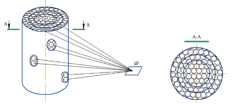
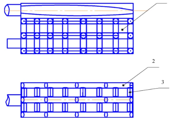
Combustion products fill free space of a pit from the bottom to the upper ingots surface. Combustion products are modeled by three tiers of elemental radiative cylinders (Figure 4).
Let us determine the power, generated in a unit length (height) of cylinder:
1
1
, cp cp n
c Р Р
l
=
∑
(13)where lc is the length of a cylinder; n is the quantity of cylinders, which combustion products are modeled by. The power of the j-th volume of combustion products is determined by the equation:
1
cpj cp j
Р =Р ⋅l (14)
where lj is the length of the j-th cylinder, modeling the j-th volume of combustion products.
Further, by the expression (10) with the aid of the program, we determine the density of the total radiation flux from all the cylinders of the combustion products to the i-th area. According to the incident obtained and own heat fluxes of elementary areas such as resultant, effective, absorbed heat flows can be calculated.
3.3. Results of Calculations of Heat Transfer in a Torch Furnace
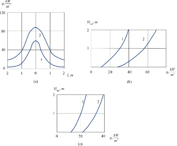
The calculation results of distribution from incident heat fluxes over the ingot surfaces along the axis О3О4 (see Figure 2) have a graphic presentation at Figure 5, Figure 6. Using the burner with β = 25˚, the zone of active combustion with temperature 1500˚С is 1.5 m distant from the frontal wall, that decreases heating of ingots, lo-cated near this wall.
Integral heat fluxes on the upper ingot surfaces are as follows (Curve 4 at Figure 5): I row is 35 kW/m2; VII row is 45 kW/m2; III-V rows are 90 - 95 kW/m2. The maximal heat fluxes fall on the upper surface of ingots, si-tuated in the middle of the heating pit. Here are the highest temperatures and the maximum heating rate of ingots. Because of the non-uniform distribution of power along the torch length, it is observed non-uniform distribution of its radiation flux along the ingot surfaces over furnace length (Curve 1 at Figure 5): I, II rows are 5 - 10 kW/m2, III-V are 20 - 30 kW/m2, VI, VII—are 15 - 20 kW/m2.
[image:7.595.174.448.504.696.2]The radiation flux densities from the cover exceed 1.5 - 2 times the radiation fluxes density from torch and non-uniformly distributed along the upper ingots surface (Curve 2 at Figure 5). The maximal density of
Figure 4. Modeling combustion products by a set of radiating cylinders (1) ingots; (2-3) lengthwise and transverse radiative cylinders.
1
2
Figure 5. Graphs of distribution of heat fluxes along the upper ingot surface with the use of burner with β = 25˚: (1-4) distribution of heat fluxes from torch, cover, respectively, from torch and cover in total, integral, calculated with the use of formula (4).
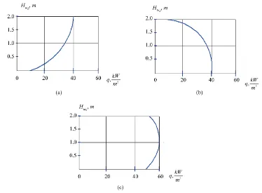
Figure 6.Graphs of distribution of heat fluxes in the neighbourhood of point О2 (а), the total integral
along the height of lateral ingot surface in the direction of the walls (b) and the axis О1О2 (c): а: (1)
from torch; (2) calculated by formula (4); b: (1) along the height of I, II, VI rows; (2) along the ingots
of III-V, VII rows; c: (1) along the ingots of I, II, VI, VII rows; (2) along the ingots of III-V rows.
[image:8.595.134.496.337.637.2]the heat flow is uniformly distributed along the upper surface of ingots and increases the total integrated radia-tion fluxes from the torch and cover by 16.2 kW/m2 (Curves 3 and 4 at Figure 5). In calculating the local view factors of radiation from surfaces to the i-th area were determined by [3], with the calculation accuracy is as high, as larger number of rectangles divide the emitting surface.
The radiation flux densities, incident on the i-th area, caused by radiation reflection of torch from the walls, cover qinr t. along with radiation reflection of surfaces from the cover, walls qinr s. due to high medium absor-bance reach 1% - 3% of the total heat flux densities from torch and cover and can’t be considered in calculations. The results of calculations by the developed procedure and expression (4) have confirmed the assumption of a prevalence of refractory lining radiation in processes of ingots heating in torch furnaces. The horizontal surface of heating along the length of the furnace from refractory lining of the cover, walls is accounts for 50% to 60% (Figure 5) of a total integrated heating flux (4). Torch accounts for 15% to 20% of a total heating flux. The heating flux from products of combustion at superposition with the heating fluxes of a torch, cover, walls, re-flected from surfaces accounts for 6 to 15% of a total heating flux along the length of heating surface.
Thus, the modern method for calculating heat transfer in torch furnaces, based on the laws for radiation from gas volumes allows to establish both qualitative and quantitative heat transfer pattern in furnaces and determine a contribution of individual components of heat sources to ingot heating in furnaces.
The main sources of heat in furnaces are torches, which heat the refractory lining of walls, cover, ingots. The refractory lining takes part in further heat transfer and heating ingots, heat fluxes equalizing on the heating sur-face. The heat of the torch fills energy loss of the lining through refractories to the furnace surroundings and lining radiant energy on ingots.
The results from calculation of heat fluxes distribution on the ingot surfaces are in good agreement with ex-ploitation practice of heating pits. To eliminate the lag of ingots heating, located near the burner wall, the burner was improved, the expansion angle of a torch was increased, that allows to decrease the non-uniformity of heat fluxes and temperatures along the length of the working space of a pit [2]. A similar result was obtained in the calculation by the abovementioned method.
The maximum density of integrated heat flux on the lining surfaces is at the O2 point of intersection of flame and burner axis with the rear wall and accounts for 90 kW/m2 (Figure 6(a)). Here mentions the maximum den-sity of the incident torch radiation flux on the heating surfaces of 60 kW/m2, which is 2 times greater than the maximum flux density of the torch on the upper horizontal surface of ingots.
The distribution of heat fluxes along the height of lateral surface of ingots Нing, faced the wall surface, is cha-racterized by significant non-uniformity (Figure 6(b)). The radiation from torch does not virtually fall on this surface and it is heated by wall radiation, combustion products and convective heat flow. The upper part of the lateral surface of ingots of III-V, VII rows has integral heat fluxes of more than 60 kW/m2, the bottom has of less than 35 kW/m2. Radiation fluxes from the surface to the i-th elementary area achieve their maximum value when it is in parallel with the surface and opposite the center of surface symmetry (Figure 5). Opposite the cen-ter of symmetry of the lacen-teral surfaces of the walls there are III-V ingot rows, the row VII is located opposite the center of the back wall of the symmetry and opposite the periphery of the lateral walls, thereby the height side ingot surface facing the back wall, created by the same distribution of heat flows, both the lateral surface of in-got III-V series (curve 2 in Figure 6(b)). The curve 1 describes the distribution of heat fluxes along the ingot height of II, VI rows at the periphery, and I row, due to the fact, that half of the front wall lining is derived from heat transfer by channels for removing flue gases and a porthole burner and does not radiate on the lateral sur-face of I row of ingots.
Figure 6 shows graphs of heat flux distribution along the height of lateral surface of ingots, faced the symme-try axis of the furnace. The surface is mainly heated by radiation from cover, combustion products and convec-tive heat flow on it. Despite the fact, that the lateral surface of ingots, faced the symmetry axis of the furnace, is under a torch, its radiation on this surface does not exceed 10% of the integral heat flux, calculated from the formula (4).
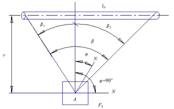
Figure 7 shows the geometric constructions for calculating radiation flux density, incident from torch of lls length on the i-th elementary area of Fk surface, situated at a distance r from the axis of the torch.
The formula for calculating has the form [2]:
(
)
(
)
{
2 2}
1 2 1 2
2 е
cos sin cos sin sin sin ,
2π kl t int ls P q
rl φ β β β β φ β β
−
Figure 7. Scheme for calculating radiation flux density of a torch on the calculation area.
where β1, β2 are the angles between the normal to the torch axis, drawn from A of the area and the ray, issued from A and passing through the left and the right cylinder bases, that the torch is modeled by; β = β1 + β2; φ is the angle between the normal to element area, drawn to A and the normal to the torch axis.
As is seen from Figure 7 and Equation (15), the maximal heat flux incident on the area from a torch, situated in parallel with the torch axis (with φ = 0, cosφ = 1, sinφ = 0) opposite the mid-length of a torch, provided that the power is uniformly distributed along its length. As the angle φ increases, the heat flux density incident on the calculated area from the torch decreases and when φ = 90˚ becomes equal to zero, that occurs at the bottom of lateral ingots surface, faced the symmetry axis of the furnace.
Significant non-uniformity of ingots heating along their height has revealed as a result of temperature mea-surements at different points of the working space of the pit and ingots heated (Figure 8). The top ingots is heated faster. At the beginning of heating, the temperature difference between the top and bottom ingots reaches 300˚C. The temperature difference decreases as the setting is heated and after 25% time of heating the ingots to a predetermined temperature it reaches 100˚C - 150˚C and remains so throughout the heating [14].
As follows from Figure 6, Figure 8, the highest heat fluxes, obtained by calculation correspond to the maxi-mum measured temperature, which confirms the adequacy of the mathematical model for calculating heat trans-fer the real heat transtrans-fer processes, occurring in the heating pit.
The use of the proposed method for calculating heat transfer in heating pits enabled us to explain non-uniform distribution of temperatures along the length of the working space, non-uniformity of heating each ingot along the height, unequal heating rate of ingots, situated in different locations of the workspace. The non-uniform dis-tribution of heat fluxes and temperatures, non-uniform heating of ingots make us bear all the setting overtime, reduce productivity, increase fuel rate. After calculation and analysis of heat flux distribution along the length and height of the furnace, it is possible to take action to equalize the heat flows along the surface of ingots. Such action includes the cyclical heating of ingots by torch with two expansion angles, the expansion angle is 19˚ - 21˚ in the first half of the cycle, and 44˚ - 46˚ is in thesecond, the cycle time is 1 - 2 minutes, expansion time for each one of the angles accounts for 0.5 - 1 min [15]. Multicyclic heating mode with two predetermined expan-sion angles of a torch allows to increase the uniformity of ingot heating, pit capacity and reduce the specific consumption of fuel for heating.
To align the ingots heating rate, nozzle gas reciprocating burner is also used [14]. The direction of the torch changes continuously by swinging the nozzle vertically, the temperature distribution along the length of the pit workspace becomes more uniform. The temperature difference between the top and bottom ingots decreases from 100˚C - 150˚C to 60˚C - 80˚C. The metal therewith is heated up faster without increasing fuel consumption. To equalize heat fluxes and temperatures, other various ways of influencing the fuel torch are used [2].
3.4. New Design of a Torch Furnace
It is offered the design of a new recuperative heating pit, providing uniformity for heating the metal ingots, for
lls
β1 β2
β
r φ
N
N φ=90˚
A
Figure 8.Temperature variation along the ingots height at a distance of 80 mm from surface in heating [14].
which purpose the design with two torches is applied (Figure 9). It is proposed to develop a new design of re-generative soaking pit, whose aim is to provide a metal ingot heating uniformity for which applies design with two torches (Figure 9). The pit comprises an extra burner, located in the lower part on the rear wall above the bottom 0.25 - 0.30 off wall height from it, two openings at the bottom for supplying the air and making a diffuse torch.
The availability of the burner on the back wall above the bottom 0.25 - 0.30 off wall height from the bottom, two openings for supplying the air to make a torch in the lower part a chamber, which is shared with the torch of the upper part of a chamber camera, provide uniform ingots heating along the height, this will lead to decrease in time of ingots heating, increase in productivity, decrease in fuel consumption.
The upper torch 9 heats the upper part of ingots and the lower torch 11 heats the lower part of ingots 8, as a result, total heat fluxes incident on ingots surface 8 from torches 9 and 11 are leveled off and the uniformity of ingots heating along the height increase (Figure 10).
Uniform distribution of heat fluxes and temperature at the height of 8 ingots significantly reduces the time of their heating to the desired temperature, increases the capacity of regenerative pit, reduces fuel consumption [16].
4. Research on the Effect of Torch Parameters on Heat Transfer in a Heating Pit
4.1. Results of Calculation of Heating Fluxes Distribution along the Heating Surfaces
under Changes of Torch Length
The effect of the position and size of a torch on thermal destruction and useful life of the burners, the distribu-tion of heat fluxes on the heating surfaces have not been clarified for a considerable time. Let us calculate the distribution of heat fluxes from the torch on the burner throat surface under change of torch length. Figure 5 shows the calculated data of heat fluxes distribution on the horizontal heating surface in the recuperative heating pit with one top burner when the torch length lt is equal to the length of the heating surface and the length of the furnace lfur. Let us consider the changes of heat fluxes from the torch on the horizontal heating surface and ver-tical surface of a burner throat under changes of torch length. Figure 11 presents a sectional cutting of heating pit with the upper torch, bounded by a cover and horizontal heating surface at top and bottom, respectively.
Torch length is changed by changing the expansion angle of the torch (Figure 11), the torch temperature in-creases with decreasing torch length at its constant power.
The geometrical dimensions of the torch determine the distribution of the heat fluxes from torch on all the heating surfaces, including the burner throat, this may be seen by making the following calculations.
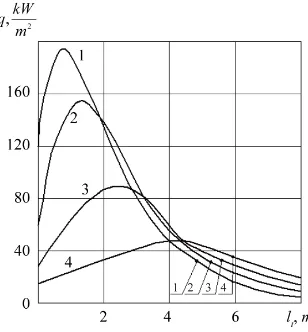
We calculate the distribution of heat fluxes from the torch along the length of the horizontal heating surface and the length of the furnace when changing the length of the torch and its constant power of 4.2 MW. The cal-culation of integral radiation flux from torch incident on any i-th calculated area was carried out by the formula (5). The calculation results are presented in Figure 12.
Figure 9. Schematic design of recuperative heating pit with two torches. (1) chamber, (2) frontal wall, (3) lateral wall, (4) rear wall, (5) shuffle cover, (6) bottom, (7) burner, (8) ingots, (9) upper torch, (10) burner, (11) lower torch, (12) openings for supplying the air.
Figure 10. Distribution of the average heating fluxes along the ingots height when the upper burner operates (a), the lower burner operates (b), the lower burner and the upper burner operate together (c).
at the back wall. The maximal non-uniformity of heat fluxes density distribution over the horizontal heating surface is seen at lt = 2 m: near the front wall the heat fluxes density on the horizontal surface is 195 kW/m2, at the same distance from the back wall the heat fluxes density is 5 kW/m2. Thus, the distribution of heat fluxes on heating surfaces from torch depends on the geometric dimensions of the torch.
4.2. Results of Calculations of Heat Fluxes Distribution from Torch on Torch Throat
Surface
Figure 13 shows the results of calculations from heat fluxes density distribution incident on the vertical surface of the burner throat from the torch throughout the height hа= 1 m from the burner axis. The maximal value qmax
3 9
5 1
8 7
2
6
12
11
[image:12.595.126.500.297.572.2](a)
(b)
(c)
[image:13.595.135.511.79.607.2](d)
Figure 11. Torch length change in heating furnace, l = 8 m, β = 25˚ (а), lt = 5 m, β = 32˚ (b), lt =
3 m, β = 56˚ (c), lt = 2 m, β = 105˚ (d): (1) the frontal wall and the burner throat; (2) burner; (3)
furnace cover; (4) torch; (5) isotherms; (6) horizontal heating surface of ingots.
is the symmetry axis of the burner and throat and the minimal value is at the periphery of the throat. The density changes depending on the torch length as follows: lt = 8 m, qmax = 150 kW/m2; lt= 5 m, qmax = 300 kW/m2; lt = 3 m, qmax = 600 kW/m2; lt= 2 m, qmax = 1050 kW/m2.
Thus, the more the length of the torch, the less the heat fluxes density incident on the burner and the throat from torch and vice versa, the less the length of the torch at its constant power, the more the thermal load on the burner and the throat as along their axis so at the periphery. The calculation results are confirmed by the practice
1300
С1500
С1400
С1300
С1 2
3 4 5 6
1300
С1500
С1400
С1300
С1 2
3 4 5 6
˚C
˚C
˚C
˚C
1300
С1500
С 1400
С1500
С 1300
С1500
С 1400
С1500
С ˚C˚C
˚C
˚C
1400
С1500
С1400
С1300
С 1600
С1700
С 1400
С1500
С1400
С1300
С 1600
С1700
С˚C ˚C
˚C
Figure 12. Graphs of distribution of heating fluxes from torch to the horizontal heating surface: 1—lt = 2 m; 2—lt = 3 m; 3—lt = 5 m; 4—
lt= 8 m.
Figure 13. Graphs of heat fluxes distribution on the throat surface from torch (designations are the same as at Figure 12).
of burners operation in steam boiler boxes [17]. When the torch length lt= 0.5 m, the useful life of gas nozzle burners equaled 0.5 - 1.0 year, NOx formation from steam boiler is 350 - 450 mg/m3.
In order to analyze the possibility of increasing the useful life of the burners, empirical studies were used, in which the length of the torch was repeatedly increased. By increasing it to 2.5 m, the useful life of the burners is extended to 2 - 4 years, the output of nitrogen oxides decreased by more than 40% up to 250 - 350 mg/m3. Cal-culations show (Figure 13), that as the torch length increases 4 times—from 2 to 8 m, the maximum heat flux density to the burner nozzle decreases 7 times from 1050 to 150 kW/m2, which helps prolonging the useful life of the burner. Output reduction of nitrogen oxides under increasing the length of the torch is due to decrease in the maximum temperature from 1700˚C to 1500˚C.
Thus, from the results of calculation of radiation fluxes density distribution from torch along the horizontal surface of heating and vertical throat surface (Figure 12, Figure 13) follows, that the maximal radiation fluxes from torch are on the vertical surface on the torch and burner axes, with they exceed the radiation flux density on the horizontal heating surface 4 - 5 times at any length of the torch.
The changes of torch radiation ratio on the central area of 0.5 × 0.5 m throat under changes of torch length were calculated. The proportion of the torch radiation from all its radiation on the throat area in the surroundings is characterized by the average view factor of radiation on the area φt. Figure 14 shows the relationship between
[image:14.595.201.436.295.479.2]Figure 14. Change of the average view factor of radiation on the burner throat.
throat area: when lt = 2 m, φt = 0.2, when lt= 8 m, φt = 0.08. The results of calculation from the average angular coefficients of radiation on throat and burner areas and practice of burners operation the burners are in harmo-nious accordance with each other: the shorter the torch, the greater the proportion of the radiation incident on throat and burner and the less useful life of the burner, and vice versa, the longer the torch, the less proportion it radiates on throat and burner and the longer useful life of the burner.
5. Conclusions
Thus, the laws of radiation from surfaces (laws of radiation form black body) should be used when solid fuel is fired and also for calculation heat radiation from refractory lining (analysis of radiative heat transfer in furnaces). But the use of these laws is unacceptable in calculating heat transfer in torch furnaces during combustion of gas, liquid, and pulverized fuel. This case requires to calculate not surface, but volume radiation from torch on heat-ing areas and use the laws of radiation from gas volumes, Makarov’s laws. The calculations made on their basis showed the short life of the burner under short torch and increase in its useful life under increase in torch length. A comparison of calculation and experimental data shows that the laws of radiation from gas volumes and the method of calculation heat transfer in torch furnaces, fire boxes, combustion chambers, developed on their basis, are in harmonious accordance with the practice of operation of these units.
The calculation results are in good agreement with the results of measurements of temperatures in the work-ing space and on work-ingots surfaces. Maximum heat fluxes determined by calculation correspond to the maximum temperatures, obtained from measurements, and vice versa, minimum heat fluxes found by calculation corres-pond to the minimum temperatures obtained from measurements, which confirm the adequacy of the developed mathematical model to the real heat exchange processes in the working space of the furnace.
Increasing the density of heat fluxes to the heating surface can be achieved by increasing the power of the torch.
For the first time the method appeared for calculating the volume radiation from the torch, which takes into account every second radiation of all its particles (depending on the gas volume of the torch and fuel consump-tion) and allows calculating the average length of the beam paths of all the photons, the radiation flux densities incident on calculated heating surfaces from gas volumes. The laws of gas radiation, the laws of Makarov, and the method for calculating heat transfer, developed on their basis, make it possible to explain the reasons for non-uniform heating of items in torch furnaces, define rational position and dimensions of the torch in them, and create innovative energy-saving torch furnaces [18]-[21].
References
[1] Makarov, A.N. and Svenchanskii, A.D. (1992) Optimal Operating Conditions of Arc Steel Melting Furnaces. Ener-goatomizdat, Moscow, 96 p. (In Russian)
[image:15.595.230.396.84.267.2][3] Blokh, A.G., Zhuravlev, Yu.A. and Ryzhkov, L.N. (1991) Radiant Heat Transfer: A Handbook. Energoatomizdat, Moscow, 432 p. (In Russian)
[4] Zigel, R. and Howell, J. (1975) Radiative Heat Exchange. М.: Mir, 934 p.
[5] Sparrow, E.М. and Cess, R.D. (1971) Radiative Heat Exchange. L.: Energia, 294 p. [6] Chandrasekar, S. (1993) Radiation Transfer. М.: IL, 431 p.
[7] Spoulding, D.B. (1968) Combustion, Flame and Gas Blasts. М.: Mir, 592 p.
[8] Makarov, A.N. (2012) A Regular Correlation between the Parameters Characterizing Radiation from Isothermal Coaxial Cylindrical Gas Layers Generated during Flame Combustion of Fuel and Electric Arc Burning in Metal Va-pors at Atmospheric Pressure (Makarov’s Regularities), Diploma No. 47. In: Pototskii, V.V., Ed., Scientific Disclo-sures: A Collection of Brief Descriptions of Scientific Disclosures, Scientific Ideas, and Scientific Hypotheses, RAEN, Moscow, 33-37. (In Russian)
[9] Makarov, A.N. (2014) Theory of Radiative Heat Exchange in Furnaces, Fire Boxes, Combustion Chambers Is Reple-nished by Four New Laws. Science Discovery, 2, 34-42. http://dx.doi.org/10.11648/j.sd.20140202.12
[10] Makarov, A.N. (2014) Regularities Pertinent to Heat Transfer between Torch Gas Layers and Steam Boiler Firebox Waterwalls. Part I. Geometrical and Physical Torch Model as a Source of Heat Radiation. Thermal Engineering, 61, 642-648. http://dx.doi.org/10.1134/S004060151406007X
[11] Makarov, A.N. (2014) Regularities Pertinent to Heat Transfer between Torch Gas Layers and Steam Boiler Firebox Waterwalls. Part II. Gas Layer Radiation Laws and the Procedure for Calculating Heat Transfer in Furnaces, Fire Box-es, and Combustion Chambers Developed on the Basis of These Laws. Thermal Engineering, 61, 717-723.
http://dx.doi.org/10.1134/S0040601514100073
[12] Makarov, A.N. (2014) Regularities Pertinent to Heat Transfer between Torch Gas Layers and Steam Boiler Firebox Waterwalls. Part III. Examples of Heat Transfer Calculation in Torch Furnaces and Steam Boiler Fireboxes. Thermal Engineering, 61, 814-821. http://dx.doi.org/10.1134/S0040601514110056
[13] Makarov, A.N. (2015) Laws of Heat Radiation from Surfaces and Gas Volumes. World Journal of Engineering and Technology, 3, 260-270. http://dx.doi.org/10.4236/wjet.2015.34027
[14] Krivandin, V.A. and Egorov, A.V. (1989) Thermal Work and Designs of Ferrous Metallurgy Furnaces: A Handbook. Metallurgiya, Moscow. (In Russian)
[15] Makarov, A.N. and Dunaev, A.Yu. (2006) The Way of Heating Ingots in a Heating Well. RF Patent No. 2274663. [16] Makarov, A.N., Galicheva, M.K. and Rybakova, V.V. (2015) Recuperative Heating Pit. RF Patent No. 2521772. [17] Osincev, K.V. (2009) The Way for Decreasing Heat Flux on Throat Burners. Electricheskie Stancii, 11, 15-21. [18] Makarov, A.N. and Shevchenko, M.N. (2010) Furnace for Combustion Gaseous Masout Fuel. RF Patent 2400668. [19] Makarov, A.N. and Shcheglov, A.G. (2012) Regenerative Soaking Pit. RF Patent 2457262.
[20] Makarov, A.N., Kruglov, Е.V. and Rybakova, V.V. (2014) Direct-Current Arc Steel Melting Furnace. RF Patent 2516896.
Submit or recommend next manuscript to SCIRP and we will provide best service for you: Accepting pre-submission inquiries through Email, Facebook, LinkedIn, Twitter, etc.
A wide selection of journals (inclusive of 9 subjects, more than 200 journals) Providing 24-hour high-quality service
User-friendly online submission system Fair and swift peer-review system
Efficient typesetting and proofreading procedure
Display of the result of downloads and visits, as well as the number of cited articles Maximum dissemination of your research work
![Figure 8. Temperature variation along the ingots height at a distance of 80 mm from surface in heating [14]](https://thumb-us.123doks.com/thumbv2/123dok_us/7871212.738570/11.595.229.403.85.208/figure-temperature-variation-ingots-height-distance-surface-heating.webp)