A Review of Loading & Unloading on Intermidate Casting for Effective
Support in Drilling Machine
A. Kalaiyarasan
1B. Brindhavanan
2S. Sasidharan
3M. Arulmani
4Dr. S. Sundaram
51,2,3,4
Assistant Professor
5Professor & Head of Departent
1,2,3,4,5Department of Mechanical Engineering
1,2,3,4,5
Muthayammal Engineering College, Rasipuram, Tamil Nadu, India
Abstract— Casing design is one of the most important aspects of drilling Engineering. It is a way of analysing stress for the wellbore. This paper aimed at providing a new method for optimal design of intermediate casing that can withstand a variety of external, internal, thermal, and self-weight loading, while at the same time being subjected to wear and corrosion for optimal well delivery. The methodology employed involves the assessment of pore pressure and fracture pressures for optimal casing seats selection, designing for burst, collapse and tension while considering other external loads. From the simulation carried out for the intermediate section of the well, it was only casing J9 for the case study well that satisfied the load conditions in terms of burst and collapse pressures. This study showed that casings should never be designed to their yield strength or tensile strength limits; instead a design factor should be used to estimate the strength of the casing so that the casing would not be loaded beyond its capacity.
Key words: Burst Pressure Design, Casing Setting Depth, Collapse Pressure Design, Intermediate Casing, Tensile Loading Design
I. INTRODUCTION
Casing design is simply a stress analysis procedure of the wellbore [1]. It predominantly has to do with selecting the appropriate casing size, appropriate setting depth, detection of the operational cases that will lead to collapse, burst or axial loading on the casing, calculating the magnitude of the loads and lastly for selecting the correct weight and grade of casings[2]. Ideally the drilling engineers would prefer to drill from surface to the target depth without setting casing at all because of time and cost, but in reality, many casing strings would be required to get to TD. The geology and the anticipated pore pressure in that locality go a long way in influencing the sizes and the setting depths of casings. [2].
The earth does not allow vacuum in nature. It is therefore important to fortify the well of an open hole drilled to lift oil and gas to the surface in order to avoid numerous hole problems such as caving-in, collapse, fallout, erosion etc. The fortification of the well bore is done using steel pipe, known as casing lowered to the drilled hole during drilling operation. Casings are rated and graded according to known standard. It is very important for the engineer to always bear in mind the risk involved in designing a specific hole section with the wrong casing weight and grade. From experience, we can deduce that the maximum number of different casing grades most rigs can comfortably handle is three. [3].
The challenge in getting a proper casing design is a challenge that needs to be handled with great importance because; a poor casing design leads to poor well performance; the cost of casing (usually 20-40% of the total cost of a well) contributes immensely to the overall cost of a well; poor
casing design places the well and personnel at risk as casing failure could be catastrophic; low reservoir productivity and poor well delivery have been linked in several occasions to poor casing design. The main cause of casing failure from collapse pressure has been suspected to be the fluid in the annulus between two casings [4], [5]. Southon in [5] discussed the modes of casing failure in geothermal wells and highlighted the importance of a careful and thorough implementation of the well design. He also stated that pre-tension loads need to be determined to avoid compression yielding when using buttress threaded couplings. Leaver in [6] discussed the helical buckling and Euler buckling. He highlighted how analyses were done. Euler buckling was also addressed by Richard and Schuler [7] where buckling models were produced. Kane [8] evaluated corrosion problems involving in-service failures of geothermal well production casings where high thermally induced tensile stress in the presence of hydrogen sulfide leads to sulfide stress cracking. A two dimensional (2-D) finite element model of the cross section of a double cased geothermal well was created for representing the behavior of the cement/sealant by Philippacopoulos and Berndt in [9]. It was shown that the compressive strength alone was not adequate in the design of geothermal well
A. Casing Design Process
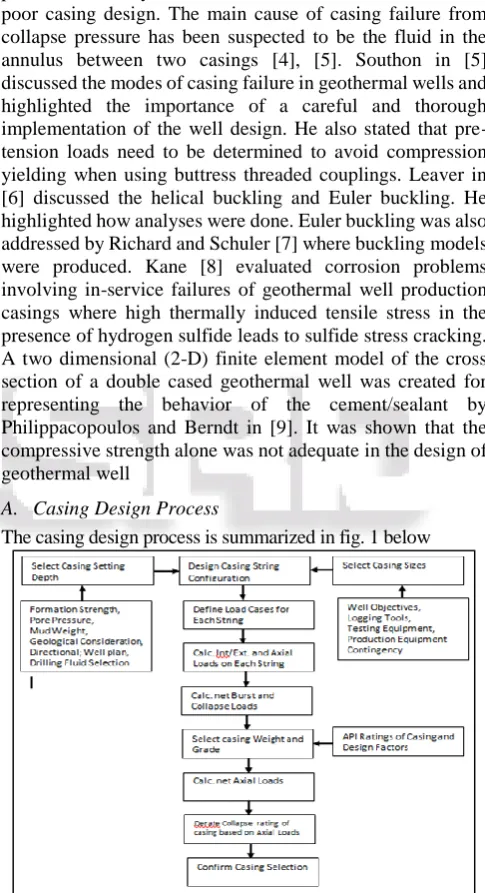
[image:1.595.306.549.192.639.2]The casing design process is summarized in fig. 1 below
Fig. 1: A Typical Casing Design Process
B. Design Factors (DF) Application
The API bulletin clearly specifies tubing and casing minimum performance properties and they are used to ascertain if selected casing falls within the design factor. Normally the design factor is used in burst, collapse and tension design.
1.3. Burst Model
In general, Burst Pressure σp is given by:
1) Burst Model for Each Individual Casing String
At the top of the hole, the external pressure is zero and the internal pressure must be supported entirely by the casing body.
Therefore, burst pressure is highest at the top and lowest at the casing shoe where internal pressures are resisted by the external pressure originating from fluids on the outer part of the string.
a) Intermediate Casing
The equations for the internal and external pressures will be highlighted below
(1) Internal Pressure In surface wellheads;
BP@ wellhead= 60
100∗ (FP@ shoe− GCP@ wellhead) (2) OR
BP@ surface= 0.6( Internal Pressure − External Pressure) (3) Since the external Pressure @ the surface =0;
Then
Sureface Burst Pressure = σi(surface) Where
σi(surface)= Pf− G ∗ TD (4) In subsea wellheads;
BP@ wellhead= [ 60
100∗ (FP@ shoe− GCP@ wellhead)] −σseawater (5) OR
BP@ wellhead= σi(surface)− σseawater (6) Where;
σi(surface)= (Pf− G ∗ TD) = Burst Pressure @ the surface
Note that external pressure at the surface = 0 Pf = Formation Pore pressure @ casing seat (Psi)
The burst pressure limit at the bottom of the hole is equivalent to fracture gradient that was predicted for the hole section below the casing shoe.
Bottom Hole Burst Pressure = (Fracture Gradient) predicted @ shoe
Or
σburst @ shoe= σi(casing shoe)−σback up (7) σback up= 0.465 ∗ CSD (8) Where;
σi(casing shoe)= Pf− {G ∗ (TD − CSD) } (9)
σburst @shoe= [Pf− {G ∗ (TD − CSD)}] − ( 0.465 ∗ CSD) (10)
(2) External Pressure
This pressure is equivalent to the formation pressure. If a subsea wellhead is installed, then the seawater hydrostatic pressure is to be taken into consideration.
σnetburst =(σ internal – σ external) @ each depth (11)
C. Collapse Model
The following simplified procedure was used for collapse design; the casing was taken to be empty due to losses at the casing setting depth; the internal casing pressure is assumed to be zero (0); the external pressure is mainly due to the drilling fluid lastly it was assumed that there was cement on the outer part of the casing.
Collapse pressure = 0.052 * ρm* CSD (12)
1) Intermediate Casing
The equations for the internal and external pressures will be highlighted below
a) Internal Pressure
Complete evacuation in intermediate casing is virtually impossible. Casing collapse is most likely to occur where there is mud losses as we drill into a new hole section using the maximum allowed mud density. This will bring about a drastic fall in the level of mud inside the casing. H will be taken as the height of the new low level of mud in the casing.
(Hloss− H) ∗ρm= Hloss∗ Gp (13) Where;
H = Hloss∗
(ρm − Gp)
ρm (14) If Gp = 1.03 (Kg / cm2 /10m)
Then
H = Hloss∗
(ρm− 1.03)
ρm (15)
b) External Pressure At Surface:
Collapse pressure = 0 At depth (CSD-L)
Collapse Pressure@ CDS_−L= (0.052 ∗ CDS ∗ρm) (16) At depth CSD
Collapse Pressure@ CDS_= (0.052 ∗ CDS ∗ρm) − (0.052 ∗
L ∗ρm−next ) (17)
ρm−next = mud weight in which casing was run in.
L = CSD - h = Length of mud column inside the casing (ft) h = depth of top of mud inside casing after loss circulation
h = (ρml−next−ρf
ρml−next ) ∗ Dlz (18)
Hence
Net Collapse Pressure
σCollapse= σexternal presure−σinternal pressure (19) Tables 1 and 2 show the recommended design factors for the different design criteria.
Design Criteria Recommended Design Factors
Collapse 1.0
Burst 1.1
Tension 1.6-1.8
Compression 1.0
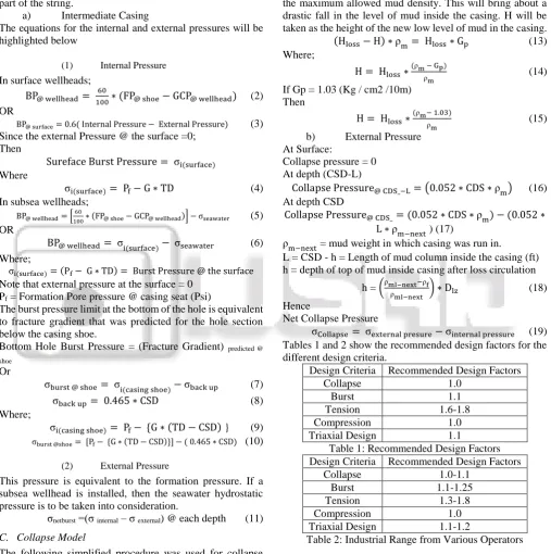
[image:2.595.296.545.141.667.2]Triaxial Design 1.1
Table 1: Recommended Design Factors Design Criteria Recommended Design Factors
Collapse 1.0-1.1
Burst 1.1-1.25
Tension 1.3-1.8
Compression 1.0
Triaxial Design 1.1-1.2
Table 2: Industrial Range from Various Operators
D. Tension Design Model
When designing for tension, information on the casing grade and weight is very essential. Some forces must be considered when tension is being discussed. They are: the buoyancy force, the buoyant weight of casing, the bending force and the shock load.
1) Load Cases
[image:2.595.46.554.151.662.2]& static conditions. These load cases are sometimes described as Installation Load cases.
a) Load Case I: Running Conditions
This is simply a case of running the casing inside the drilled hole section before the cement job.
𝑇𝑜𝑡𝑎𝑙 𝑡𝑒𝑛𝑠𝑖𝑙𝑒 𝑓𝑜𝑟𝑐𝑒 = 𝑏𝑢𝑜𝑦𝑎𝑛𝑡 𝑤𝑒𝑖𝑔ℎ𝑡 + 𝑏𝑒𝑛𝑑𝑖𝑛𝑔 𝑓𝑜𝑟𝑐𝑒 + 𝑠ℎ𝑜𝑐𝑘 𝑙𝑜𝑎𝑑 (20)
b) Load Case II: Pressure Testing Conditions This is simply when the casing is sent down to the target depth. Cement has just being pumped, hence not dry.
𝑇𝑜𝑡𝑎𝑙 𝑡𝑒𝑛𝑠𝑖𝑙𝑒 𝑓𝑜𝑟𝑐𝑒 = 𝑏𝑒𝑛𝑑𝑖𝑛𝑔 𝑓𝑜𝑟𝑐𝑒 + 𝑏𝑢𝑜𝑦𝑎𝑛𝑡 𝑤𝑒𝑖𝑔ℎ𝑡 + 𝑝𝑟𝑒𝑠𝑠𝑢𝑟𝑒 𝑡𝑒𝑠𝑡𝑖𝑛𝑔 𝑓𝑜𝑟𝑐𝑒 (21)
c) Load Case III: Static Conditions
In this case, the casing has already been sent down, cement is set and the wellhead mounted.
𝑇𝑜𝑡𝑎𝑙 𝑡𝑒𝑛𝑠𝑖𝑙𝑒 𝑓𝑜𝑟𝑐𝑒 = 𝑏𝑒𝑛𝑑𝑖𝑛𝑔 𝑓𝑜𝑟𝑐𝑒 + 𝑏𝑢𝑜𝑦𝑎𝑛𝑡 𝑤𝑒𝑖𝑔ℎ𝑡 + 𝑚𝑖𝑠𝑐𝑒𝑙𝑙𝑎𝑛𝑒𝑜𝑢𝑠 𝑓𝑜𝑟𝑐𝑒𝑠 (22) Again, it is imperative for the design factor in tension during pressure testing to be greater than 1.6, i.e.
DF − T = YieldStrength
TotalTensiltforceduringPressureTesting (23)
E. Service Loads during Drilling & Production Operation
Once the casing is landed and cemented, it will be subjected to additional forces if drilling is continued beyond this casing or if this casing is used as a production casing. These service loads represent extra set of load cases which must be checked before the casing is selected. To calculate the tensile load on the casing, the base load must first be calculated:
F base load = Air weight – Buoyancy force + bending force + Pressure testing force + landing force (if applied) (24) The additional forces that must be added include ballooning force, compression load, biaxial stress and temperature force.
F. Casing Wear
1) Volumetric Casing Wear
During string rotation, we can estimate the volume of casing wear by using equation 25 below:
V = Input Energy
Specific Energy (25)
V =60πFLDNS
P (26) Note:
Accepted limit of casing wear is < or = 7%.
II. RESULTS & DISCUSSION
A. Formation Pore Pressure & Fracture Gradient Data Sources
Formation pore pressure and formation fracture pressure data were gathered from offset wells and well logs in the Niger Delta as shown in Table 3. Figure 2 shows the profile of the data shown in table 3.Well summary is shown in table 4
Depth(ft) Pore Pressure (Emw,ppg)
Fracture pressure (Emw,ppg)
1000 5.8 9.3
2000 5.8 9.3
3000 5.8 9.8
4000 5.9 10.2
5000 6.9 10.8
6000 7.4 11.8
7000 8.8 12.4
8000 10.6 12.9
9000 11.4 13.6
10000 12.2 14.3
11000 13 14.5
12000 13.3 14.8
13000 13.6 14.9
14000 13.6 15.2
[image:3.595.305.551.60.311.2]Table 3: XXX Formation Pressure data from the Niger Delta
Fig. 2: formation Pore Pressure & Fracture Pressure Profile
[image:3.595.303.553.345.569.2]B. Geological Overview and the Well Brief
Table 4 shows the well summary. Well Name and
Location
XXX, OML – XXX, Niger of Nigeria Nigeria
Surface Coordinate:
Nigeria Fed (XXX Belt) Coordinates XXX, YYYmN;
ZZZmE Proposed Bottom
Coordinate XXXmN; YYYmE
Ground Level 120Feet (XXmeters) Drilling Floor
Elevation(DFE) 510 Feet (XXXmeters)
Depth 12,294ft MD (3617.8m); 11,500ft TVD (3617.8m) Expected Spud Date March, 2014
Well Type Deviated
Primary Objective Develop X1, Y1, Y2and Y4 sand for Gas
Secondary Objective Appraise G5 and others Table 4: Well Summary
Analysis of the data provided in Tables 3 and 4 and the subsequent ones shall be presented with the aid of WRENCH software developed for this purpose.
C. Casing Setting Depth
Fig. 3: Casing Setting Depth Analysis
D. Casing Burst Design Criteria
Figure 4 and Table 5 shows the input parameters and calculated result for casing burst design criteria respectively. Figure 5 is the burst design chart.
Fig. 4: Graphic User Interface (GUI) for input parameters for burst design criteria.
Table 5: Calculated result for burst design criteria
Fig. 5: Burst Design Chart
E. Casing Collapse design Criteria
Figure 6 and Table 6 present the input parameters and calculated result for casing collapse design criteria respectively. Figure 7 shows the collapse design chart
Figure 6: Graphic User Interface (GUI) Input Parameters for Collapse Design Criteria
Table 6: Calculated result for Collapse design criteria
Fig. 7: Collapse Design Chart
F. Casing Tension Design Criteria
Figure 8 and Table7 present the input parameters and calculated result for casing tension design criteria respectively.
Fig. 8: Graphic User Interface (GUI) Input Parameters for Tension Design Criteria
Table 7: Calculated Result for Tension Design Criteria
G. Casing Selection
Table 8 provides the specification of the available casing while Figures to follow provides the initial selection. But before ever a load case is to be applied, we must first select the grade and weight of the casing based on the collapse and burst pressures. 2.8. Analysis of the available casing grade
Tubular Depth (ft) Size (in)
Weight
(Ib/ft) Grade Thread
Burst/Collapse (Psi)
Tensile Body/Joint (X1000Ibs)
Intermediate 0- 10,000 9-5/8 43 J5 ST&C 5434/6720 541/322
Intermediate 0- 10,000 9-5/8 42 J6 ST&C 5500/6920 425/392
Intermediate 0- 10,000 9-5/8 40 J8 ST&C 5300/9000 524/392
Intermediate 0- 10,000 9-5/8 40 J9 ST&C 5300/11320 544/390
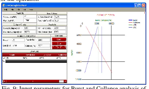
Table 8: Specification of Available Casing Fig. 9: shows that casing grade J5 only satisfied burst pressure
[image:5.595.47.289.134.278.2]but does not satisfy collapse pressure and therefore not suitable for the operation
Fig. 9: Input parameters for Burst and Collapse analysis of Casing Grade J5
[image:5.595.47.294.329.495.2]Figure 10 shows that casing grade J6 only satisfies burst pressure but does not satisfy collapse pressure and therefore not suitable for the operation.
Fig. 10: Input Parameters for Burst and Collapse Analysis of casing grade J6
[image:5.595.47.289.530.683.2]Figure 11shows that casing grade J7 only satisfied burst pressure but does not satisfy collapse pressure and therefore not suitable for the operation.
Fig. 11: Input Parameters for Burst and Collapse Analysis of Casing Grade J7
Figure 12 showed that casing grade J8 only satisfied burst pressure but does not satisfy collapse pressure and therefore not suitable for the operation.
III. CONCLUSION
The efficiency of casing design depends on the accuracy of the data acquired. A misleading data set could lead to over design or an under design. Casing should first be designed for burst and collapse and after which, tension, wear and tri-axial before other external factors may be considered. From the analysis presented in this study, it is recommended that Casing grade J9, having met both the burst and collapse pressure is recommended for the intermediate section of the case study well in the Niger Delta.
REFERENCES
[1] Eni-Agip (2013). Casing Design Manual, Ref. 119, pg 1-134
[2] Hussain, Rabia (2002). Well Engineering and Construction, Entrac Consulting, ISBN: 0954108701. [3] Björnsson, G.; Ragnars, K.;Sigfússon, S.and Karlsson,Þ
(1978). Styrkleikifóðurröra í háhitaborholum(OS JH 7805) (in Icelandic). Reykjavík: Orkustofnun.
[4] Magneschi, P.; Bagnoli, C.;Lazzarotto, A.and Ricciardulli, R. (1995). Structural Models for the Analysis of Stresses in the Casings of Geothermal Wells. Proceedings of World Geothermal Congress, Italy. [5] Southon, J.N. A. (2005).Geothermal Well Design,
Construction and Failures. Proceedings of World Geothermal Congress, Antalya, Turkey.
[6] Leaver, J.D.(1982). Failure Mode Analysis for Casing and Liners in Geothermal Production Wells. Proceedings of the 4th New Zealand geothermal workshop.
[7] Rechard, R. P.;and Schuler, K. W. (1983). Euler Buckling of Geothermal Well Casing. Albuquerque, New Mexico: Sandia National Laboratories.
[8] Kane, R. D. and Greer, J.B. (1976). Sulphide stress cracking of high-strength steels in laboratory and oil field environments. Journal of Petroleum Technology, AIME, October 1976, SPE 6144.