Virtual Machine Showdown: Stack versus Registers
by
Yunhe Shi, BSc. MSc.
Dissertation
Presented to the
University of Dublin, Trinity College
in fulfillment
of the requirements
for the Degree of
Doctor of Philosophy
University of Dublin, Trinity College
Declaration
I, the undersigned, declare that this work has not previously been submitted as an
exercise for a degree at this, or any other University, and that unless otherwise stated,
is my own work.
Yunhe Shi
Permission to Lend and/or Copy
I, the undersigned, agree that Trinity College Library may lend or copy this thesis
upon request.
Yunhe Shi
Acknowledgments
I would like to express my sincere gratitude to my supervisor, Dr David Gregg. His
encouragement, patience, understanding, guidance, and financial support ensured the
completion of this dissertation. Since English is not my native language, he has spent
a considerable time and effort to correct countless grammatical and spelling errors in
my papers and thesis . Without him, it would not have been possible for me to finish
my PhD.
I would like to thank Griffith College Dublin for half of the PhD fee sponsorship.
I would like to thank the staff of the computing faculty at Griffith College Dublin for
their kind supports. Particular gratitude to Eamonn Nolan, Tony Mullins, Kevin Hely,
and Waseem Akhtar.
I would also like to thank the members of the Computer Architecture Group who
have been great company and of great assistance through the years. Particular thanks
to Kevin Casey and Andrew Beatty from the group, with whom I have worked on many
issues relating to the Java Virtual Machine. Thanks also go to Nicholas Nash and Paul
Biggar, who spent their precious time proof-reading the draft of this dissertation.
Special thanks are also due to M. A. Ertl of the Technical University, Vienna, for
his unselfish assistance and ready availability to offer advice throughout the duration
of this project.
Finally, my greatest appreciation is reserved for my parents for their support during
Yunhe Shi
University of Dublin, Trinity College
Virtual Machine Showdown: Stack versus Registers
Publication No.
Yunhe Shi, Ph.D.
University of Dublin, Trinity College, 2007
Supervisor: Dr. David Gregg
Virtual machines (VMs) enable the distribution of programs in an
architecture-neutral format, which can easily be interpreted or compiled. The most popular VMs,
such as the Java virtual machine (JVM), use a virtual stack architecture, rather than
the register architecture that are most popular in real processors. A long-running
question in the design of VMs is whether a stack architecture or register architecture
can be implemented more efficiently with an interpreter. On the one hand, stack
architectures allow smaller VM code so less code must be fetched per VM instruction
executed. On the other hand, stack machines require more VM instructions for a
given computation, each of which requires an expensive (usually unpredictable) indirect
This dissertation extends existing work on comparing virtual stack and virtual
register architectures in three ways. Firstly, we generate very high quality register code.
The result is that our register code has 46% fewer executed VM instructions compared
to optimized JVM stack code, with the bytecode size of the register machine being
only 26% larger than that of the corresponding stack code. Secondly we present a fully
functional virtual-register implementation of the Java virtual machine (JVM), which
supports Intel, AMD64, PowerPC and Alpha processors. This register VM supports
inline-threaded, direct-threaded, token-threaded, and switch dispatch. Thirdly, we
present experimental results on a range of additional optimizations such as register
allocation and elimination of redundant heap loads. On the AMD64 architecture the
register machine using switch dispatch achieves an average speedup of 1.48 over the
corresponding stack machine. Even using the more efficient inline-threaded dispatch,
the register VM achieves a speedup of 1.15 over the equivalent stack-based VM.
The performance of VM interpreters is much affected by indirect branches and
during the course of the work on VM interpreters we identified a strong interaction
between the indirect branch predictor and the trace cache. The dissertation investigates
the related phenomenon, and shows that the interaction between the two components
results in significant improvements in indirect branch prediction. This is particularly
Contents
Acknowledgments iv
Abstract vi
List of Tables xii
List of Figures xiii
Chapter 1 Introduction 1
1.1 Motivation . . . 1
1.2 Our Thesis . . . 2
1.3 Contributions . . . 2
1.4 Collaborations . . . 4
1.5 Overview . . . 5
Chapter 2 Background 7 2.1 Introduction . . . 7
2.2 Virtual Machines . . . 7
2.2.1 High-Level Language VMs . . . 7
2.2.2 The Pascal P-Code Virtual Machine . . . 9
2.3 The Java Virtual Machine . . . 9
2.3.1 The Internal Architecture of a Java Virtual Machine . . . 10
2.3.2 Execution Engine . . . 12
2.3.3 Java Bytecode Instruction Set . . . 13
2.4 Modern Processor Architecture . . . 14
2.4.2 Pipelining . . . 16
2.4.3 Branch Prediction . . . 17
2.5 Conclusion . . . 19
Chapter 3 Literature Survey 20 3.1 Introduction . . . 20
3.2 Virtual Machine Interpreters . . . 21
3.3 Dispatch Cost Reduction Techniques . . . 23
3.3.1 switch Dispatch . . . 23
3.3.2 Token-Threaded Dispatch . . . 26
3.3.3 Direct-Threaded Dispatch . . . 27
3.3.4 Indirect-Threaded Dispatch . . . 27
3.3.5 Static Superinstructions . . . 29
3.3.6 Inline-Threaded Dispatch . . . 29
3.3.7 Context-Threaded Dispatch . . . 30
3.3.8 Vmgen Interpreter Generator . . . 32
3.3.9 Summary . . . 32
3.4 Interpreter Stack Caching . . . 32
3.5 Register Machines . . . 36
3.5.1 Stack vs. Register Instruction Sets . . . 36
3.5.2 Register-Based Virtual Machines . . . 38
3.5.3 Virtual Register Organization . . . 40
3.5.4 Java Virtual Machine Related Research . . . 41
3.6 Indirect Branch Prediction . . . 41
3.6.1 BTB with 2-bit Counters . . . 43
3.6.2 2-Level Prediction of Indirect Branches . . . 43
3.7 Trace Cache . . . 45
3.8 Conclusion . . . 50
Chapter 4 The Trace Cache and Indirect Branch Prediction 51 4.1 Introduction . . . 51
4.2 Background . . . 53
4.2.2 Indirect Branch Prediction . . . 55
4.3 Indirect Branch Prediction using Trace Cache . . . 55
4.4 Experimental Framework . . . 59
4.5 Initial Prediction Accuracies . . . 61
4.5.1 BTB versus Trace Cache with Non-update Policy . . . 61
4.5.2 Trace Cache with Update Policy . . . 63
4.6 Prediction Accuracies of Various Trace Cache Configurations . . . 66
4.6.1 Trace Packing . . . 67
4.6.2 2-bit Saturating Update Counter . . . 68
4.6.3 Trace Cache Associativity . . . 70
4.6.4 Trace Cache Size Variance . . . 72
4.6.5 Trace Cache Line Size Variance . . . 72
4.6.6 Combining Various Configurations . . . 76
4.7 Other Trace Cache Models . . . 78
4.7.1 Real World Trace Cache . . . 78
4.7.2 Trace Cache Context Study . . . 80
4.7.3 Other Predictors . . . 82
4.8 Related Work . . . 83
4.9 Conclusion . . . 84
Chapter 5 Stack Architecture versus Register Architecture 85 5.1 Introduction . . . 85
5.2 Stack versus Register . . . 88
5.2.1 Dispatching the Instruction . . . 89
5.2.2 Accessing the Operands . . . 90
5.2.3 Performing the Computation . . . 91
5.3 Translation and Optimization . . . 91
5.3.1 Translation from Stack to Register . . . 92
5.3.2 Method Invocation . . . 94
5.3.3 Optimization . . . 94
5.3.4 Putting it all together . . . 97
Chapter 6 Experimental Evaluation of Stack/Register Virtual Machines101
6.1 Introduction . . . 101
6.2 Setup . . . 101
6.3 Static Instruction Analysis of Register Code . . . 102
6.4 Stack Frame Space . . . 103
6.5 Dynamic Instruction Analysis of Register Code . . . 104
6.6 Code Size . . . 106
6.7 CPU Loads and Stores . . . 108
6.8 Timing Results . . . 110
6.9 Performance Counter Results . . . 114
6.10 Dispatch Comparison . . . 116
6.11 Discussion . . . 117
6.12 More Optimizations . . . 118
6.12.1 Redundant Heap Load Elimination . . . 118
6.12.2 Stack Caching for Stack VM . . . 122
6.12.3 Static Superinstructions . . . 122
6.12.4 Two-Address Instructions . . . 123
6.13 Applicability of Results to Related Questions . . . 123
6.14 Conclusions . . . 125
Chapter 7 Final Thoughts 126 7.1 Experimentation and Systems Research . . . 126
7.2 Stack versus Register Virtual Machines . . . 127
7.3 Future Work . . . 128
7.3.1 Compiling Source Directly Into Register-Based Code . . . 128
7.3.2 Object Field Access Optimization . . . 129
7.3.3 Register Instruction Architecture . . . 129
7.3.4 Bytecode Verification . . . 129
7.4 Conclusion . . . 130
List of Tables
4.1 Benchmark statistics . . . 60 4.2 Baseline model . . . 60 4.3 Base trace cache model . . . 61 4.4 Pentium 4 indirect branch prediction results on simple benchmark . . . 79
List of Figures
2.1 Virtual machine taxonomy. . . 8
2.2 High-level-language environments. . . 9
2.3 The Java programming environment. . . 10
2.4 The Java virtual machine implementation. . . 11
2.5 The internal architecture of the Java Virtual Machine. . . 11
2.6 Java frame data structure on the Java stacks. . . 12
2.7 Direct-mapped cache . . . 15
2.8 Set-associative cache . . . 15
2.9 Classic processor pipeline . . . 16
2.10 Dynamic 1-Bit Predictor . . . 17
2.11 Dynamic 2-Bit Predictor . . . 18
2.12 Two-level adaptive branch predictor. . . 18
3.1 Source and target ISA for an interpreter. . . 20
3.2 The execution cycle of a VM instruction by an interpreter . . . 22
3.3 switch interpreter dispatch . . . 23
3.4 switch dispatch in MIPS assembly . . . 24
3.5 switch-based interpreter flow diagram . . . 25
3.6 Token-threaded interpreter dispatch . . . 26
3.7 Direct-threaded interpreter dispatch . . . 28
3.8 Direct-threaded interpreter dispatch in MIPS assembly . . . 28
3.9 Inline-threaded dispatch . . . 30
3.13 Stack caching . . . 36
3.14 Lua 5.0 instruction format. . . 39
3.15 Branch target buffer organization. . . 42
3.16 Structure of a Tagless Target Cache . . . 44
3.17 Structure of a Tagged Target Cache . . . 45
3.18 Two level indirect branch prediction . . . 46
3.19 Instruction fetch and execute mechanisms . . . 46
3.20 Non-contiguous compiled code in a contiguous trace cache line . . . 47
3.21 Trace cache microarchitecture . . . 48
4.1 A trace cache line of 3 basic blocks . . . 54
4.2 Sample loop for case study . . . 56
4.3 Basic Block Program Flow Diagram . . . 57
4.4 Trace cache line layout for the case study example . . . 57
4.5 Cache lines in a set-associative trace cache . . . 58
4.6 BTB and TC-No Update pred. rates . . . 62
4.7 Trace cache model with the update policy . . . 64
4.8 BTB and TC-No Update and TC-Update pred. rates . . . 65
4.9 Pred. rates of BTB and TC-Update with trace packing . . . 67
4.10 Pred. rates of BTB, TC-No Update, TC-Update and TC-Update with 2-bcs . . . 69
4.11 Pred. rates of theTC-Update model with varying set associativity . . . 70
4.12 Pred. rates of theTC-Update model with trace cache size variances . . 71
4.13 Pred. rates of theTC-Update model with cache line size variances . . . 73
4.14 Distribution of indirect branch trace cache line . . . 74
4.15 Pred. rates according to the # of branches in a trace cache line . . . . 75
4.16 Indirect branch target prediction accuracy of the combined model . . . 76
4.17 Trace cache hit rates for different configurations. . . 77
4.18 The percentage of executed instructions from the trace cache . . . 78
4.19 Bimodal direction predication rates with/without a trace cache . . . 81
5.1 The structure of a Java frame . . . 92
5.2 Stack bytecode to register bytecode translation . . . 93
5.4 The control flow of the example . . . 97
5.5 Source code for thehashCode() method in the java.lang.String. . . 98
5.6 Original stack VM code and corresponding register VM code . . . 99
6.1 Breakdown of statically appearing VM instructions . . . 103
6.2 Breakdown of dynamically appearing VM instructions . . . 105
6.3 Code size and bytecode loads . . . 106
6.4 Ratios of increase in bytecode loads to # of dispatches eliminated . . . 107
6.5 Stack frame accesses . . . 108
6.6 Ratios of stack frame accesses to # of eliminated dispatches . . . 109
6.7 AMD64 timing results . . . 111
6.8 Intel Pentium 4 timing results . . . 112
6.9 Intel Core 2 Duo timing results . . . 112
6.10 IBM PowerPC timing results . . . 113
6.11 Alpha timing results . . . 113
6.12 Compress: AMD64 performance counters . . . 115
6.13 Jack: AMD64 performance counters . . . 115
6.14 AMD64: speedups against the stack switch interpreter . . . 117
6.15 Breakdown of dynamically appearing VM instructions . . . 119
6.16 AMD64 timing results with additional redundant heap load elimination 120 6.17 The same dispatch comparison . . . 121
Chapter 1
Introduction
1.1
Motivation
Virtual machines (VMs) enable the distribution of programs in an architecture-neutral format, which can easily be interpreted or compiled. The most popular VMs, such as the Java virtual machine (JVM) and Microsoft .NET’s common language runtime (CLR), use a virtual stack architecture rather than the register architecture that dom-inates in real processors.
only if a section of code is executed frequently is it JIT compiled. Interpreters are also dramatically simpler than compilers; they are easy to construct, and easy to debug. Finally, it is easy to provide tools such as debuggers and profilers when using an inter-preter because it is easy to insert additional code into an interinter-preter loop. Providing such tools for native code is much more complex. Interpreters provide a range of at-tractive features for language implementation. In particular, most scripting languages are implemented using interpreters.
A long-running question in the design of VMs is whether a stack architecture or a register architecture can be implemented more efficiently with an interpreter. Stack architectures allow smaller VM code so less code must be fetched per VM instruction executed. However, stack machines require more VM instructions for a given computation, each of which requires an expensive (usually unpredictable) in-direct branch for VM instruction dispatch. Several authors have discussed the issue [Mye77, SM77, MB99, WP97] and presented small examples where each architecture performs better, but no general conclusions can be drawn without a larger study.
1.2
Our Thesis
The main thesis of this work is that register architectures can be implemented to be significantly faster than stack architectures when building a virtual machine interpreter. The main reason is that stack architectures need to shuffle values onto the stack before they can be operated upon, and results must be stored from the stack to variables. In contrast, a register architecture allows VM instructions to manipulate local variables directly. This allows the same functionality to be implemented on a register architecture using far fewer VM instructions. Given that dispatching VM instructions is expensive due to the high cost of real-machine indirect branches, the result is that interpreter-based VMs for register architectures are significantly faster.
1.3
Contributions
register machines. We have made a number of contributions.
• Better analysis of the features of register and stack code
In previous work by Davis et al. [DBC+
03, GBC+
05] register and stack code were compared by translating optimized stack code into register code. Although the results were interesting, the quality of the generated register code was poor, and the benefits of register code were underestimated. We use a much more sophisticated scheme to gen-erate our register code (although we also follow the route of translation from optimized stack code) and the result is that our register code requires far fewer VM instructions to implement the same benchmark programs than either corresponding stack code, or register code generated using Davis et al.’s method.
• Design, implementation and measurement of the register VM
Previous work made quantitative measures of the stack and register code, but it did not compare corresponding stack and register VM implementations. This dissertation presents the design and implementation of a register machine that corresponds closely to the stack-based Java VM. We present extensive measurements of both machines, us-ing various interpreter optimization options, and runnus-ing on several different hardware architectures. Our results include measurements from hardware performance counters that allow us to investigate the effect of using a register rather than stack VM on the microarchitectural behaviour of the interpreter.
• Analysis of the effect of the trace cache on indirect branch prediction
1.4
Collaborations
During my PhD study, I collaborated with several colleagues. The papers published during my PhD research illustrate our collaborations.
• Yunhe Shi, Emre ¨Ozer, and David Gregg. Analyzing effects of trace cache
config-urations on the prediction of indirect branches. The Journal of Instruction-Level Parallelism, Volume 8, 2006.
Emre ¨Ozer assisted with the research in the trace cache. He provided his expertise in processor microarchitectures and helped to give direction to the experiments. He also contributed considerably to organizing and correcting English in the paper.
• Yunhe Shi, David Gregg, Andrew Beatty, and M. Anton Ertl. Virtual machine
showdown: stack versus registers. In ACM/SIGPLAN Conference on Virtual Execution Environments, pages 153-163, Chicago, Illinois, June 2005. ACM Press.
The work in this paper presented our initial results comparing register and stack VMs. The implementation for this paper was based on “CVM”, an implementation of the JVM from Sun Microsystems.
Andrew Beatty started an initial implementation of a register VM using Sun’s CVM, but abandoned the work before it was complete. He helped me to get started with his implementation and provided useful advice.
Anton Ertl helped to review my earlier draft of the paper and provided some useful insights into optimizing the VM.
• Yunhe Shi, Kevin Casey, M. Anton Ertl, and David Gregg. Virtual machine
showdown: stack versus registers. In ACM Transactions on Architecture and Code Optimization (TACO). Forthcoming issue. ACM Press.
Kevin Casey gave me a lot of assistance in the early stage of my PhD, particularly in learning to understand the behaviour of VM interpreters. He assisted to correct and rewrite parts of the TACO journal paper and helped in replying to reviewers’ comments.
Anton Ertl built the original, stack-based version of Cacao, and provided a lot of expertise in vmgen and Cacao through numerous e-mail exchanges, in order to guide me through a lot of technical problems.
Lastly, David Gregg supervised and guided me during my entire PhD research. His invaluable contributions (and countless corrections of English) are recognized in his joint authorship of all three papers. He also helped considerably in structuring, correcting, and rewriting sections of this dissertation.
1.5
Overview
The remainder of this thesis is structured as follows:
Chapter 2 This chapter examines the concept of a virtual machine and its implemen-tation. Some aspects of modern processor architecture are introduced, such as cache memory, pipelining and branch prediction.
Chapter 3 This chapter reviews the interpreter-based virtual machine research. A major component of interpreter execution overhead is dispatch cost. The main approaches to reducing such dispatch costs are examined. Another component of execution overhead in a stack-based VM is accessing operands from the operand stack. Stack caching is introduced as an optimization technique to tackle the problem. Current research in stack-based versus register-based VMs is intro-duced. Current research in indirect branch prediction and the trace cache is also reviewed.
Chapter 5 In this chapter, we compare a stack-based and register-based architecture from the viewpoint of an interpreter. Then we introduce the way in which VM stack code is translated into VM register code. Finally the various optimizations are presented.
Chapter 6 This chapter presents the experimental results comparing stack and reg-ister machine. We compare the static and dynamic (run-time) code behavior of the stack and register machines. We examine the effects of using four differ-ent VM instruction dispatch methods, and results are presdiffer-ented for five differdiffer-ent hardware platforms. These results are further investigated using hardware perfor-mance counters on the AMD64 processor. Finally, other possible optimizations for a register-based VM are investigated, such as the potential for very aggres-sive common subexpression elimination, the use of static superinstructions, and two-address register instruction formats.
Chapter 2
Background
2.1
Introduction
In this chapter, we give background information on virtual machines and branch pre-diction, which is related to the research in this dissertation.
2.2
Virtual Machines
Virtual machines (VMs) exist in a variety of forms in computer systems. Smith and Nair [SN05] classified virtual machines into process VMs and system VMs (See Figure 2.1). Process VMs can be further divided into multi-programmed systems and dynamic binary optimizer when the same instruction set architectures (ISA) are used in VMs as the hosted hardware platforms; process VMs can be dynamic translators when VM ISAs are different from the hosted platforms, one type of which can be high-level language (HLL) VMs. System VMs can be classic OS VMs and hosted VMs when the same VM ISA is used as the hosted hardware platforms; System VMs can also be whole system VMs, including co-designed VMs, when VM ISAs are different from hosted hardware platforms.
2.2.1
High-Level Language VMs
Multi programmed
Systems
HLL VMs Co-DesignedVMs
same ISA different
ISA
Process VMs System VMs
Whole System VMs
different
ISA same ISA
Classic OS VMs
Dynamic Binary Optimizers
Dynamic Translators
Hosted VMs
Figure 2.1: Virtual machine taxonomy. Within the general categories of process and system VMs, ISA simulation is the major basis of differentiation. Source: Smith & Nair [SN05]
(HLL VM) development and execution environment can be designed with a high-level programming language, a new portable/virtual ISA (V-ISA), a compiler, programming API and runtime environment. The portable V-ISA is not limited by or tied to any specific hardware platforms.
Figure 2.2 shows the difference between a conventional platform-specific compilation environment and an HLL VM environment. In a conventional system, shown in Figure 2.2(a), high-level programming language source code is first compiled into intermediate code, which is then translated into platform-dependent object code. The object code is distributed and executed on a targeted platform.
HLL Program
Intermediate Code
Memory Image Object Code
(ISA)
Compiler front-end
Compiler back-end
Loader
HLL Program
Portable Code (Virtual ISA )
Host Instructions Virt. Mem. Image
Compiler
VM loader
VM Interpreter/Translator
(a) (b)
Figure 2.2: High-level-language environments. (a) Conventional environment where platform-dependent object code is distributed. (b) HLL VM environment where a platform-dependent VM executes portable intermediate code. Source: Smith & Nair [SN05]
2.2.2
The Pascal P-Code Virtual Machine
One of the virtual machines, which had a very big influence on later generations of virtual machines, is the Pascal P-Code virtual machine. The Pascal source code was compiled to P-code, which is a stack-oriented instruction set. Then the P-code ran on a virtual machine. The most popular implementation was the P4 [PD82]. P-code was the first really successful virtual machine, and it helped establish the concept as a real alternative for language implementations. Later, a stack architecture was also chosen for the virtual machine in the Smalltalk programming environment [Kay93, Kra83]. Since then, stack architectures have been used as the intermediate representations for several popular virtual machines including the Java VM and .NET VM.
2.3
The Java Virtual Machine
The Java Virtual Machine (JVM) is a process HLL VM, which is designed to support the Java programming language [GJS96]. The Java programming language is a general-purpose object-oriented concurrent language. The Java platform consists of the Java programming language, compiler, class library (API), and virtual machine.
Compile-time environment Run-time environment
Your program’s source files
A.java B.java C.java
Java Compiler
A.class B.class C.class
Your program’s class files
A.class B.class C.class
Your program’s class files
Your class files move locally or through a network
Object.class String.class ....
Java Virtual Machine
Java API’s class files
Figure 2.3: The Java programming environment. Source: Bill Venners [Ven99]
virtual machine instance loads the Java application class files and classes from the Java class library which are used in the application code to run the application.
2.3.1
The Internal Architecture of a Java Virtual Machine
The Java Virtual Machine specification [LY99] defines an abstract stack-based virtual machine, which can load the Java application classes and API classes and execute bytecodes. The JVM can be implemented in different ways. One way to implement the JVM, as shown in Figure 2.4, is on top of an operating system. The class loader loads application classes and library classes and creates in-memory representations of classes and bytecodes. The execution engine executes bytecodes on a hosted operating system and hardware platform.
The Java Virtual Machine specification also defines the standard class file format, which has cross-platform portability. As long as a Java virtual machine is implemented on a hosted platform, Java class files can be loaded and bytecodes can be executed.
The internal architecture of a Java virtual machine, as shown in Figure 2.5, shows the run-time data areas, which include a method area, a heap, Java stacks, PC registers, and the native method stack.
The Java Virtual Machine
Your program’s class files
class loader
The Java API’s class files
execution engine
bytecodes
Host operating system
native method invocations
Figure 2.4: A Java Virtual Machine implemented on top of a host operating system. Source: Bill Venners [Ven99]
class loader subsystem
method area heap Java stacks
PC registers native method stack
class files
runtime data areas
execution engine
native method interface
native method library
Operand Stack
Frame data
Local variables SP
[image:27.612.234.408.74.237.2]Frame pointer
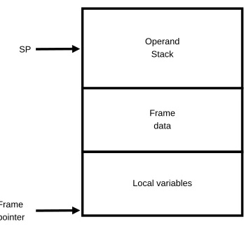
Figure 2.6: Java frame data structure on the Java stacks.
a new Java stack frame being pushed to store the local information and the operand stack for that method. When the method completes, the Java stack frame is popped. PC registers store the virtual program counter, which points to the code being executed and the stack pointer of the operand stack for the execution of a thread. The native method stack is used to record the native method call information. The native methods are used to implement platform dependent functions.
The Java stack records the history of method calls for the execution engine. For each method call, there exists a Java frame, which includes local variables for the method, frame data, and an operand stack for the computation (see Figure 2.6). The frame data may include program counters (PC) & stack pointer (SP) of the called method and/or PC and SP of current method.
2.3.2
Execution Engine
In this dissertation, we only consider the interpreter for the Java Virtual Machine implementation. When the execution engine is implemented using an interpreter, in-direct branches are needed in order to jump to their corresponding segments inside an interpreter loop which implement the functions of bytecode instructions. In modern hardware processors, the indirect jumps are poorly predicted [EG03], which leads to poor performance of a Java interpreter.
2.3.3
Java Bytecode Instruction Set
The Java Virtual Machine (JVM) is stack-based and its instructions manipulate the operand stack of a Java stack frame on the Java stack. For a stack-based instruction set, the operands of an instruction are implicit and any computation has to be done through a stack.
Java bytecode instructions can be put into the following categories:
• Stack load/store instructions - includes all instructions which load values from
the local variables onto the operand stack and instructions which store values from the operand stack to the local variables.
• Constant instructions - load constants onto the operand stack.
• Flow control instructions - includes if, switch and unconditional branch
instruc-tions.
• Arithmetic/logical instructions - includes different types of arithmetic
instruc-tions.
• Object access instructions - includes array access instructions and class/object
field access instructions
• Method call and return instructions - includes all invoke static (class) and object
method call and return instructions.
• Stack manipulation instructions - includes all those instructions which duplicate
stack items on the operand stack and stack pointer manipulation instructions
• Exception handling instructions - includes all those instructions which support
• Threading support instructions - includes all those instructions which support
Java threads, such as thread synchronization.
• Type testing/casting
2.4
Modern Processor Architecture
Modern processors’ performance has been improved dramatically since the first gen-eral purpose computer was created. This performance improvement came from the advancement of the technology used to build the processors and innovative computer design. In this section, we are going to introduce some of the concepts and terms related to this dissertation.
2.4.1
Cache Memory
key1
key2
hash function
Figure 2.7: Direct-mapped cache
N sets M elements
key1
key2
hash function
IF ID EX MEM WB
time
stage 1 stage2 ...
IF ID EX MEM WB
IF ID EX MEM WB
IF ID EX MEM WB
IF ID EX MEM WB
op1
op2
op4
op5 op3
Figure 2.9: Classic processor pipeline
2.4.2
Pipelining
Even though computer processor architecture has become very complex in modern processor, the logical steps to execute an instructions remain the same:
• Fetch an instruction from the main memory
• Decode the instruction
• Fetch the needed operands (data) from memory
• Execute the instruction
• Write the results of the instruction back to the memory.
(1) predict: T
(0) predict: N
T N
T N
Figure 2.10: Dynamic 1-Bit Predictor. When the one-bit state is 1, the branch is predicted taken. When the state is 0, the branch is predicted to be not taken.
2.4.3
Branch Prediction
Instructions in a programs are not generally independent of each other. There exist data dependencies and control dependencies (branch effects) [USS97] between the in-structions. When a branch instruction passes through the pipeline, the path to be taken is not determined until the instruction is executed, which will stall the whole pipeline. Speculative instruction execution tries to solve this problem by predicting the branch direction and continuing execution in the predicted direction. Branch prediction accuracy has a large impact on the performance of a pipelined processor.
Branch instruction can be a conditional branch or an unconditional branch. Condi-tional branches have two branch targets: taken (T) or not-taken (N). Static predictors always predict the branches to be taken or not-taken, or BTFN (Backward Taken; Forward Not Taken). Dynamic predictors use the previous branch execution results to make future predictions, which allow branch predictors to adapt to the characteristics of an application. As shown in Figure 2.10, a 1-bit predictor uses one bit to represent the state of each branch instruction and uses the state to make a prediction. The bit for each state is usually stored in a table, such as a branch target buffer (BTB) and the branch instruction address is used to look up the state in the table. When the state is one, the branch is predicted to be taken. After the branch is actually resolved (taken or not taken), the state will be updated as shown in Figure 2.10. A 2-bit predictor uses 2-bits to represent the state of each branch instructions and use the state to make future predictions, as shown in Figure 2.11.
(10) predict: T (01) predict: N T N N (11) predict: T T N (00)
predict: N N
T
N
T
[image:33.612.230.408.250.414.2]saturated unsaturated unsaturated saturated
Figure 2.11: Dynamic 2-Bit Predictor. When the significant bit of the state is 1, the branch is predicted taken. When the significant bit of the state is 0, the branch is predicted to be not taken.
0
1 1 1
Branch history register shift direction 1 0 sign of latest resolved branch 0 1 0000 1011 0 0 1111 ... ... msb lsb index predict (0) Not taken
Figure 2.12: Two-level adaptive branch predictor.
branch. The two-level adaptive predictor, as shown in Figure 2.12, takes into account the branch history before the one currently being predicted. The branch history register holds the history of previously executed branches. Each time a branch’s direction is resolved, its direction (taken: 1 or not taken: 0) is shifted to the least significant bit of the branch history register. The branch history register is used as an index into the branch pattern table, which holds a 2-bit counter (state) similar to Figure 2.11.
With advancements in manufacturing technology, which allows larger predictors, and research in branch prediction, the two-level adaptive branch predictor can give a prediction accuracy of over 90% [USS97].
more than one target, which may depend on some computed value. Indirect branches are not very common (less than 1% [DH98]) in regular programs. However they are quite common (up to 13% [EG01]) in the implementation of interpreters. Indirect branches can be unpredictable (up to 95% [EG03]) when a branch target buffer (BTB) is used.
2.5
Conclusion
In this chapter, we have presented the concepts relating to virtual machines and exam-ined the internal structure of the Java Virtual Machine. Branch prediction in modern pipelined processors is critical to their performance. Various predictors have been introduced.
Chapter 3
Literature Survey
3.1
Introduction
As discussed in the last chapter, an interpreter is one of the ways to implement the execution engine of a HLL VM. In this chapter, we examine the interpreter optimiza-tions relating to the dispatch cost reduction, the stack caching for stack-based VMs, register-based VMs, indirect branch prediction, and trace cache.
Source (Virtual) ISA
Execution Engine (Interpreter)
[image:35.612.242.399.405.556.2]Host (Native) ISA
3.2
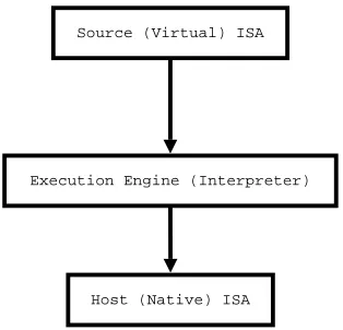
Virtual Machine Interpreters
Interpreters have a long and rich history. As shown in Figure 3.1, an interpreter can understand the source (virtual) ISA (usually referred to as bytecodes) and interpret those virtual ISA on a hosted platform. The interpreter-based VM abstracts away the underlying details of hosted platforms and makes the implemented high-level program-ming language portable across different hardware platforms as long as the VM has been ported to them.
There are many different types of interpreters. Some interpreters (MIPSI [SA97] and SimpleScalar [ALE02b]) simulate the ISA of new hardware, which does not yet exist, or to port binary applications compiled for one hardware platforms to run on another one. Some other interpreters (Java [LY99], Perl, Tcl, Lua [IdFC05]) are used to implement higher level programming languages.
When an interpreter is used to implement a high-level language, there are two ways to convert the high-level source code into a sequence of virtual machine instructions or bytecodes understandable by the interpreter. The translation of the source code into VM code can be either off-line (JVM [LY99]) or during runtime (Perl and Lua [IdFC05]). VM instructions for higher-level portable languages like Java are usually designed with the intention of easing interpretation. The opcodes are usually encoded with one byte (256 possible VM instructions) in interpreters, such as Java [LY99] and Smalltalk [GR83].
An interpreter is an attractive option for VM implementation because it is easy to implement and port to different platforms. However, an interpreter suffers from the drawback of low performance when compared to native code compiled directly from the source programming language. Many researchers [RLV+
96, EG03, BVZB05, PR98] have studied ways to improve the performance of an interpreter. We will focus on the two categories of improvement which are relevant to our research in this dissertation. The first category is related to interpreter implementations, such as the dispatch mecha-nism. The second category is related to the VM instruction architecture design choices, such as the choice between virtual register machine instruction format or virtual stack machine one.
...
iload a
iload b
iadd
istore c
... VM Code
Interpreter Engine Thread Stack
Heap IP
(1) Fetch
Hardware (2) Decode
(3) Fetch Operands (5) Store result
[image:37.612.164.477.74.281.2](3) Fetch Operands (5) Store result (4) Execute
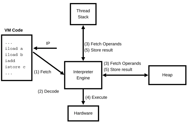
Figure 3.2: The execution cycle of a VM instruction by an interpreter. (1) Fetch an instruction pointed by IP, (2) Decode the VM instruction by finding out its implementa-tion, (3) Fetch the source operands for the instrucimplementa-tion, (4) Execute the implementation of the instruction inside the interpreter loop, (5) Store the results back. The thread stack holds the virtual register and the operand stack for a particular method call. The heap will store more global data structures like an object representation
typedef enum {
add /* ... */
} Opcode;
void engine()
{
static Inst program[] = { add /* ... */ };
Inst *ip = program;
int *sp;
for (;;)
switch (*ip++) {
case add:
sp[1]=sp[0]+sp[1];
sp++;
break;
/* ... */
}
[image:38.612.185.442.82.317.2]}
Figure 3.3: switch interpreter dispatch. Source: [EG03]
3.3
Dispatch Cost Reduction Techniques
Interpreter instruction dispatch involves extracting the opcode of an instruction and finding the corresponding interpreter segment which implements the instruction. In-struction dispatch is an overhead of executing VM inIn-structions. For fine-grained VM instruction set architecture like Java bytecodes [LY99], more than 40% [RLV+
96] of executed native instructions can be related to instruction dispatch. Moreover, in-struction dispatches perform a large number of indirect branches (3.2% - 13% of all executed native instructions) and the high misprediction of indirect branches are very expensive (62% of execution time without a predictor) [EG03]. Much research [Bel73, EG03, BVZB05, PR98] has been carried out to minimize the cost of dispatch.
3.3.1
switch
Dispatch
The most common and easy way to implement interpreter dispatch is by using a big
switch statement inside a loop, as shown in Figure 3.3, with one switch label for each VM instruction inside the loop, such as add.
$L2: #for (;;)
lw $3,0($6) #$6=instruction pointer
#nop
situ $2,$8,$3 #check upper bound
bne $2,$0,$L2
addu $6,$6,4 #branch delay slot
Sll $2,$3,2 #multiply by 4
addu $2,$2,$7 #add switch table base ($L13)
lw $2,0($2)
#nop
j $2
#nop
...
$L13: #switch target table
.word $L12
...
$L12: #add:
...
j $L2
#nop
load opcode range check? load jump address from the switch table
indirect branch
[image:40.612.220.425.77.328.2]add ... ...
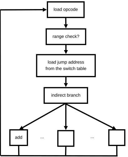
Figure 3.5: switch-based interpreter flow diagram
assembly code is shown in Figure 3.4. First, the opcode of a VM instruction is loaded. The opcode is checked to see if it is within the range of available switch labels. Then the opcode is used to look up the jump address (corresponding to a VM instruction label) in a switch table. Finally one indirect branch jumps to the VM instruction’s implementation. Moreover, there will be a direct jump at the end of each case (a VM instruction implementation) to go to the beginning of the interpreter loop. Because only one indirect branch exists in the whole interpreter to jump to all the labels (instruction implementation), there will be only one entry in the branch target buffer (BTB) in most modern processor. The BTB will store the previous target of an indirect branch, which will provide the target for the following execution of the same indirect branch. Unless all instructions are the same in the VM code streams, the BTB will give incorrect predictions.
As shown in Figure 3.5, the jump to an instruction implementation segment in an interpreter loop is translated to only one indirect branch on a hosted platform when
typedef void *Inst;
typedef enum {
add /* ... */
} Opcode;
void engine()
{
static Inst program[] = { add, /* ... */ };
static Inst dispatch_table[] = { &&add /* ... */ };
Inst *ip = program;
int *sp;
goto dispatch_table[ip++]; /* dispatch first VM inst. */
add:
sp[1]=sp[0]+sp[1];
sp++;
goto dispatch_table[ip++]; /* dispatch next VM inst. */
}
Figure 3.6: Token-threaded interpreter dispatch. Source: [EG03]
a pipelined processor speculatively executes in the wrong direction [EG03]. There is much research on restructuring the interpreter loop to improve the indirect branch prediction of an interpreter, such as direct-threaded code [Bel73, Ert93] or to reduce the number of indirect branches by reducing the number of executed instructions, such as superinstructions [Ell05, EGKP02, CGEN03].
3.3.2
Token-Threaded Dispatch
characteristic of threaded code is that there is no need for a loop to execute the VM code. When the execution of one VM instruction ends, the dispatch code at the end of the instruction will dispatch to the next instruction in the code stream. There are multiple indirect branches (one for each VM instruction) in the native code compiled from the interpreter. On modern processors with a BTB, multiple entries exist in the BTB. As long as a given instruction will be followed by the same instruction next time in the code stream, a correct prediction will be made.
Compared to switch dispatch, the range-check1
and the direct jump are elimi-nated. One big advantage of token-threaded dispatch is to keep the bytecode program unchanged while benefiting from better indirect branch prediction.
3.3.3
Direct-Threaded Dispatch
Direct-threaded dispatch [Bel73, Ert93] goes one step further to eliminate the table lookup operation in the token-threaded dispatch, as shown in Figure 3.7. In order to do this, the VM code needs to be transformed into direct-threaded code, in which the opcodes (usually one byte) for VM instructions will be changed into the addresses (usually 4 bytes on 32-bit hardware platform) of instruction implementation in the in-terpreter. Direct-threaded dispatch uses memory addresses as the opcodes of instruc-tions to jump to their corresponding implementation directly. The main drawbacks of this approach are an additional translation step and the larger code size for the VM instruction representation, because the size of absolute memory addresses in a 32-bit processor is 4 bytes while it is 8 bytes on a 64-bit processor.
An inspection of MIPS assembly code (Figure 3.8) shows that the direct-threaded dispatch overhead is only four native instructions while switch dispatch, as shown in Figure 3.4, requires eight native instructions.
3.3.4
Indirect-Threaded Dispatch
Indirect-threaded dispatch [Dew75] uses an additonal level of indirection to achieve a space saving for VM code. Unlike direct-threaded dispatch [Bel73], the opcode of a
1
The range check is created by the compiler to make sure that the target of the indirect branch is one of the switch label before a table loop-up is carried out. In many cases, the designer of an
typedef void *Inst;
void engine()
{
static Inst program[] = { &&add /* ... */ };
Inst *ip = program;
int *sp;
goto *ip++; /* dispatch first VM inst. */
add:
sp[1]=sp[0]+sp[1];
sp++;
goto *ip++; /* dispatch next VM inst. */
}
Figure 3.7: Direct-threaded interpreter dispatch. Source: [EG03]
lw $2,0($4) #get next inst., $4=inst.ptr.
addu $4,$4,4 #advance instruction pointer
j $2 #execute next instruction
#nop #branch delay slot
VM instruction points to a struct. Thestruct has an address pointer to the actual VM instruction implementation and the immediate values and/or operand(s) for the instruction. Effectively, the VM code will be translated into a list of pointers to the structs. Repeating operand(s) and/or immediate value(s) will contribute to the space saving. However, because of a level of indirection, indirect-threaded dispatch is not be as efficient as direct-threaded dispatch.
3.3.5
Static Superinstructions
Static superinstruction optimization [Bad95, Hug82, Pro95, Ell05, CGE05] tries to find recurring instruction sequences and combine them together to form new superinstruc-tions. The superinstruction carries out all the operations of the original sequence of component instructions. Thus all the dispatches within a superinstruction are elimi-nated. Moreover, the compiler will be in a better position to optimize the implementa-tion segments of a superinstrucimplementa-tion because of longer native code sequences. The main difficulty with superinstruction optimization is to find the right recurring sequences (superinstructions). Dynamic profiling examines the executed sequences of VM in-structions of applications and tries to find the most frequently occurring sequences. The main problem with dynamic profiling is that the recurring sequences discovered in this way are highly biased, which means the superinstruction found in a applica-tion could be totally useless in another one. On the other hand, static profiling only examines the static code to discover the frequently recurring sequences. Casey et al.
[CGE05] found that static profiling usually finds a better set of superinstructions and hundreds of superinstruction are required to gain good performance improvement. For most bytecode VMs, the size of opcodes is only one byte, which allows for 256 opcodes, most of them already used by VM instructions. So superinstruction optimization works best with direct-threaded code because opcodes in VM instructions are encoded with address pointers (4 bytes on 32-bit platform and 8 byte on 64-bit platform) and allow more than 256 opcodes (instructions).
3.3.6
Inline-Threaded Dispatch
iadd impl. dispatch code
iload impl. dispatch code
istore impl. dispatch code (1) iload a
(2) iload b (3) iadd (4) istore c
VM Code
Interpreter Core Native Code
istore impl. iadd impl. iload impl. iload impl.
Dynamically Generated Native Code Sequence
(1) (2)
(3) (4)
Figure 3.9: Inline-threaded dispatch. The VM instruction sequence to implement the arithmetic assignment: c = a + b is on the left. The interpreter core native VM instruction implementation is copied to form the corresponding native code sequence to carry out c = a + b
the native code to carry out the function of that VM instruction and the native code required to dispatch to the next VM instruction (Figure 3.9). For a straight line ba-sic block of VM instructions, inline-threaded dispatch [PR98] dynamically copies the native executable code of the interpreter code segments for VM instructions in the se-quence without the dispatch native code and concatenates the copied executable code together to form a straight line of native code. Then the new dynamically created native code for the straight line of VM instruction will be executed whenever the same sequence of VM instructions needs to be executed. In this way, all the instruction dispatch code is eliminated for the sequence. Figure 3.9 shows the VM instruction se-quence to do c = a + b: iload a, iload b, iadd, istore c. Generally speaking, one block of native code will usually be created for each basic block in VM code.
Inline-threaded dispatch is probably the fastest dispatch mechanism so far. How-ever, it sacrifices portability and code size to gain performance benefits for the inter-preter.
3.3.7
Context-Threaded Dispatch
Figure 3.10: Context-Threaded VM interpreter Sequential Code. Source: [BVZB05]
straight line of VM code is converted into a sequence of function calls (Figure 3.10). Now, the costly indirect branches are replaced with function calls and returns, which take advantage of the hardware return-address stack to make very accurate prediction. Inlining is required to handle the VM branch instructions. VM call and return in-struction are handled specially to align the virtual PC and hardware PC (Figure 3.11). Native code generation is required during runtime to generate the native functional calls, handle VM branches and VM calls/returns.
3.3.8
Vmgen Interpreter Generator
Interpreters for different dispatch mechanisms share a lot of common code templates. Vmgen [EGKP02] is an interpreter generator which can be used to produce an inter-preter with switch, token-threaded, and direct-threaded dispatches. The generator uses an instruction specification file, either in stack-format or register format, as an input. It mainly supports stack-based architectures, and includes stack-caching and superinstruction.
3.3.9
Summary
Figure 3.12 shows all the dispatch cost reduction techniques discussed in this section in terms of efficiency and complexity. Generally speaking, the more complex a dis-patch method is, the less portable it is. The switch statement is the least complex and most portable dispatch method for building an interpreter. When ANSI C is the only available programming environment, switch is the only option. On the other end of the spectrum, inline-threaded and context-threaded are the most complex and efficient dis-patch mechanisms. It requires more effort to port inline-threaded and context-threaded interpreters and specific hardware platform knowledge is required. Superinstructions usually require direct-threaded dispatch to allow more than the 256 opcodes available in bytecodes to achieve the benefits of dispatch reduction.
3.4
Interpreter Stack Caching
Complexity Efficiency
switch
direct-threaded
inline-threaded superinstruction
indirect-threaded token-threaded
context-threaded
• Accessing operands of the VM instruction
• Performing the function of the VM instruction
• Dispatching to the next instruction
Most virtual machines (Pascal P-Code VM [PD82], Smalltalk [GR83], Java [LY99]) and Microsoft.NET CLR [ECM02]) use stack-based VM instruction architecture. VM instructions implicitly access the operands from the top of an operand stack using a stack pointer (SP) and/or the local variables. The operand stack and the local variables are typically an array of memory locations.
For a stack-based VM, all computation is done through the operand stack. For example, the arithmetic expression c = a + bwill produce the Java bytecode instruc-tions: iload a, iload b, iadd, istore c. The first two instructions push the num-bersaandbfrom local variables onto the operand stack. These two iloadinstructions will first load the local variables (memory locations) into the physical registers of a real processor and save the values back to the operand stack (memory location). The iadd instruction pops the values of a and b from the operand stack (memory locations →
physical registers), adds them, and pushes the results back onto the operand stack (move from a physical register into a memory location). Theistore cinstruction will load the value from the operand stack (memory location) into a register and then save the value into a VM local variable (memory location). There is a lot of data traffic between the physical registers and memory locations (the operand stack and the local variables).
One important characteristic of stack-based VMs is that the top of an operand stack is consumed very quickly by the following instructions. Instead of moving the data between physical processor registers and the operand stack (main memory), stack-caching [Ert94, Gri01, PWL04] for a stack-based VM uses physical registers in a real processor as an extension to the operand stack to keep the topNelements of the operand stack. For example, the results of the iadd do not have to be saved on the operand stack and later to be loaded again to move the result to the local variable c. Stack caching has the potential to cut down the traffic between the physical registers and the operand stack (memory locations).
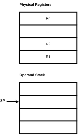
registers. The register cache can overflow and underflow. Overflow happens when there are already N values stored in the register and a new value is pushed onto the operand stack. Underflow happens when an instruction needs to access some operands which are not in the register cache. There are two ways to maintain the register cache. The first way [PWL04] is to keep the top of the operand stack in a fixed register, such as the register Rn, as shown in Figure 3.13. When a new value is pushed onto
the operand stack, the existing values are shifted down: Rn → Rn−1, ..., R2 → R1, R2 →(SP + 1). The number of shifts depends on the cache state. If the cache is full,
the shift will go all the way and one item will be moved to the operand stack. On the other hand, the values from the operand stack will be loaded into the register cache if it is not full after the execution of an instruction. The second way [Ert94] is just to regard the register cache as an integral part of the operand stack. R1 is the next item
above the item pointed by the stack pointer (SP), as shown in Figure 3.13. New items pushed will be loaded into R1, R2, ..., and Rn. If the register cache is full, the shift
operation will still happen. There will be no prefetching to fill the register cache from the operand stack when the register cache is not full.
In different cache states, the techniques used to access the operands of instructions can be different. There are two schemes [Ert94] to implement stack caching in an interpreter: static stack caching and dynamic stack caching. Static stack caching uses the compiler to analyze the cache states and produce the necessary VM code to maintain the cache state and dispatch to the next instructions. Dynamic stack caching needs one interpreter loop for each register cache state. The interpreter will keep track of the cache state and dispatch to the appropriate interpreter loop. One problem with this approach is code explosion because of the replication of the same interpreter for different cache state. Code sharing [PWL04] can can help to solve this problem.
An interesting variation of stack caching [Gri01] uses the data types of the item in the register cache as the cache state. Only one item is kept in the register. However, the item will be in different registers when the data type is different.
... Rn
R1 R2
Physical Registers
Operand Stack
[image:51.612.243.398.75.350.2]SP
Figure 3.13: Stack caching
3.5
Register Machines
Current computer processors (Intel, AMD, PowerPC) use register-based architectures. On the other hand, virtual machine (VM) implementations have been predominately stack-based (Smalltalk [GR83], Java [LY99], and Microsoft.Net CLR [ECM02]) since Pascal’s P-machine [PD82].
3.5.1
Stack vs. Register Instruction Sets
Real Stack Computers
Stacks are widely used in computer science. An evaluation stack is used to compute the value of arithmetic expressions. In a processor, a call stack saves the traces of subroutine calls and returns.
produced by an instruction will be pushed onto the operand stack. There are two important instructions load and store. The load instruction pushes a value from an arbitrary RAM location onto the top of the computational stack and thestore instruc-tion saves a value from the top of the computainstruc-tional stack into a memory locainstruc-tion. The main advantages of a stack-based instruction set are:
1. Very high code density compared to other form of instruction sets (such as register-based instruction sets)
2. Simplicity of the instruction set
3. Simple compiler implementation to generate stack-based code from source pro-gramming language.
Real Register Computers
A register machine uses the registers to store the operands (temporaries/result) of instructions (computation). In a register machine, the operands (register/memory location) must be encoded as part of an instruction. Most compilers for register ar-chitectures will use registers as much as possible because accesses to the registers are faster and a limited number of registers allow for shorter encoding of the instructions. Generating code for a register machine is more complex and a sophisticated register allocator is often needed to make best use of a limited number of registers to maximize the performance of a source program.
Comparison
3.5.2
Register-Based Virtual Machines
There have been several virtual machines (Dis [WP97], Perl 6 [Fag05] , Lua 5.0 [IdFC05], Mamba [PA02], and Rain VM [Bro06]) implemented with register instruction set architectures.
Dis
Dis [WP97] is a virtual machine with a register architecture created at Bell Labs to support application portability. The extra memory traffic of a stack-based VM was given as the reason for using the register-based VM. From their experiences of implementing a stack computer in the AT&T Crisp microprocessor, Winterbottom et al. [WP97] believed that a stack architecture is inherently slower that a register-based machine. Moreover, it was argued that closer resemblance of VM instructions and real processor instruction allows easier JIT compilation. Dis uses a three-address instruction encoding. The first source and the last destination operand can be memory addresses or arbitrary constants while the second operand is limited to smaller constants and stack offsets to reduce code size. Each operand specifies an address either in the stack frame of the executing procedure or in the global data of its module.
The Parrot Virtual Machine
Perl 6 [Fag05] moves away from its earlier stack-based versions to a new register archi-tecture. It is intended to support multiple languages including Perl itself. It has many higher-level features such as objects, thread synchronization support and garbage col-lection. The designers [Fou07] of Perl 6 give some of the following reasons for moving to the register architecture:
1. Fewer register-based VM instructions are required than those of a stack VM.
2. More research in optimization for register-based hardware to take advantage of.
3. Break away from the tradition of stack VM implementation to innovate.
OP A B C
0 ... 5 6
OP A Bx
OP A sBx
... 13 14 ... 22 23 ... 31
Figure 3.14: Lua 5.0 instruction format. Source: [IdFC05]
evolution, the number of registers became unlimited to eliminate register spills. The virtual registers of the Parrot VM are stored in a register frame. These frames can be pushed and popped onto a virtual register stack.
Lua 5.0
Lua is a scripting language widely used in game industry. Lua 5.0 [IdFC05] moved to register-based architecture partly because of earlier work on register machines in our group. There are 35 instructions in Lua’s virtual machine. Virtual registers are kept in the run-time stack, which is implemented with an array. Constants and upvalues are also stored in arrays. Lua 5.0 uses 32 bits instruction encoding, as shown in Figure 3.14. The first 6-bits are the opcode. The next 8 bits are the first operand (A) and always present. The second (B) and third (C) operands are 9 bits. These second and third operands can be combined into one larger operand. Performance comparisons between Lua 5.0 and 4.0 show around a 20% improvement.
Mamba
a 12-bit operand encoding, enabling accesses to all of the registers.
Rain Virtual Machine
The Rain VM [Bro06] is implemented with a register architecture for concurrency. The decision was made based on research done for this dissertation [SGBE05] to demon-strate that a register interpreter-based VM has better performance than a stack VM. In the Rain VM, the instruction set uses 32-bits to encode two-address instructions. The first byte is the opcode and the second one is a sub-opcode. The third and fourth bytes are source and destination operands. The registers are addressed by one byte (256 registers). The Rain VM initially allocates 8 or 16 registers. The VM can increase the number of registers as needed. It uses context pointers to quickly switch between threads. Part of the context information is related to register blocks. It is not clear from the paper whether Rain VM creates a new register block or saves/restores the register block for each method/function call/return.
3.5.3
Virtual Register Organization
3.5.4
Java Virtual Machine Related Research
Davis et. al. [DBC+
03, GBC+
05] began the first large-scale quantitative study of stack vs. register instruction set architectures on the Java virtual machine. They translated the stack-based Java bytecodes into register ones. All the stack push/pop instructions were translated into move instructions. A simple copy propagation algorithm was applied to eliminate the redundant move instruction in the register architecture. Of the resulting register code, the number of executed VM instructions could be reduced by 35% while the bytecode loads increased by 45%. There were no timing results.
3.6
Indirect Branch Prediction
Branch instructions in a program are used to transfer the execution of a program from one part to the other. There are mainly two types of branch instructions: conditional branch instructions and unconditional branch instructions. Unconditional branch in-structions can be further divided into unconditional direct jump inin-structions and un-conditional indirect jump (indirect branch) instructions. A un-conditional branch instruc-tion has two direcinstruc-tions of program control flow: the fall-through target (the next instruction) and the jump target (encoded in relative or absolute address as part of the instruction). An unconditional direct jump has only one target. An indirect branch (indirect jump) is a type of branch instructions, whose targets are determined by a computed value in a register. Indirect branch instructions in a processor can have more than two possible branch targets.
On modern wide-issue and deeply pipelined processors, speculative execution be-yond branch instructions is necessary to better take advantage of available hardware resources and gain more benefits from instruction-level parallelism. The penalty is very high when the speculative execution goes in the wrong direction. When this happen, all the work done beyond a branch has to be flushed and restarted in the new direction of execution.
. . .
. . .
. . .
Branch Instruction
Address
Branch Prediction
Statistics
[image:57.612.145.494.77.285.2]Branch Target Address
Figure 3.15: Branch target buffer organization. Source: [PS93]
corresponding entry. For an indirect branch instruction, the direction of the branch is always taken. However, the target address of corresponding entry will be updated if the predicted target address is incorrect.
The default BTB misprediction update policy is not very effective (51.8% prediction rate for SPECint 95 [CHP97]). It will always predict the previous target address as the target address of the same indirect branch instruction when it is executed again.
3.6.1
BTB with 2-bit Counters
Galder and Grunwald proposed a BTB with 2-bit counters (BTB-2bc) to improve the indirect branch prediction for C++ programs [CG94]. BTB-2bc stores a 2-bit counter for each indirect branch in the BTB. The branch target will only be updated after two consecutive mispredictions of the branch target. The scheme reduces the misprediction rate from an average of 28.1% for the standard BTB to 24.9%. The BTBs with 2-bit counters perform well when a few targets dominate and there is only an occasional target change. Polymorphic branches occasionally switch their target, a situation observed in object-oriented programs [AH96]. However, Chang et al. [CHP97] found that 2-bit strategy is not very successful in predicting the targets of indirect branches in C programs such as the SPECint95.
3.6.2
2-Level Prediction of Indirect Branches
A 2-level conditional branch predictor can reach the prediction rate of 95-97% [YP93]. The success of 2-level conditional branch prediction inspired an interest in indirect branch prediction research [CHP97, DH98].
... History Information
Branch Address
hash function
Target Cache
Target address
Figure 3.16: Structure of a Tagless Target Cache. Source: [CHP97]
(set-associative, see Section 2.4.1) target cache , as shown in Figure 3.17, solves the in-terference problem by first indexing into a set in a set-associative target cache. Then a tag, usually the branch address, is used to select the right indirect branch instructions. The pattern history uses the target address of previous branches. The pattern history using the indirect branch target address is particularly effective for SPECint95 Perl, which is an interpreter. Change et al. [CHP97] showed that a 16-way set associative tagged target cache with pattern history can reduce the execution time of gcc and Perl by 12.66% and 4.74% respectively.
History Information
Branch Address
Index function
Set Tag
? ?
[image:60.612.114.529.74.300.2]Branch Target
Figure 3.17: Structure of a Tagged Target Cache. Source: [CHP97]
entries.
It is important to note that the past path/pattern history provides context for improving indirect branch prediction. The global path history consisting of previous indirect branch target addresses performs better than other history schemes [DH98, CHP97]. For an interpreter, the global path history helps to align the virtual code sequence to the predictor’s history state.
3.7
Trace Cache
The pipeline of a superscalar processor can be divided into instruction fetch/decode and instruction execution, as shown in Figure 3.19. The instruction issue buffers are the interface between instruction fetch mechanism (producer) and instruction execution mechanism (consumer). Instruction fetches are usually done sequentially by increment-ing the instruction pointer. Branch instructions redirect the instruction fetchincrement-ing to new locations. Thus branch instructions act as feedback to the instruction fetch mechanism from the instruction execution mechanism.
Global History Pattern
P targets Branch Address
History Table
Figure 3.18: Two level indirect branch prediction. Source: [DH98]
Instruction Fetch & Decode
Instruction Execution
Instruction Issue Buffer(s) branch outcomes/jump addresses

![Figure 3.3: switch interpreter dispatch. Source: [EG03]](https://thumb-us.123doks.com/thumbv2/123dok_us/8812839.919193/38.612.185.442.82.317/figure-switch-interpreter-dispatch-source-eg.webp)
![Figure 3.10: Context-Threaded VM interpreter Sequential Code. Source: [BVZB05]](https://thumb-us.123doks.com/thumbv2/123dok_us/8812839.919193/46.612.142.501.363.611/figure-context-threaded-interpreter-sequential-code-source-bvzb.webp)
![Figure 3.15: Branch target buffer organization. Source: [PS93]](https://thumb-us.123doks.com/thumbv2/123dok_us/8812839.919193/57.612.145.494.77.285/figure-branch-target-buer-organization-source-ps.webp)
![Figure 3.17: Structure of a Tagged Target Cache. Source: [CHP97]](https://thumb-us.123doks.com/thumbv2/123dok_us/8812839.919193/60.612.114.529.74.300/figure-structure-tagged-target-cache-source-chp.webp)
