Embedded Controller for Radar based Robotic
Security Monitoring and Alerting System
V. Ramya
Assitant Professor Dept of Computer Science and Engineering Annamalai University
Chidambaram,Tamilnadu
B. Palaniappan
Dean,FEAT,Head Dept of Computer Scienceand Engineering,AnnamalaiUniversity
Chidambaram,Tamilnadu
Subash Prasad
Dept of computer science and Engineering,AnnamalaiUniversity
Chidambarm,Tamilnadu
ABSTRACT
In the mobile robot navigation, the ultrasonic sensors have been widely used for the obstacles detection and map building because of its cost and efficiency. Generally sensors are used to increase the accuracy of the obstacles position and decrease the time. In this paper an ultrasonic sensor is interfaced on to a stepper motor which will be constantly revolving and detecting the values of any obstacle in its path in all the 360°. In Stepper motors, on the other hand, effectively have multiple "toothed" electromagnets arranged around a central gear-shaped piece of iron. The electromagnets are energized by an external control circuit, such as a Microcontroller. To make the motor shaft turn, first, one electromagnet is given power, which makes the gear's teeth magnetically attracted to the electromagnet's teeth. When the gear's teeth are aligned to the first electromagnet, they are slightly offset from the next electromagnet. In each angle the position of the stepper motor is sent to the monitoring end along with ultrasonic values serially so that we are able to track the object coming from various distances. At the monitoring end, the values of step position for each rotation is received along with the ultrasonic values indicating the user the exact position of intruder or object in the exact direction. And also video is delivered to the monitoring end to know the situation of current scenario. If the value of the ultrasonic sensors increased to its range then the SMS gateway is activated and a security SMS is sent to the authorized person. This project can be utilized for security purposes in extreme weather conditions which replace human surveillance and thereby save the human lives.
Keywords
Embedded controller, mobile robot, sensors, SMS gateway, stepper motor
1. INTRODUCTION
The proposed robot can be used for detecting the obstacle and send the information to the local server. The robot consists of DC geared motor which helps in smooth movement of robot and provides proper control on the robot movement. This project is developed to help humans and reducing the risks of their lives. In this project the robot is controlled manually through the monitoring end. The robot can move right, left, forward and backward. If an obstacle or an intruder comes in-front of the robot, the security alert information is immediately send to the
local server and then the robot automatically turns to other side and starts surveillance.
1.1. Artificial Intelligence
Artificial Intelligence generally deals with helping machines find solutions to complex problems in a more human-like
fashion. This generally involves borrowing characteristics from human intelligence, and applying them as algorithms in a computer friendly way. A more or less flexible or efficient approach can be taken depending on the requirements established, which influences how artificial the intelligent behavior appears. AI research is allowing us to understand our intelligent behavior. Humans have an interesting approach to problem-solving, based on abstract thought, high-level deliberative reasoning and pattern recognition. Artificial Intelligence can help us understand this process by recreating it, then potentially enabling us to enhance it beyond our current capabilities. There are many different approaches to Artificial Intelligence, none of which are either completely right or wrong. Some are obviously more suited than others in some cases, but any working alternative can be defended. Over the years, trends have emerged based on the state of mind of influential researchers, funding opportunities as well as available computer hardware.
2. RELATED WORK
Baifan Chen [1] has proposed a system to detect the obstacle in unknown environments using laser radar. This system filtered the noisy data, sensor readings are mapped into the real world coordinate systems to build grid maps are maintained. By comparing the state of the same grid cell in the three consecutive grid maps and considering the state of the eight-neighbor cell, obstacles are identified.
Dong-Won Jung [2] has developed the mobile robot navigation in which the multiple ultrasonic sensors are used to increase the accuracy of the obstacles position and decrease the scan time and get the various obstacles information by processing data received from multiple sensors .And the new developed ultrasonic sensor system that is composed of the driver/receiver signal processing hardware based on DSP. And the developed APIs that can be used with this sensor system
A.Cherubini [3] has developed a system that that provides remote control of home installed appliances including the Sony AIBO, commercial robot. The development of the project is described by focusing on the design of the robot navigation system. Single step, semi autonomous and autonomous operating modes have been realized to provides different levels of interaction with AIBO. Automatic collision avoidance is integrated in all cases
controller to formulate and execute the desired path movement. In vertical distance from a work piece surface was measured and utilized to perform on-line trajectory adjustment for the robot cutting-tool motion.
3.
EMBEDDED
SYSTEM
DESIGN
PROCESS
The system design process consists of the following steps as shown figure 1 and these steps are referred as the major levels of abstraction in the design process. There are two types of designing methods, one is Top-down method and the other is Bottom-up method. This work adopts the Top-down method.
Fig1: Major levels of abstraction in the design process
The Requirement phase is the first level in which the functional and non functional requirements like performance cost, physical size and weight and power consumption for developing the proposed project were analyzed.
The Specification level reflects the requirements specified in the first level, it says only what the system does and not how to implement. In this proposed work the specification of the robotic security system includes,
o Data received from Zig-bee o User interface
o Ultrasonic sensor data to the Microcontroller
o Video streaming o SMS gateway
The Architecture level is a plan for overall system that will be used to design the components that make up the architecture [5]. The system architecture of the proposed work is shown in figure 2. The system architecture further refined in to Hardware and software architecture to ensure all specifications. The hardware and software architecture is shown in figure 3 and fig 4 respectively. It shows the components required to build the project. The architecture should satisfy the functional and non functional requirements.
Figure3 shows the hardware module in which the dc motor switches to relay according to the robot movement and relay
connected to the microcontroller which sends the data through the zig-bee transmitter using UART and the receiver zig- bee receives the data and displays the output.
Fig2: System Architecture of the Proposed System
Figure4 shows the software architecture which is interfaced with the hardware components. The user interface design provides the command to the microcontroller and the microcontroller switches the control to the relay and operation is done. User interface design is implemented through the c# .net platform.
The Component level involves in designing the hardware and software components. First we have to decide that either to buy the components which are readymade, for example CPU, memory and I/O, or build by ourselves. If we buy the components then the design time will be reduced and also increases the implementation speed. The components of this project
were discussed in the hardware description section.
Fig3: Hardware Architecture of the Proposed System
Bottom-up Design
Top-down Design
DC Motor
Relay
AT89S52 Relay DC
Motor
Zig-bee
Fig 4: Software Architecture of the Proposed System
The System Integration is not simply plugging everything together but also finding the bug at this stage. In Embedded system, the system integration is a challenging task, since it is difficult to find why things are not work properly. Due to limited facility at the target system, we have to go to host system for testing.
4. HARDWARE DESCRIPTION
The proposed system consists of 8 hardware components with two ways wireless data communication process. This robot is manually control because the sensors are interfaced with the other hardware parts.
4.1. AT89S52 Microcontroller
The AT89S52 is a low-power, high-performance CMOS 8-bit microcontroller with 8K bytes of in-system programmable Flash memory. The on-chip Flash allows the program memory to be reprogrammed in-system or by a conventional non-volatile memory programmer. By combining a versatile 8-bit CPU with in-system programmable Flash on a monolithic chip, the Atmel AT89S52 is a powerful microcontroller which provides a highly-flexible and cost-effective solution to many embedded control applications. The AT89S52 provides the following standard features: 8K bytes of Flash, 256 bytes of RAM, 32 I/O lines, Watchdog timer, two data pointers, three 16-bit timer/counters, a six-vector two-level interrupt architecture, a full duplex serial port, on-chip oscillator, and clock circuitry. In addition, the AT89S52 is designed with static logic for operation down to zero frequency and supports two software selectable power saving modes. The pin Description of AT89s52 is shown in fig5.
FEATURES:
System Programmable (ISP) Flash Memory
Endurance: 10,000 Write/Erase Cycles
4.0V to 5.5V Operating Range
Fully Static Operation: 0 Hz to 33 MHz
Three-level Program Memory Lock
256 x 8-bit Internal RAM
32 Programmable I/O Lines
Three 16-bit Timer/Counters
Eight Interrupt Sources
Full Duplex UART Serial Channel
Low-power Idle and Power-down Modes
Interrupt Recovery from Power-down Mode
Fig5: Pin Description of AT89S52
4.2 Analog to digital Converter
An ADC is a device that converts a continuous analog signal into a multi-level digital signal, without altering its essential content. The input to an analog-to-digital converter (ADC) consists of a voltage that varies among a theoretically infinite number of values. Examples are sine waves, the waveforms representing. The output of the ADC, in contrast, has defined levels or states. The number of states is almost always a power of two -- that is, 2, 4, 8, 16, etc. The simplest digital signals have only two states, and are called binary. In ADC, analog information is transmitted by modulating a continuous transmission signal by amplifying a signal’s strength or varying
Fig6: A/D Converter Interfacing with AT89S52 it’s frequency to add or take away data. Digital information describes any system based on discontinuous data or events. The PCF8591 is a single-chip, single-supply low power 8-bit CMOS data acquisition device with four analog inputs, one analog output and a serial I2C-bus interface. Three address pins A0, A1 and A2 are used for programming the hardware address, allowing the use of up to eight devices connected to the I2C-bus without additional hardware. Address, control and data to and from the device are transferred serially via the two-line bidirectional I2C-bus The interfacing diagram is shown in fig6.
FEATURES:
Single power supply
Operating supply voltage 2.5 V to 6 V
Address by 3 hardware address pins Zig-bee
Receiver
Video Streaming
SMS Gateway
User Interface Sensor information
Sampling rate given by I2C-bus speed
4 analog inputs programmable as single-ended or
differential inputs
Auto-incremented channel selection
Analog voltage range from VSS to VDD
On-chip track and hold circuit
The on-chip D/A converter and a high-gain comparator are used temporarily during an A/D conversion cycle. An A/D conversion cycle is always started after sending a valid read mode address to a PCF8591 device. The A/D conversion cycle is triggered at the trailing edge of the acknowledge clock pulse and is executed while transmitting the result of the previous conversion. Once a conversion cycle is triggered an input voltage sample of the selected channel is stored on the chip and is converted to the corresponding 8- bit binary code. Samples picked up from differential inputs are converted to an 8-bit twos complement code.
4.3 DC-Motor
A DC motor is an electric motor that runs on direct current (DC) electricity. The DC motor interfacing with AT89s52 is shown in fig7. DC motors were used to run machinery, often eliminating the need for a local steam engine or internal combustion engine. DC motors can operate directly from rechargeable batteries, providing the motive power. When a wire that carries current is placed in a region of space that has a magnetic field, the wire experiences a force. The size of the force, which determines how fast the motor spins, depends on, The amount of current in the wire.
The length of the wire.
The strength of the magnetic field.
Force = (current) x (wire length) x (magnetic field)
The direction of the force, which determines the direction in which the motor spins and it depends on,
The direction of the current in the wire
The direction of the magnetic field
The main advantage of DC motors is its speed control, which does not affect the quality of Power supply. It can be controlled by adjusting:
Fig7: DC Motor Interfacing with AT89S52
The armature voltage – increasing the armature voltage will increase the speed.
The field current – reducing the field current will increase the speed.
DC motors are available in a wide range of sizes, but their use is generally restricted to a few low speed, low-to-medium power applications like machine tools and rolling mills because of problems with mechanical commutation at large sizes. Also, they are restricted for use only in clean, non-hazardous areas because of the risk of sparking at the brushes.
4.4 Ultrasonic Sensor
Sensor is a device that measures the measurable attribute and converts into the signal which can be read by an observer or by an instrument. It is a device which receives and responds to a signal. Ultrasonic Sensor is an electronic device that detects the obstacles in order to sense object of its surrounding. It can measure the heat of an object as well as detect motion. All object emit the thermal radiation which is invisible to our eyes, but can be detected by an ultrasonic sensor that accept and interprets it. The detectors convert the ultrasonic energy into an electrical signal, which then is converted into a temperature value based on the object's emissivity. This value may be displayed on the sensor or converted as digital input and sent to a computer terminal for display. With the help of this sensor the intruder distance from the origin and the angle in which the intruder presents is displayed in the local server. All the ultrasonic sensors follow the same principle to detect the obstacles. The basic idea is whenever the piezo-electric crystal senses the obstacle in predefined circle it just sent the information to the microcontroller and microcontroller switches to the monitoring end. Fig8 shows the ultrasonic sensor which is used in this project.
Fig8: LV-MaxSonar-EZ Ultrasonic Sensor
FEATURES:
Range - Outdoor line of sight: up to 50kms with directional antenna.
Transmit Power: up to 1 watt / 30 dBm nominal.
Receiver Sensitivity: up to –107 dBm.
AT Command Modes for configuring Module Parameters
Direct sequence spread spectrum technology.
Analog to digital conversion and digital I/O line support.
Acknowledgement mode communication with retries
Each direct sequence channel has 64K unique network addresses.
Source / destination addressing.
Unicast and broadcast communication.
Point to point, point to multi point and peer-to-peer topologies are possible.
4.5 Zig-Bee
Zig-Bee and IEEE 802.15.4 are standards-based protocols that provide the network infrastructure required for wireless sensor network applications. 802.15.4 defines the physical and MAC layers, and Zig-Bee defines the network and application layers. For sensor network applications, key design requirements revolve around long battery life, low cost, secured, reliable and self-healing, easy and inexpensive to deploy, small footprint, and mesh networking to support communication between large numbers of devices in an interoperable and multi-application environment. The application areas of Zig-Bee are, Automation of Home, Building and Industries. The zig-bee module is shown in fig9.
Fig9: Zig-bee module
4.6 Relay
A relay is an electrically operated switch. Current flowing through the coil of the relay creates a magnetic field which attracts a lever and changes the switch contacts. The coil current can be on or off so relays have two switch positions and most have double throw (changeover) switch contacts as shown in the diagram. Relays allow one circuit to switch a second circuit which can be completely separate from the first. For example a low voltage battery circuit can use a relay to switch a 230V AC mains circuit. There is no electrical connection between the two circuits inside the relay and the link is magnetic and mechanical. The coil of a relay passes a relatively large current, typically 30mA for a 12V relay, but it can be as much as 100mA for relays designed to operate from lower voltages. Most ICs (chips) cannot provide this current and a transistor is usually used to amplify the small IC current to the larger value required for the relay coil. The maximum output current for the popular 555 timer IC is 200mA so these devices can supply relay coils directly without amplification. Relays are usually SPDT or DPDT but they can have many more sets of switch contacts, for example relays with 4 sets of changeover contacts are readily available. The relay has following advantages,
Relays can switch AC and DC, transistors can only switch DC.
Relays can switch higher voltages than standard transistors.
Relays are often a better choice for switching large currents (> 5A).
Relays can switch many contacts at once.
4.7 Stepper Motor
A stepper motor is a brushless DC electric motor that divides a full rotation into a number of equal steps. The motor's position can then be commanded to move and hold at one of these steps without any feedback sensor, as long as the motor is carefully sized to the application. Switched reluctance motors are very large stepping motors with a reduced pole count, and generally are closed-loop commutated. Stepper motors are constant power
devices, when the motor speed increases the torque get decreases. Most motors exhibit maximum torque when stationary, however the torque of a motor when stationary (holding torque) defines the ability of the motor to maintain a desired position while under external load. The torque curve may be extended by using current limiting drivers and increasing the driving voltage (sometimes referred to as a 'chopper' circuit; there are several off the shelf driver chips capable of doing this in a simple manner) [6].
Fig 10: Stepper Motor Interfacing with AT89S52
Steppers exhibit more vibration than other motor types, as the discrete step tends to snap the rotor from one position to another (called a detent). The vibration makes stepper motors noisier than DC motors. This vibration can become very bad at some speeds and can cause the motor to lose torque or lose direction. This is because the rotor is being held in a magnetic field which behaves like a spring. On each step the rotor overshoots and bounces back and forth, "ringing" at its resonant frequency. If the stepping frequency matches the resonant frequency then the ringing increases and the motor comes out of synchronism, resulting in positional error or a change in direction. The stepper motor interfacing with AT89s52 is shown in fig10.
4.8 USB Camera
is 60*80 pixel (here).Videocapx is portable software which supports all types of camera.
Fig11: Flow chart of SMS gateway
Fig12: Microsoft 6x52 USB camera
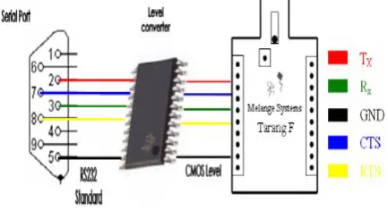
4.9 RS232 Serial Communication
Serial communication is basically the transmission or reception of data one bit at a time. Today's computers generally address data in bytes or some multiple thereof. A byte contains 8 bits. A bit is basically either a logical 1 or zero. Every character on this page is actually expressed internally as one byte. The serial port is used to convert each byte to a stream of ones and zeroes as well as to convert streams of ones and zeroes to bytes. The serial port contains an electronic chip called a Universal Asynchronous Receiver/Transmitter (UART) that actually does the conversion.
Fig13: RS232 Interfacing with the AT89S52
Electrically speaking, whenever the serial port sends a logical one (1) a negative voltage is effected on the transmit pin.
Whenever the serial port sends a logical zero (0) a positive voltage is affected. When no data is being sent, the serial port's transmit pin's voltage is negative (1) and is said to be in a MARK state. Note that the serial port can also be forced to keep the transmit pin at a positive voltage (0) and is said to be
the SPACE or BREAK state. (The
terms MARK and SPACE are also used to simply denote a negative voltage (1) or a positive voltage (0) at the transmit pin respectively).When transmitting a byte, the UART (serial port) first sends a START BIT which is a positive voltage (0), followed by the data (general 8 bits, but could be 5, 6, 7, or 8 bits) followed by one or two STOP BITs which is a negative (1) voltage. The sequence is repeated for each byte sent.
5. ROBOTIC MOVEMENT CONTROL
The control of the robot can select the manual mode and a manual running operation by the function menu. The manual function command like forward, back, right turn, left turn, and stop can be chosen. The control signal is transmitted to PC by the selected command, and the running control of the robot is started. And the robot is fully controlled by the manual mode and the corresponding button creates own effect to the movement of robot [7].6. SOFTWARE DESCRIPTION
The entire software is divided in to three modules and these modules uses different software for particular operation.
1. Videocapx: It is used for the video streaming in the local server. Videocapx is multimedia programming API through which the video is delivered to the server .manly it is used in this project because it supports all types of camera either wired or wireless or web cam.
2. SMS Gateway: It is used when the server fails or the ultrasonic sensors goes out of the range then the gateway invoked the security SMS and deliver to the authorized person with the help of internet
3. Ultrasonic sensors: It is integrated with the user interface whenever the sensor senses the environment the digital value passed to the microcontroller and the controller switches to the user interface and show the output
And for the front end and the back end we are using different software. C# .NET- It effectively integrates the hardware and software.
6.1 Embedded C
Embedded C is a set of language extensions for the c programming language by the C standards committee. It introduces a number of features not available in normal C and basic I/O hardware addressing [8]. It is having the declaration of microcontroller registers and special function as header files, we can include these files to make easy implementation. Embedded C has same flow and programming methodology as C. It has unlimited number of source files, mixed C and assembler programming. It’s Compatibility integrates into the MPLAB IDE, MPLAB ICD and most 3rd-partydevelopment tools and Runs on multiple platforms: Windows, Linux, UNIX, Mac OS X, Solaris EX:- Kiel C.
6.2 Compiler
Compilers are programs used to convert a High Level Language to object code. Desktop compilers produce an output object Start
Video Display
Stop Is Video display
fails? SMS
SMS Gateway with no DND Service No
code for the underlying microprocessor, but not for other microprocessors. That is the programs written in one of the HLL like ‘C’ will compile the code to run on the system for a particular processor like x86 (underlying microprocessor in the computer). For example compilers for Dos platform is different from the Compilers for UNIX platform [9]. So if one wants to define a compiler then compiler is a program that translates source code into object code. The compiler derives its name from the way it works, looking at the entire piece of source code and collecting and reorganizing the instruction. See there is a bit little difference between compiler and an interpreter. Interpreter just interprets whole program at a time while compiler analyzes and execute each line of source code in succession, without looking at the entire program. The advantage of interpreters is that they can execute a program immediately. Secondly programs produced by compilers run much faster than the same programs executed by an interpreter. However compilers require some time before an executable program emerges. Now as compilers translate source code into object code, which is unique for each type of computer, many compilers are available for the same language [10].
[image:7.595.76.273.569.691.2]7. IMPLEMENTATION
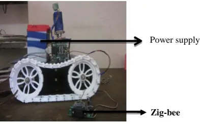
Fig 13: The Prototype of the Proposed System
The prototype of the proposed system is shown in fig 13 and local server gives the details about the movement of obstacles
and intruder that is distance and angle of the obstacles. USB camera senses the environment and sends the video data to the monitoring end. Figure 14 shows the zig-bee receiver which sends the data through the UART to PC (monitoring end). And the zig-bee transmitter transmits the data to the PC.
Fig 14: Zig-Bee Interfaced with the System
Fig15: Design at the Robot side
8. CONCLUSION
Radar based robot successfully detected the intruder and it determines the angle and distance to the obstacle. It also provides the video streaming to the server. The ultrasonic sensor senses the obstacle and gives the idea about the intruder and obstacle. It works efficiently well even in darkness. It also even detects a crawling man at a distance of thirty meters. The system provides the output even in the tangential direction of the radar and also worked well in the presence of dust, smoke and precipitation. In future we plan to extend our work by using good quality IP camera and the robot can be controlled through the web server. And also we can use the multiple ultrasonic sensors so that it can give the exact value and senses the object more clearly.
9. REFERENCES
[1] Bafen chen, System to detect the obstacle in unknown environment, 18th Annual International Conference of the IEEE Engineering in Medicine and Biology Society, Amsterdafd-9 9.6.
[2] Dong-Won Jung, Multi-Channel Ultrasonic Sensor System for Obstacle Detection of the Mobile Robot, International Conference on Control, Automation and Systems 2007.
[3] A.Cherubini, Development of a multimode navigation systemfor an assistive robotics project 2007 IEEE International Conference onRobotics and AutomationRoma, Italy, 10-14 April 2007.
[4] Chidambar Ganesh, Ultrasonic Sensor-based Motion Control for Robotic Manipulators, Automated Systems Laboratory, Department of Engineering, Colorado School of Mines.
[5] Randal Beard, Derek Kingston, Morgan Quigley, Deryl Snyder, Reed Christiansen, Walt Johnson, Timothy McLain, and Michael A. Goodrich, Autonomous vehicle technologies for small fixed-wing UAVs. Journal of Aerospace Computing, Information, and Communication,No.2:92–102, January 2005.
[6] Allen D.Wu, Eric N. Johnson, and Alison A. Proctor, Vision-aided inertial navigation for flight control. Journal Of Aerospace Computing, Information, and Communication, 2(9):348–360, 2005.
[7] E.W. Frew, X. Xiao, S. Spry, T. McGee, Z. Kim, J. Tisdale, R. Sengupta, and J. K. Hendrick. Flight demonstrations of self-directed collaborative navigation of small unmanned aircraft. In AIAA 3rd Unmanned Unlimited Technical Conference, September 2004.
Zig-bee Power supply
RELAY VOLTAGE REGULATO R
CAPACITOR
Local server
USB camera
MICRO CONTROLLER
[8] Ruggero Frezza and Claudio Altafini. Autonomous landing by computer vision: an application of path following in SE(3). In Conference on Decision and Control, December 2004.
[9] Sudesh Kumar Kashyap, Girija G., and J.R. Raol. Evaluation of converted measurement and modified extended Kalman filters for target tracking. In AIAA Guidance, Navigation and Control Conference and Exhibit, August 2003.Jusuk Lee, Rosemary Huang, Andrew Vaughn, Xiao Xiao, and J. Karl Hedrick. Strategies of path-planning for a UAV to track a ground
vehicle. In Proceedings of the 2nd Anual Autonomous Intelligent Networks and Systems Conference, 2003. [10]L. Ma, C. Cao, V. Dobrokhodov, I. Kaminer, K. Jones, and
I. Kitsios. Rapid motion estimation of a target moving with time-varying velocity. In AIAA Guidance, Navigation and Control Conference and Exhibit, August 2007.