© 2018, IRJET | Impact Factor value: 6.171 | ISO 9001:2008 Certified Journal | Page 3011
INTELLIGENT REVERSE BRAKING SYSTEM
Jadhav Amol D.
1, Chavhan Tushar V.
2, Sonawane Ravindra F.
3, Thombre Amol V.
4Asst. Prof. Aher Sandip S.
51,2,3,4
BE Student Mechanical SND COE & RC, Yeola, Maharashtra, India
5Asst.Prof. Mechanical SND COE & RC, Yeola, Maharashtra, India
---***---Abstract -
Currently, vehicles are often equipped with
active safety systems to reduce the risk of accidents, many of which occur in the urban environments. The most popular include Antilock Braking Systems (ABS), Traction Control and Stability Control. All these systems employ different types of sensors to constantly monitor the conditions of the vehicle, and respond in an emergency situation. In this paper the use of ultrasonic sensors in safety systems for controlling the speed of a vehicle is proposed. An intelligent mechatronic system includes an ultrasonic wave emitter provided on the front portion of a car producing and emitting ultrasonic waves frontward in a predetermined distance. An ultrasonic receiver is also placed on the front portion of the car operatively receiving a reflective ultrasonic wave signal. The reflected wave (detected pulse) gives the distance between the obstacle and the vehicle. Then a microcontroller is used to control the speed of the vehicle based on the detection pulse information to push the brake pedal and apply brake to the car stupendously for safety purpose.Reverse accidents are today very prominent with increase in number of vehicles and short attention spans of the users. More over 30% of total accidents in fleet management occurs while reversing. The big sizes of passenger cars like SUVs, trucks and their attachments like trolleys, Caravans, Motorhomes, etc. make these vehicles more prone to reverse accidents and sometimes, these accidents can be vital. In this way we make the system cheaper, universal, easy to install and without interfering with the factory equipment’s and prevent void of warranty. Also no need of need of new master cylinder hence cheaper to develope as a product. Hence the factory safety equipment’s such as ESP and ABS will remain unaffected too.
Key Words: IR sensor, Pneumatic braking, Automation,
Ultrasonic sensor.
1. INTRODUCTION
An intelligent reverse braking system is compiled with IR sensor circuit which operates a pneumatic braking system. The main target for this project is cars can run reverse automatic braking due to obstacles when the sensor senses the obstacles. The braking circuit function is to brake the car automatically after received signal from the sensor. This mainly concern in replacement of human effort by the mechanical braking. So it is the best safety feature for the vehicles.
The pneumatically braking system stops the vehicle in 2 to 3 seconds when speed running speed is of 50 Km and the distance of stopping the vehicle is 1.6m. The Intelligent braking system is fully automated. To allow the driver to park the vehicle in tight place, it has parking mode system. In this mode sensor sensing length is reduced to 40cm distance. Degrees of automation are two types:
Semi Automation Full Automation
The semi automation is manual efforts with mechanical power whereas in full automation manual participation in the work is very negligible. Intelligent automatic reverse braking is of full automation type automation.
2. LITERATURE REVIEW
The existing approaches in preventing accidents are: Honda’s idea of ABS (Anti-lock Braking System) which helps the rider get a hassle free braking experience in muddy and watery surfaces by applying a distributed braking and prevents skidding and wheel locking.
Volvo is all set to launch its new XC60 SUV which will sport laser assisted braking which will be capable to sense a collision up to 50 mph and apply brakes automatically.
Drawbacks in the existing approaches:
• ABS can only help if the rider applies it in the right time manually and maintains the distance calculations. ABS has its own braking distance.
• Moreover many commuter bikes in India don’t have the option of ABS because it’s very expensive.
• Volvo’s laser assisted braking could not work effectively in rainfall and snowfall season and laser is easily affected by atmospheric conditions.
© 2018, IRJET | Impact Factor value: 6.171 | ISO 9001:2008 Certified Journal | Page 3012
3. PRINCIPAL COMPONENTS OF ULTRASONIC
SENSOR
Ultrasonic ranging and detecting devices make use of high-frequency sound waves to detect the presence of an object and its range.
These systems either measure the echo reflection of the sound waves from objects or detect the interruption of the sound beam as the objects pass between the transmitter and receiver.
An ultrasonic sensor typically utilizes a transducer that produces an electrical output pulse in response to the received ultrasonic energy.
The normal frequency range for hearing of humans is roughly around 20 to 20,000 hertz. Ultrasonic sound waves are the sound waves that are above the range of human hearing capability and, so have a frequency above 20,000 hertz. Any frequency which is above 20,000 hertz may be considered as ultrasonic. Most of the industrial processes, including almost all the sources of friction, create some ultrasonic noise. The ultrasonic transducer produces ultrasonic signals. These signals propagate through a sensing medium and the same transducer can be used to detect the returning signals. Ultrasonic sensors usually have a piezoelectric ceramic transducer that converts an excitation electrical signal into ultrasonic energy bursts. This energy bursts travel from the ultrasonic sensor, bounce off objects, and are returned towards the sensor as echoes. Transducers are the devices that convert electrical energy to mechanical energy, or vice versa. The transducer converts the received echoes into analog electrical signals that are outputs from the transducer.
The piezoelectric effect refers to the voltage produced between surfaces of a solid dielectric (no conducting substance) when some mechanical stress is applied to it. On the other hand when a voltage is applied across certain surfaces of a solid that exhibits the piezoelectric effect, the solid undergoes a mechanical distortion. Such type of solids typically resonates within narrow frequency ranges. Piezoelectric materials are generally used in transducers. For example, they are used in phonograph cartridges, strain gauges, and microphones that produce an electrical output from a mechanical input. Also, they are used in earphones and ultrasonic transmitters that produce a mechanical output from an electrical input.
Ultrasonic transducers operate to radiate ultrasonic waves through a medium such as air. Transducers generally create ultrasonic vibrations with the use of piezoelectric materials such as certain forms of crystal or ceramic polymers.
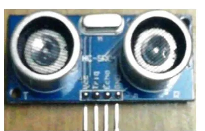
[image:2.595.331.539.72.205.2]
Fig: 2.1.Ultrasonic sensor
4. OPERATING PRINCIPLE:
This application is based upon the reflection of sound waves. Sound waves are defined as longitudinal pressure waves in the medium in which they are travelling. Subjects whose dimensions are larger than the wavelength of the impinging sound waves reflect them; the reflected waves are called the echo. If the speed of sound in the medium is known and the time taken for the sound waves to travel the distance from the source to the subject and back to the source is measured, the distance from the source to the subject can be computed accurately. This is the measurement principle of this application. Here the medium for the sound waves is air, and the sound waves used are ultrasonic, since it is inaudible to humans.
Assuming that the speed of sound in air is 1100 feet/second at room temperature and that the measured time taken for the sound waves to travel the distance from the source to the subject and back to the source is t seconds, the distance d is computed by the formula d=1100 X 12 X t inches. Since the sound waves travel twice the distance between the source and the subject, the actual distance between the source and the subject will be d/2.
DISTANCE MEASUREMENT METHODS:
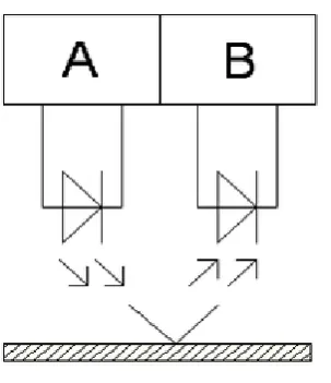
1. IR SENSOR:
IR distance sensors are one of the most used distance sensors. They fall in 3 categories:
Reflection (Short range. Not more than 2 - 3cm)
© 2018, IRJET | Impact Factor value: 6.171 | ISO 9001:2008 Certified Journal | Page 3013 Fig -1: IR reflection sensor
Triangulation
(Larger range Around 10 - 30cm) e.g. sharp has a family of sensors that use this principle for measuring distance. They consist of an IR-LED and an IR-sensitive LDR strip. Combined with built-in optical lenses, the reflected beam's position on the LDR depends on how far the object is.
2. ULTRASONIC SENSOR:
Ultrasonic distance sensors use sound to measure distance. These sensors emit an ultrasonic pulse train and then measure the time until the pulse is reflected. Since the speed of sound is (more or less; excluding temperature and wind) constant in air (approx. 344m/s) it is easy to calculate the distance to the reflecting object. These are used for distance ranging from several centimeters up to a few meters.
3. PROXIMITY SENSOR:
A proximity sensor is a sensor able to detect the presence of nearby objects without any physical contact. A proximity sensor often emits an electromagnetic field or a beam of electromagnetic radiation (infrared, for instance), and looks for changes in the field or return signal. The object being sensed is often referred to as the proximity sensor's target. Different proximity sensor targets demand different sensors. For example, a capacitive or photoelectric sensor might be suitable for a plastic target; an inductive proximity sensor always requires a metal target. The maximum distance that this sensor can detect is defined "nominal range". Some sensors have adjustments of the nominal range or means to report a graduated detection distance. Proximity sensors can have a high reliability and long functional life because of the absence of mechanical parts and lack of physical contact between sensor and the sensed object.
Proximity sensors are commonly used on smartphones to detect (and skip) accidental touchscreen taps when held to the ear during a call. They are also used in machine vibration
monitoring to measure the variation in distance between a shaft and its support bearing. This is common in large steam turbines, compressors, and motors that use sleeve-type bearings.
CALCULATIONS
1.1 FRAME DESIGN:
Material used –mild steel, square pipe Area=1*1inch=25.4*25.4=645.6mm2
Length of link=30 inch=762 mm
Weight of project=15 kg= 15*9.81 =147.15 N
SOLUTION
1.1.1 Effective length
Effective length, when both end fixed,
Le=
L
2
=762
2
=381 mm1.1.2 Internal Area
Internal width and depth, which have 3 mm thickness, d=b=38.1- (2*3) =32.1 mm
1.1.3 Moment of inertia
I=
B D
3−
b d
312
=25.4 =22882.048mm41.1.4 Crippling load by Euler’s formula
Pc=
π
2EI
L e
2 = =326.711kN1.2 BRAKE CALCULATION:
Brake drum (Front) = 110 mm Brake Drum (Rear) = 110 mm
This brake is Internally Expanding brake. Radius of drum = R = 55 mm
Face Width = b = 30 mm h = R-(b/2)
= 55- (30/2) = 40 mm
Length between pivot and spring = L = 90 mm Assuming
© 2018, IRJET | Impact Factor value: 6.171 | ISO 9001:2008 Certified Journal | Page 3014 1.2.1 FOR LEADING SHOE
1.2.1.1 MNL
= *{2(
θ
2
−
θ
1
)-(sin
2
θ
2
−
sinθ
1
)}= *{2(1.57079
−
0
)-(sin180
−
sin 0
)}= 4950*(3.14158-0) =15550.821 N-mm
1.2.1.2 MFL
= {4R (cos
θ
1
- cosθ
2
)-h (cos2
θ
1
-cos
2
θ
2
)}= {4* 55 (cos
0
- cos 90) – 40 (cos0
- cos180
)}= 49.5*(180*1-70) = 6930 N-mm
1.2.1.3 Actuating Force
F*L = MNL - MFL
F =
MFL
−
L
MNL
F =
15550.821
90
−
6930
F= 93.7859 N1.2.1.4 Braking Torque
=
=
= 10890 N-mm =10.89 N-m
1.2.2 FOR TRAILING SHOE 1.2.2.1 MNT
= *{2(
θ
2
−
θ
1
)-(sin2
θ
2
−
sinθ
1
)}= {2(1.57079
−
0
)-(sin180
−
sin 0
)}= Pmax*16500*(3.15158-0) =Pmax*51836.07 N-mm
1.2.2.2 MFT
= {4R*
} = {4* 45 (cos
0
- cos 90) – 35 (cos0
- cos180
)}= Pmax*165*140 = 23100*Pmax N-mm
1.2.2.3 Actuating Force
F*L = MNT + MFT
F =
MFT
+
L
MNT
95.7869 =
Pmax = 0.115 N/mm2
1.2.2.4 Braking Torque
=
=
= 4174 .56 N-mm = 4.1745 N-m
1.2.2.5 Total Braking Torque Capacity
Tb= TbL + TbT
= 10.89+4.1745 = 15.0645 N-m
1.2.3 DOUBLE ACTING PNEUMATIC CYLINDER Given data:
Cylinder: 20*50
1.2.3.1 Volume of air exhaust =Stroke *Area of piston
=100*π/4*20^2 =31415.92 m^3
© 2018, IRJET | Impact Factor value: 6.171 | ISO 9001:2008 Certified Journal | Page 3015 1.2.3.3 Outstroke force (F) = Pressure *Area of
cylinder =0.4*314.15 =125.66 N
1.2.3.4 Piston rod area (A1) = π/4*d^2 = π/4*7^2
=38.48mm^2
1.2.3.5 Effective area= Piston area- Piston rod area =314.15-38.48
=275.66 mm^2
1.2.3.6 Instroke force= P*A =0.4*275.66
=110.26 N
ADVANTAGES
Saves expense spend on reverse accidents in fleet managements.
Allows trucks, mini trucks to tow bigger trollies in reverse without external helping person to navigate.
Makes passenger car safer in parking, accidents and other reverse accidents
.
APPLICATIONS
Passenger cars Car vans Trollies Trailers
Fleet managements
CONCLUSION
In the present work, a prototype of an ultrasonic distance measurement for stationary obstacle is obtained. And controlling the speed of vehicle accordingly to predetermined distance is shown. An ultrasonic sensor, cheaper and less demanding of hardware than other types of sensors presently used, such as the sensors based on computer vision or radar , is used to measure the distance between vehicle and the obstacle. The relative speed of the vehicle with respect to the obstacle is estimated using consecutive samples of the distance calculated. These two quantities are used by the control system to calculate the actions on both the accelerator and also the brake, thus to adjust the speed in order to maintain a safe distance to prevent accidents. As ultrasonic sensors can detect any kind of obstacle, this system can also prevent collision of the vehicle with pedestrians, or can at least reduce the injuries occurring.
Since the control system does not use the absolute speed to calculate the safety distance as done by the currently existing
systems, the interaction with automotive electronics is limited to actions on the accelerator and brake. This matter, coupled with the fact of lower cost of ultrasonic sensors compared with other kinds of sensors, could facilitate the application and mounting of the system in many low-end vehicles, helping to improve comfort and safety and offer a hassle free driving experience at a reduced cost.
REFERENCES
[1] Wikipedia, the Free Encyclopedia- Anti-lock braking system for motorcycle,
http://en.wikipedia.org/wiki/Anti-lock_braking_system_for_motorcycles, September 08, 2014.
[2] Autotrader.com,
http://www.autotrader.com/research/article/car- news/210852/new-automatic-parking-system-will-reach-volvo-models.jsp, October 12, 2014.
[3] Thiess Field Trials- Reverse Alert Technology, Automatic Braking System, Reverse Alert Australia, PP 1-12, 2013.
[4] G.V. Sairam, B. Suresh, CH. Sai Hemanth and K. Krishna Sai, “Intelligent Mechatronics Braking System”, PP 100-102, 2013
BIOGRAPHIES
Amol Dattatray Jadhav SND COE & RC, YEOLA BE-Mechanical
Tushar Vinayak Chavhan SND COE & RC, YEOLA BE-Mechanical
Ravindra Fakira Sonawane SND COE & RC, YEOLA BE-Mechanical
Amol Vilas Thombre SND COE & RC, YEOLA BE-Mechanical