Buckling Studies on Laminated Composite Skew Plates
C.V. Srinivasa
Department of Mechanical Engineering
GM Institute of Technology, Davangere-577006, India
Y.J. Suresh
Department of Mechanical Engineering
J.N.N. College of Engineering Shivamogga-577204, India
W.P. Prema Kumar
Department of Civil Engineering Nagarjuna College of Engineering & Technology
Bangalore-562110, India
ABSTRACT
This paper presents buckling studies made on skew plates using finite element. The effects of the skew angle, aspect ratio, length-to-thickness-ratio, fibre orientation angle, and numbers of layers in the laminate and laminate sequence on the critical buckling load factor (Kcr) of antisymmetric composite laminates have also been presented. The critical buckling load factor (Kcr) is found to increase with the skew angle. When the number of layers in the laminate is large, the variation of critical buckling load factor (Kcr) with the number of layers is not appreciable.
Keywords
Skew Plates; Antisymmetric Laminates; Buckling; Finite Element,
Nomenclature:
a : Plate length
b : Plate width
t : Plate thickness
NL : Number of layers
E : Modulus of elasticity
1
E : Young’s modulus of the fibre in longitudinal
direction
2
E : Young’s modulus of the fibre in transverse
direction
12
G : Shear modulus
D : Plate bending rigidity, 3 2 / 12(1 )
Et
r
k : Ratio of buckling factors
cr
K : Buckling load intensity factor
: Skew angle
: Fibre orientation angle
: Poisson’s ratio
12
: Major Poisson’s ratio
: Eigen Value
x
N : Stress along x-axis
x
: In-plane stress along x-axis
1. INTRODUCTION
Due to light weight and high strength, the use of fibre-reinforced composite materials has increased rapidly in recent years. Application fields of composite materials are continuously expanding from traditional application areas such as military aircraft to various engineering fields such as automobiles, robotics, day to day appliances, building industry etc. The design of components made of such materials demands correct understanding of the structural behavior such as deflections, buckling loads and modal characteristics, the through-thickness distributions of stresses and strains etc including failure characteristics. The members
and structures composed of laminated composite materials are usually very thin and hence more prone to buckling. Their buckling must be accounted for in the safe and reliable design of composite structures among other considerations.
The skew plates are often used in civil, marine, aeronautical and mechanical engineering applications. Complex alignment problems in bridge design arising from functional, aesthetic or structural requirements are often solved by the use of skew plates. Various other applications of skew plates can be found in ship hulls, swept wings of aero planes, parallelogram slabs in buildings etc.
Few analytical solutions are available for skew plates and that too for simple cases. When the analytical methods[1-13] have failed to provide solutions, the numerical techniques such as finite element[14-33], finite-strip element method [34], spline finite strip-method[35-36] and differential quadrature methods[37-40] have been employed successfully for the analysis of skew plates. Studies on skew composite plates available in literature are not many.
This paper deals with the determination of critical buckling load factors for isotropic and laminated composite skew plates using CQUAD4 and CQUAD8 elements of MSC/NASTRAN. The accuracy of the elements has been verified against literature values. The effects of skew angle, fibre orientation angle, number of layers in the laminate, laminate sequence and boundary conditions on the critical buckling load factor (Kcr)of skew plate are investigated.
2.
VALIDATION AND CONVERGENCE
STUDIES
In the present work classical buckling analysis is performed on isotropic and laminated skew composite plates by using MSC/NASTRAN software. CQUAD4 (four-noded plate element) and CQUAD8 (eight-noded isoparametric curved shell element) are employed in the present investigation. Numerical studies are carried out on isotropic and laminated composite skew plates with clamped/simply supported edge conditions.
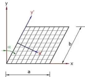
Figure 1: Geometry of the skew plate with finite element mesh showing global and local coordinate systems.
2.1 Validation check
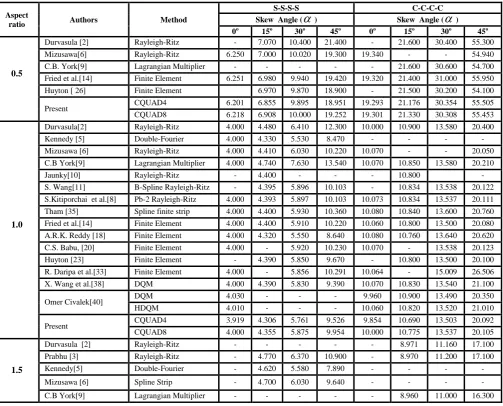
The validation for the present elements is performed by comparing the values for critical buckling load intensity factor (Kcr)obtained in this work with those available in literature. The same is presented in Table 1 for simply supported(S-S-S-S) and clamped(C-C-C-C) isotropic skew plates. It can be seen from Table 1 that the results obtained using the CQUAD8 element are closer to the literature values than the results obtained using CQUAD4 element.
In a similar manner validation check is performed considering a simply supported square antisymmetric high modulus graphite/epoxy angle-ply laminates with different fibre angle (0o to 90o) and different number of layers while keeping the total thickness constant.
The results obtained in the present work are presented in Table 2 and compared with the results available in [41]. It is observed that there is a good agreement. From Table 2 it can be seen that CQUAD8 element yields better results when compared with the CQUAD4 element. Hence CQUAD8 element is employed in the further studies of the present work.
2.2 Convergence study
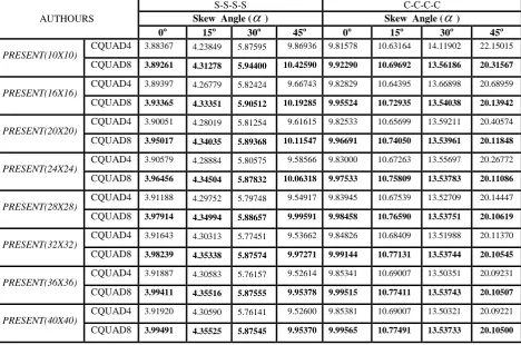
Convergence study has been undertaken to establish the number of elements required for ensuring adequate accuracy. This study has been performed on simply supported(S-S-S-S) and clamped(C-C-C-C) isotropic skew plates having aspect ratio (=a/b) of 1.0 and skew angles 0o,15o, 30o and 45o using CQUAD4 (four-noded) and CQUAD8 (eight-noded isoparametric curved shell element) elements of MSC / NASTRAN. The convergence details are presented in Table 3.
3
.
PRESENT WORK – RESULTS AND
DISCUSSIONS
The present work has been carried by using CSQUAD8 element of MSC/NASTRAN and based on classical buckling analysis. The material properties used are:
/
40 , G /
0.5 and
0.25
l t lt t lt
E
E
E
.The results of the present work are presented in the form of buckling load intensity factor (Kcr)as:
2
for isotropic and 2
2
for laminated skew plates
2 3
2
b t K
cr x D
N b x K
cr E t
3.1 Isotropic skew plates
Studies have been made on skew plates with different aspect ratios, skew angles, and length-thickness ratio with simply supported and clamped boundary conditions. The results obtained are tabulated in Table 4 in the form of buckling load intensity factor (Kcr).
Form table 4, it is seen that Kcr decreases as the aspect ratio (a/b) increases in the case of C-C-C-C boundary condition. For the S-S-S-S boundary condition, Kcr decreases as the aspect ratio increases up to 1.0 and thereafter the change is not considerable. It is also seen that as the skew angle (α) increases the Kcr also increases for constant values of a/b and a/t.
3.2 Laminated skew plates
The lamination sequences considered in the present work are: (1) antisymmetric cross-ply and (2) antisymmetric angle-ply. In both the cases the results are presented for graphite epoxy composite plates with material properties:
206.91 , 5.173 , 2.586 , and 0.25
1 2 12 12
E GPa E GPa G GPa
The results are presented in terms of non-dimensional critical buckling load factor (Kcr).
3.2.1 Antisymmetric cross-ply skew laminates
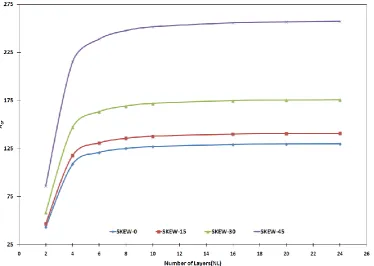
The variation of critical buckling load factor (Kcr)with respect to skew angle(α), fibre orientation angle (θ) and number of layers(NL) for graphite/epoxy antisymmetric cross-ply skew laminates are presented in Figs. 2 and 3 for simply supported and clamped boundary conditions respectively. From Figs. 3 and 4 it is seen that, as the skew angle increases Kcr increases for a given number of layers. For a given skew angle, it is also seen that Kcr increases initially up to NL = 4 and remains constant thereafter irrespective of the skew angle.
3.2.2 Antisymmetric angle-ply skew laminates
a) Simply supported boundary condition
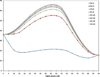
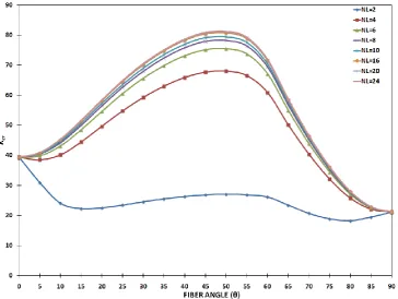
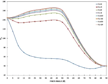
The variations of buckling load intensity factor (Kcr) with skew angle (α), fibre orientation angle (θ) and number of layers (NL) for antisymmetric angle-ply skew laminates under S-S-S-S boundary conditions are presented in Figs. 4-7. For NL=2, Kcr initially decreases with fibre orientation angle and later varies as shown in Figures 4-7. For NL≥4 and for all the skew angles, Kcr increases and reaches a maximum at about θ=57.5o
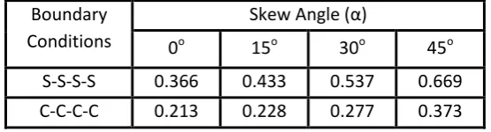
,47o,48o and 50o, for skew angles = 0o,15o,30o and 45orespectively. The increase in Kcr beyond NL= 10 is not appreciable in all the cases. The ratio of buckling factors Kr is defined asKr
Kcr 900/
Kcr 00. The values of r
K for various skew angles are presented in Table 5. It is seen that Kr decreases as the skew angle increases. b) Clamped Boundary Condition
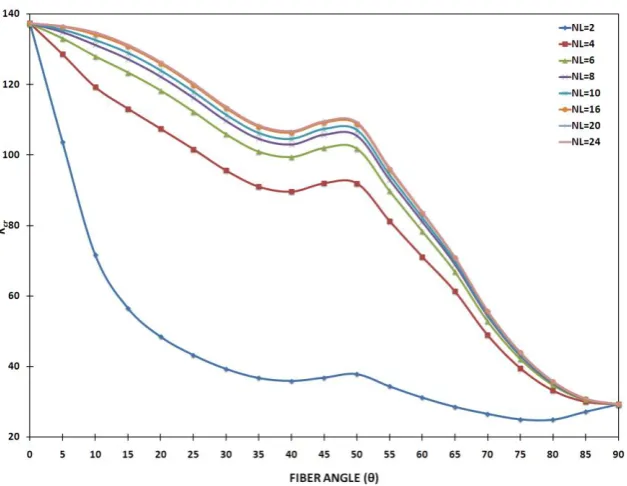
Anti-symmetric Angle-Ply laminated skew plates with simply supported and clamped edge conditions. The Kr values for various skew angles (α) are presented in Table 5.
4. CONCLUSIONS
The present investigation deals with buckling of composite skew plates, the parameters considered being skew angle, aspect ratio, lamination sequence, fibre orientation angle, number of layers and boundary conditions. It is seen that CQUAD8 element of MSC/NASTRAN yields better results when compared with CQUAD4 element. The said elements have been validated against literature values. It is seen that the buckling load of a skew plate increases as the skew angle increases. The buckling load also increases with the increase in number of layers in the laminate keeping total thickness constant up to about 10 layers, beyond which the increase is not substantial. The boundary condition has a significant effect on the buckling load.
5. ACKNOWLEDGMENTS
The first author would like to thank the Management and Principal of GM Institute of Technology, Davangere, Karnataka, India for the kind encouragement and constant support provided. The second author would like to thank the Management of Jawaharlal Nehru College of Engineering, Shivamogga, India for the kind encouragement and support provided. The third author wishes to thank the Management and Principal of Nagarjuna College of Engineering & Technology, Bangalore for the kind encouragement and support provided.
6. REFERENCES
1. Asthon, J.E.1969. Stability of clamped skew plates under combined loads. Journal of Applied Mechanics. 139-140. 2. Durvasula, S.1970. Buckling of clamped skew plates.
AIAA Journal. 8(1).178-181.
3. Prabhu, M.S.S., and Durvasula, S. 1972. Stability of clamped skew plates. Applied Science research. 26. 255-271.
4. Srinivasan, R.S., and Ramachandran, S.V. 1976. Stability of generally orthotropic skew plate. Journal of the Engineering Mechanics Division. 102(EM3). 569-572. 5. Kennedy, J.B., and Prabhakara, M.K. 1978. Buckling of
simply supported orthotropic skew plates. Aeronautical Quarterly. 161-174.
6. Mizusawa, T., Kajita, T., and Naruoka, M. 1980. Buckling of skew plates structures using B-spline functions. International Journal for Numerical Methods in Engineering.15. 87-96.
7. Kamal, K., and Durvasula, S. 1991. A continuum solution to the problems of composite laminate analysis. Defense Science Journal. 41(1). 69-77.
8. Kitipornchai, S., Xiang, Y., Wang, C.M., and Liew, K.M. 1993. Buckling of thick skew plates. International Journal for Numerical Methods in Engineering. 36.1299-1310.
9. York, C.B., and Williams, F.W. 1995. Buckling analysis of skew plate assemblies: Classical plate theory results incorporating lagrangian multipliers. Computers and Structures. 56(4).625-635.
10. Jaunky, N., Norman, F. Knight Jr., and Ambur, D.R. 1995. Buckling of arbitrary quadrilateral anisotropic plates. AIAA Journal. 2414-2417.
11. Wang, S. 1997. Buckling of thin skew fibre-reinforced composite laminates. Thin Walled Structures. 28(1).21-41.
12. Azhari, M., Shahidi, A.R., and Saadatpour, M.M. 2004. Post local buckling of skew and trapezoidal plates” Advances in Structural Engineering. 7(1).61-70.
13. Pannok, C., and Singhatanadgid, P. 2006. Buckling analysis of composite laminate rectangular and skew plates with various edge support conditions. The 20th Conference of Mechanical Engineering Network of Thailand .18-20.
14. Fried, I., and Schmitt, K. 1972. Numerical results from the application of gradient iterative techniques to the finite element vibration and stability analysis of skew plates. Aeronautical Journal. 76. 166–169.
15. Bucco, D., and Mazumdar, J. 1984. Buckling analysis of plates of arbitrary shape. Journal of Australian mathematical society. Serial B26. 77-91.
16. Lee, Y.J., Lin, H.J, and Lin, C.C. 1989. Buckling analysis of composite laminates. Composite Structures. 12.133-148.
17. Liao, C.L., and Lee, Z.Y. 1993. Elastic stability of skew laminated composite plates subjected to biaxial follower forces. International Journal for Numerical Methods in Engineering. 36. 1825-1847.
18. Krishna Reddy, A.R., and Palaninathan, R. 1995. Buckling of laminated skew plates. Thin Walled Structures. 22 .241-259.
19. Wang, S. 1997. Buckling analysis of skew fibre-reinforced composite laminates based on first-order shear deformation theory” Composite Structures. 37(1).5-19. 20. Sarath Babu, C., and Kant, T. 1999. Two shear
deformable finite element models for buckling analysis of skew fibre-reinforced composite and sandwich panels. Composite Structures. 46(2).115-124.
21. Hu, H.T., and Tzeng, W.L. 2000. Buckling analysis of skew laminate plates subjected to uniaxial inplane loads. Thin-Walled Structures. 38. 53-77.
22. Kant, T. and Babu, C.S. 2000. Thermal buckling analysis of skew fibre-reinforced composite and sandwich plates using shear deformable finite element models. Composite Structures.49. 77-85.
23. Huyton, P., and York, C.B. 2001. Buckling of skew plates with continuity or rotational edge restraint. Journal of Aerospace Engineering. 92-101.
24. Singha, M.K, Ramachandra, L.S., and Bandyopadhyay, J.N. 2001. Thermal post buckling analysis of laminated composite plates. Composite Structures.54. 453-458. 25. Singha, M.K., Ramachandra L.S., and Bandyopadhyay,
J.N. 2001. Stability and strength of composite skew plates under thermo mechanical loads. AIAA Journal. 39(8). 1618-1623.
26. Huyton, P., and York, C.B. 2002. Buckling of skew plates with planform taper. AIAA Journal. 1572-1581. 27. Ganapathi, M., Prakash, T., and Sundararajan, N. 2006.
28. Hsuan-The, Hu. Chia-Hao Yang, and Fu-Ming Lin. 2006. Buckling analyses of composite skew plates with material nonlinearity. Composites: Part B.37. 26-36. 29. Partha, Dey, and Singha, M.K. 2006. Dynamic stability
analysis of composite skew plates subjected to periodic in-plane load. Thin-walled structures. 44.937-942. 30. Chakrabarti, A., and Sheikh, A.H. 2007. Buckling of
laminated sandwich plates using an efficient plate model. International Shipbuilding Progress. 54.63-81.
31. Prakash, T., Singha, M.K., and Ganapathi, M. 2008. Thermal post buckling analyses of FGM skew plates. Engineering Structures. 30. 22–32.
32. Civalek, O. 2007. Free vibration and buckling analyses of composite plates with straight-sided quadrilateral domain based on DSC approach. Finite Elements in Analysis and Design. 43.1013-1022.
33. Rupesh, D., and Singha, M.K. 2009. Influence of corner stresses on the stability characteristics of composite skew plates. International Journal of Non-Linear Mechanics. 44. 138- 146.
34. Thangam Babu, P.V., and Reddy, D.V. 1978. Stability analysis of skew orthotropic plates by the finite strip method. Computers and Structures. 8. 599-607.
35. Tham, L.G., and Szeto, H.Y. 1990. Buckling analysis of arbitrarily shaped plates by spline finite strip method. Computers and Structures. 36(4).729-735.
36. Mizusawa, T., and Kajita, T. 1986. Vibration and buckling analysis of skew plates with edges elastically restrained against rotation. Computers and Structures. 22(6).987-994.
37. Darvizeh, M., Darvizeh, A, and Sharma, C.B. 2002. Buckling analysis of composite plate using differential quadrature method. Steel and Composite Structures. 2(2). 99-122.
38. Wang, X., Tan, M., and Zhou, Y. 2003. Buckling analyses of anisotropic plates and isotropic skew plates by the new version differential quadrature method. Thin-Walled Structures. 41. 15-29.
39. Karami, G., Ali Shahpari, S., and Malekzadeh, P. 2003. DQM analysis of skewed and trapezoidal laminated plates. Composite Structures.59.393-402.
40. Civalek, O. 2004. Application of differential quadrature (DQ) and harmonic differential quadrature (HDQ) for buckling analysis of thin isotropic plates and elastic columns. Engineering Structures.26. 171–186.
[image:4.595.49.553.363.769.2]41. Jones, R.M. 1975. Mechanics of Composite Materials. New York: McGraw-Hill.
Table 1: Buckling load factor (Kcr) for isotropic skew plates (a/b=1, a/t =100)
Aspect
ratio Authors Method
S-S-S-S C-C-C-C
Skew Angle (
) Skew Angle (
)0o 15o 30o 45o 0o 15o 30o 45o
0.5
Durvasula [2] Rayleigh-Ritz - 7.070 10.400 21.400 - 21.600 30.400 55.300 Mizusawa[6] Rayleigh-Ritz 6.250 7.000 10.020 19.300 19.340 - - 54.940 C.B. York[9] Lagrangian Multiplier - - - 21.600 30.600 54.700 Fried et al.[14] Finite Element 6.251 6.980 9.940 19.420 19.320 21.400 31.000 55.950 Huyton [ 26] Finite Element 6.970 9.870 18.900 - 21.500 30.200 54.100
Present CQUAD4 6.201 6.855 9.895 18.951 19.293 21.176 30.354 55.505 CQUAD8 6.218 6.908 10.000 19.252 19.301 21.330 30.308 55.453
1.0
Durvasula[2] Rayleigh-Ritz 4.000 4.480 6.410 12.300 10.000 10.900 13.580 20.400
Kennedy [5] Double-Fourier 4.000 4.330 5.530 8.470 - - - -
Mizusawa [6] Rayleigh-Ritz 4.000 4.410 6.030 10.220 10.070 - - 20.050 C.B York[9] Lagrangian Multiplier 4.000 4.740 7.630 13.540 10.070 10.850 13.580 20.210
Jaunky[10] Rayleigh-Ritz - 4.400 - - - 10.800 -
S. Wang[11] B-Spline Rayleigh-Ritz - 4.395 5.896 10.103 - 10.834 13.538 20.122 S.Kitiporchai et al.[8] Pb-2 Rayleigh-Ritz 4.000 4.393 5.897 10.103 10.073 10.834 13.537 20.111 Tham [35] Spline finite strip 4.000 4.400 5.930 10.360 10.080 10.840 13.600 20.760 Fried et al.[14] Finite Element 4.000 4.400 5.910 10.220 10.060 10.800 13.500 20.080 A.R.K. Reddy [18] Finite Element 4.000 4.320 5.550 8.640 10.080 10.760 13.640 20.620 C.S. Babu, [20] Finite Element 4.000 - 5.920 10.230 10.070 - 13.538 20.123 Huyton [23] Finite Element - 4.390 5.850 9.670 - 10.800 13.500 20.100 R. Daripa et al.[33] Finite Element 4.000 - 5.856 10.291 10.064 - 15.009 26.506 X. Wang et al.[38] DQM 4.000 4.390 5.830 9.390 10.070 10.830 13.540 21.100
Omer Civalek[40] DQM 4.030 - - - 9.960 10.900 13.490 20.350
HDQM 4.010 - - - 10.060 10.820 13.520 21.010
Present CQUAD4 3.919 4.306 5.761 9.526 9.854 10.690 13.503 20.092 CQUAD8 4.000 4.355 5.875 9.954 10.000 10.775 13.537 20.105
1.5
Durvasula [2] Rayleigh-Ritz - - - 8.971 11.160 17.100
Prabhu [3] Rayleigh-Ritz - 4.770 6.370 10.900 - 8.970 11.200 17.100
Kennedy[5] Double-Fourier - 4.620 5.580 7.890 - - - -
Mizusawa [6] Spline Strip - 4.700 6.030 9.640 - - - -
Fried et al.[10] Finite Element - 4.680 4.770 12.300 - 8.910 11.000 16.300 Huyton [26] Finite Element - 4.680 5.890 8.950 - 8.930 11.000 16.200
Present CQUAD4 4.256 4.640 5.955 9.076 8.217 8.887 11.175 16.498 CQUAD8 4.270 4.648 5.865 9.139 8.237 8.897 11.074 16.340
2.0
Prabhu [3] Rayleigh-Ritz - 4.330 6.030 10.300 - 8.700 10.500 15.700
Kennedy [5] Double-Fourier - 4.270 5.200 7.680 - - - -
Mizusawa [6] Spline Strip Method - 4.360 5.730 9.340 - - - -
C.B York[9] Lagrangian Multiplier - - - 8.410 10.300 15.200
Huyton [26] Finite Element - 4.340 5.590 8.800 - 8.390 10.300 15.100
Present CQUAD4 3.885 4.271 5.596 8.855 7.683 8.327 10.326 15.350 CQUAD8 3.903 4.313 5.605 8.871 7.693 8.373 10.292 15.200
[image:5.595.83.517.264.434.2]2.5 Present CQUAD4 4.000 4.410 5.542 8.541 7.273 8.101 9.992 15.016 CQUAD8 4.007 4.418 5.543 8.498 7.290 8.109 9.954 14.763
Table 2: Buckling load factor (Kcr) for simply supported square antisymmetric angle-ply laminates
Fibre Angle (θ)
Number of Layers(NL)=2 Number of Layers(NL)=4 Number of Layers(NL)=6
Jones [41]
Present Jones [41]
Present Jones [41]
Present
CQUAD8 CQUAD4 CQUAD8 CQUAD4 CQUAD8 CQUAD4
0o 35.830 35.794 36.278 35.830 35.794 36.278 35.830 35.794 36.278
15o 21.730 21.244 18.813 38.250 38.212 37.077 41.310 41.260 40.440
30o 20.440 20.282 17.963 49.820 49.745 44.794 55.270 54.873 49.741
45o 21.710 21.307 19.459 56.088 55.369 50.110 62.460 61.229 55.766
60o 19.390 19.026 18.309 45.434 44.632 42.816 50.257 50.108 47.330
75o 14.750 14.230 11.864 22.075 21.834 21.684 23.772 23.592 23.495
[image:5.595.65.534.458.768.2]90o 13.132 13.120 13.304 13.132 13.120 13.304 13.132 13.120 13.304
Table 3: Convergence study for critical buckling load factor (Kcr) for isotropic skew plates (a/b=1, a/t =100)
AUTHOURS
S-S-S-S C-C-C-C
Skew Angle (
) Skew Angle (
)0o 15o 30o 45o 0o 15o 30o 45o
PRESENT(10X10) CQUAD4
3.88367 4.23849 5.87595 9.86936 9.81578 10.63164 14.11902 22.15015
CQUAD8 3.89261 4.31278 5.94400 10.42590 9.92290 10.69692 13.56186 20.31567
PRESENT(16X16)
CQUAD4 3.89397 4.26779 5.82424 9.66743 9.82829 10.64395 13.66898 20.68959
CQUAD8 3.93365 4.33351 5.90512 10.19285 9.95524 10.72935 13.54038 20.13942
PRESENT(20X20)
CQUAD4 3.90051 4.28019 5.81254 9.61615 9.82533 10.65699 13.59211 20.40574
CQUAD8 3.95017 4.34035 5.89368 10.11547 9.96691 10.74050 13.53961 20.11848
PRESENT(24X24)
CQUAD4 3.90579 4.28884 5.80575 9.58566 9.83000 10.67263 13.55697 20.26772
CQUAD8 3.96456 4.34504 5.87832 10.06318 9.97533 10.75809 13.53783 20.11086
PRESENT(28X28)
CQUAD4 3.91188 4.29752 5.79748 9.54917 9.83945 10.67539 13.52709 20.14447
CQUAD8 3.97914 4.34994 5.88657 9.99591 9.98458 10.76590 13.53751 20.10619
PRESENT(32X32)
CQUAD4 3.91643 4.30313 5.77451 9.53662 9.84826 10.68409 13.51988 20.11370
CQUAD8 3.98239 4.35338 5.87574 9.97271 9.99144 10.77131 13.53744 20.10545
PRESENT(36X36)
CQUAD4 3.91887 4.30583 5.76157 9.52614 9.85341 10.69007 13.50351 20.09231
CQUAD8 3.99411 4.35516 5.87555 9.95378 9.99515 10.77411 13.53743 20.10507
PRESENT(40X40)
CQUAD4 3.91920 4.30590 5.76141 9.52600 9.85381 10.69007 13.50321 20.09221
Table 4: Buckling load factor (Kcr) for simply supported and clamped isotropic skew plates
a/b
a/t
Critical Buckling Load Factor (
K
cr)
Skew Angle(α)
0
o15
o30
o45
o0
o15
o30
o45
oS-S-S-S
C-C-C-C
0.5
1000
500
100
50
20
6.24300
6.24153
6.21827
6.17953
6.01605
6.90854
6.90853
6.90837
6.90829
6.90814
10.90285
10.90284
10.00000
9.90260
9.90214
19.25284
19.25282
19.25237
19.25217
19.25283
19.33735
19.33624
19.30125
19.19446
18.48196
21.33031
21.33021
21.32979
21.32959
21.31031
31.30785
31.19782
30.39761
30.30741
30.30732
55.45420
55.45416
55.29885
55.25184
55.25116
1.0100
0
500
100
50
20
4.06280
4.05974
3.99491
3.92852
3.62550
4.35628
4.35626
4.35590
4.35306
4.34954
5.92473
5.92472
5.87545
5.86174
5.84074
10.09187
10.09183
9.52600
9.51599
9.51216
10.09467
10.06244
9.99656
9.91666
8.96877
10.78441
10.78237
10.77491
10.74880
10.74023
13.54032
13.54026
13.54021
13.54004
13.53970
20.37596
20.37587
20.09820
19.98427
19.97652
1.51000
500
100
50
20
4.33439
4.32975
4.27046
4.16086
3.62900
4.64968
4.64965
4.64829
4.64766
4.64566
5.86553
5.86550
5.86548
5.86492
5.86469
9.14131
9.14041
9.13863
9.13132
9.13102
8.34911
8.34574
8.23728
7.93138
6.30770
8.89853
8.89748
8.89682
8.89674
8.89665
11.07385
11.07377
11.07361
11.07287
11.07187
16.34463
16.34363
16.33984
16.33465
16.33366
2.01000
500
100
50
20
3.99336
3.98701
3.90313
3.73166
2.95039
4.31322
4.31318
4.31313
4.31303
4.31296
5.60839
5.60727
5.60548
5.60440
5.60430
8.87174
8.87154
8.87144
8.87125
8.87103
7.86503
7.85951
7.69252
7.22295
4.88892
8.37329
8.37320
8.37310
8.37305
8.37300
10.29185
10.29163
10.29160
10.29127
10.29087
15.20065
15.20052
15.20032
15.20017
15.20002
2.51000
500
100
50
20
4.12690
4.11909
4.00722
3.76290
2.60227
4.41827
4.41821
4.41818
4.41817
4.41809
5.54375
5.54367
5.54327
5.54325
5.54317
8.49841
8.49830
8.49813
8.49810
8.49805
7.56990
7.56130
7.29029
6.55570
3.93707
8.10933
8.10922
8.10915
8.10913
8.10905
9.95432
9.95415
9.95405
9.95383
9.95332
14.76392
14.76325
14.76295
14.76282
14.76263
Table 5: Kr Values for Graphite/Epoxy anti-symmetric angle-ply laminated skew plates
Boundary
Conditions
Skew Angle (α)
0
o15
o30
o45
oS-S-S-S
0.366
0.433
0.537
0.669
[image:6.595.159.437.600.675.2]Figure 2: Critical buckling load parameter for simply supported anti-symmetric cross-ply laminated skew plates.
[image:7.595.114.489.394.660.2]Figure 4: Criticalbuckling load parameter for simply supported anti-symmetric angle-ply laminated skew plates (Skew-0).
[image:8.595.130.473.394.655.2]Figure 6: Critical buckling load parameter for simply supported anti-symmetric angle-ply laminated skew plates (Skew-30).
[image:9.595.137.462.405.648.2]Figure 8: Critical buckling load parameter for clamped anti-symmetric angle-ply laminated skew plates (Skew-0).
[image:10.595.146.452.358.592.2]Figure 10: Critical buckling load parameter for clamped anti-symmetric angle-ply laminated skew plates (Skew-30).
[image:11.595.140.456.398.642.2]Figure 12: Buckling mode contour plots for isotropic and anti-symmetric angle-ply laminated square plates (Skew-0).
[image:12.595.102.494.369.641.2]Figure 14: Buckling mode contour plots for isotropic and anti-symmetric angle-ply laminated skew plates (Skew-30).
[image:13.595.103.491.367.626.2]