A Single Neuron Speed Controller for BLDC Motor
Driven by Pseudo Sinusoid Commutation
Jibin M.Varghese
Karunya University Coimbatore, India.
Anish Gopinath
Avionics, VSSC ISRO, India.
P V John
Karunya University, Coimbatore, India.
ABSTRACT
The paper presents a novel method of speed control with Single neuron PI controller with a simple and novel commutation scheme, “Pseudo Sinusoid Commutation” for a BLDC motor with improved performance. BLDC motors are one of the electrical drives that are rapidly gaining popularity, due to their high efficiency, good dynamic response and low maintenance. The proposed scheme of commutation is theoretically a compromise between six-step trapezoidal commutation and the sinusoidal commutation. The proposed algorithm has considerably lesser torque ripple in comparison to the existing trapezoidal commutation. In addition to the proposed commutation scheme addresses the inherent disadvantage of higher switching losses associated with sinusoidal commutation. The proposed commutation scheme utilizes the six non-zero switching vectors of the 2-level inverter to synthesize the reference vector at any instant. The proposed commutation scheme can be implemented in analog domain without complexity. A single neuron PI controller is used to control the speed, by adjusting the weight. The simulations for the schemes presented in the paper are carried out in MATLAB/SIMULINK
,
according to simulation, the proposed strategy shows good self adapted track ability, also the structure of the drive is simplified.
Keywords
Inverter, BLDC motor, commutation, single neuron PI controller.
INTRODUCTION
Brushless DC (BLDC) motor is a rotating electric motor consisting of three- phase armature windings on the stator and permanent magnets on the rotor. The mechanical structure of BLDC motor is the conventional Permanent Magnet DC motor (PMDCM) inside out, the rotor contains permanent magnets and the motor windings are mounted on the stator. The BLDC motor does not have any brushes, those required in the commutation of PMDCM[1]. Therefore the maintenance free motor drive system is possiblewith BLDC motor. The permanent magnets on the rotor of the BLDC motor provide a constant rotor magnetic field, and makes possible a highly efficient, high torque-per volume, and low moment of inertia[2]. The BLDC motor is an electronically commutating permanent magnet DC motor. Because of the ability to rotate at varying speed and reliability, BLDC motors are increasingly find usage in industrial and aerospace application.
Based on the commutation scheme employed, the two principal classes of PM Brushless motors drives are sinusoidal excited and trapezoidal excited motors (Six Step Commutation) [3]. Sinusoidal excited motors are fed with three-phase sinusoidal waveforms and operate on the principle of a rotating magnetic field, are called PM Synchronous motors. All the three phase windings conduct current at any
instant. Contrary to sinusoidal commutation is the trapezoidal commutation, which is also called as Six Step Commutation. In trapezoidal commutation, only two of the stator windings will conduct current at any instant of time. The implementation of sinusoidal commutation for BLDC motor requires a high resolution position sensor such as a resolver or encoder Simpler techniques for implementation of sinusoidal commutation for BLDC motor using linear hall sensors have also been proposed [4]. Brushless motors exhibit back emf characteristics which may be either sinusoidal or trapezoidal, with each phase being 1200 apart [5]. Torque ripple for a perfectly 6-step commutated motor is 13%. This torque ripple (inaccuracy) causes vibration, noise, mechanical wear, and greatly reduced servo performance[6].
The paper proposes a commutation scheme “Pseudo Sinusoid Commutation”
,
for 3-phase BLDC motor. The proposed scheme of commutation is theoretically a compromise between six-step trapezoidal commutation and the sinusoidal commutation. The proposed algorithm has considerably lesser torque ripple in comparison to the existing trapezoidal commutation[7]. Also theproposed commutation scheme addresses the inherent disadvantage of higher switching losses associated with sinusoidal commutation[8]. The implementation of the proposed commutation scheme neither requires precise, high resolution optical encoders nor resolvers, does it require linear hall sensors[9]. Which are placed 120˚ apart. The commutation is possible by the signals from the hall position sensors. The proposed commutation scheme utilizes the six non-zero switching vectors of the 2-level inverter to synthesize the reference vector at any instant. The proposed commutation scheme can be implemented in analog domain without complexity.1.
PROPOSED COMMUTATION
SCHEME
1.1 Conventional Commutation scheme
Commutation provides the creation of a rotation field. It is necessary to keep the angle between stator and rotor close to 900 for a BLDC motor to operate properly. Brushless motors exhibit back emf characteristics which may be either sinusoidal or trapezoidal, with each phase being 1200 apart.1.1.1 Six Step (Trapezoidal) Commutation
Trapezoidal commutation is widely used for commutation of DC motor. In this scheme only one phase is energized as positive and another phase is energized as negative in order to maintain current path. In order to commutate properly, the controller needs to know the region (600 intervals) position of the shaft angle. For trapezoidal excitation, only two phase coils are active at any instant. The third one is disconnected. Of the two active coils, one is connected to the positive pole of the power supply; the other is connected to either the negative pole (conducting) or the positive pole (freewheeling). This makes the motor rotate in the required direction. A Hall Effect sensor is used to produce a 3-bit rotor position signal which indicates the instantaneous position of the rotor relative to the coil. This position signal is used to determine the commutation.
The advantages offered by the method of trapezoidal commutation are easier implementation and uses Pulse Width modulation (PWM) with an essentially constant pulse width, switching losses are less. In the 6-step commutation, the magnetic vector is almost always misaligned, leading to a reduction in torque at all but 6 points in the electrical rotation. So the torque (as a function of angle) is not constant.
1.1.2 Sinusoidal Commutation
Unlike trapezoidal commutation, this mode of
operation allows more than 2 switches to on at time Sinusoidal commutated brushless controllers attempt to drive
the three phase motor windings with three currents that vary smoothly and sinusoidal as the motor turns. This eliminates the torque ripple and commutation spikes associated with trapezoidal commutation. Torque ripple is very low in case of a sine wave brushless servo amplifier because the permanent magnet and electromagnetic vectors are aligned at all points in the electrical cycle.
Torque produced in a three phase BLDC motor (with sine wave back-EMF) is defined by the following equation,
T = Kt [IA sin (ø) +IB sin (ø+120) +IC sin (ø+240)] (1)
T is the shaft torque, ø is the electrical angle of the shaft, Kt
is the torque constant of the motor, IA, IB,IC are the phase
currents.
If the phase currents are sinusoidal the above equation reduces to, T=1.5Io*Kt (a constant independent of the shaft angle).
The main disadvantage of sinusoidal commutation are implementation complex, switching losses are more because all the three phases are on at any time.
1.2
Pseudo Sinusoid Commutation
A typical three-phase inverter consists of a power converter and a controller. The power converter processes the power; it is usually implemented by a voltage source inverter. Controllers are used to generate gate signals for the inverter. Proper selection of inverter devices and selection of the
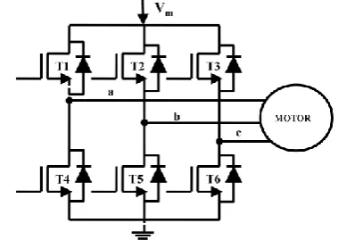
control technique will improve the efficiency of the drive. Figure.1 shows a voltage source inverter connected to a motor.
[image:2.595.331.521.267.406.2]The complete motor drive includes the controller, power converter and the motor. The power converter, referred to as inverter processes the power, is usually implemented by a Voltage Source Inverter (VSI). Controllers are used to generate gating signals for the inverter. Proper selection of inverter devices and selection of the control technique will guarantee increased efficiency of the drive. In this figure upper switches are T1, T3, T5 and lower switches are T4, T6, T2. The switching variable vectors are denoted a, b, c. These 6 switches T1 through T6 that shape the output voltage. When upper switch is turned on (i.e., a, b or, c is “1”), the corresponding lower switch is turned off (i.e., a, b or, c is “0”).But never should an upper switch and lower switch be simultaneously turned ON.
Fig 1: Three phase Voltage Source Inverter driving a motor.
1.3 Basic switching vectors and region
Fig.2.a shows the locations of the switching vectors of a 2-level inverter. The figure shows that there are eight available switching states for a 2-level inverter of which six are non-zero switching vectors and two are zero vectors. The vectors shown in Fig.2 are switched to synthesize the reference vector. The six active non-zero vectors are located at the vertices of a hexagon. The hexagon is divided into six regions marked 1 – 6. [image:2.595.344.514.639.769.2]
Table 1 shows the vectors of the 2-level inverter and the corresponding switches to be closed in order to produce the corresponding vector. It may be noted that corresponding to the 0 0 0 and 1 1 1 , either the three top switches or three bottom switches are closed resulting in no power transfer to the motor, hence are zero vectors.
Table 1: Switching vectors of a 2-level inverter and the corresponding switches closed
Switching Vectors Switches Closed
1 0 0 T1 T6 T2
1 1 0 T1 T3 T2
0 1 0 T4 T3 T2
0 1 1 T4 T3 T5
0 0 1 T4 T6 T5
1 0 1 T1 T6 T5
0 0 0 T4 T6 T2
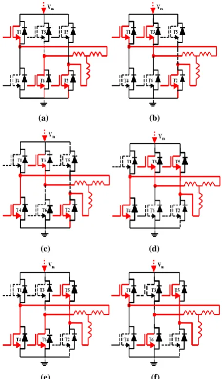
Fig.2.a Fig.2.b
Fig 2(a). Switching vectors for a 2-level inverter, Fig 2(b). Switching vectors used in proposed scheme
.
The implementation of sinusoidal commutation is complex and requires the use of high resolution encoders for accurate determination of position. Also the switching losses associated with sinusoidal commutation are also high in comparison to the trapezoidal commutation. The proposed commutation scheme implements near sinusoid commutation without use of high resolution encoders and also the number of switching is also considerably reduced, resulting in lower switching losses.
(a) (b)
(c) (d)
(e) (f)
Fig. 3: Six modes of operation in pseudo sinusoid commutation,(a)100, (b)110, (c)010, (d)011, (e)001, (f)101.
Consider the region marked II in Fig.2.b. It may be noted that the vectors located at the ends of the region are 1 0 0 and 1 1 0. A closer observation will reveal that the Phase A is clamped to 1 and Phase C is clamped to zero. The only phase which switches, is the Phase B. Fig.3 shows the different modes of operation in Pseudo Sinusoid commutation. So, from the rotor position if it is possible to identify from among the six regions of the 2-level inverter, then only one out of the three phases need to be switched. The proposed commutation scheme is pivoted on this idea of using only the non-zero vectors to synthesize the reference vector. The hall sensors mounted on the motor will provide information on the present rotor position and this can be used as information to determine the region of the 2-level inverter. Then depending on the region identified two out of the three phases need to be clamped and only one phase needs to be switched depending on the state of the PWM signal. This commutation scheme will result in number of switching to be minimum.
2.
SPEED CONTROL OF BLDC MOTOR
2.1
Modeling
The modeling of the three phase BLDC motor drive system is based on some assumptions,
All the stator phase windings have equal resistance per phase and constant self and mutual inductances.
Power semiconductor devices are ideal.
Iron losses are negligible and the motor is unsaturated.
Based on the above assumptions, the three phase input voltages [6] are expressed as follows
(2)
The electromagnetic torque can be expressed by
(3)
It can also be expressed in terms of load torque and speed by
(4)
In these equations Va , Vb , Vc indicates the stator phase
winding voltage of phase a, b, and c respectively, ea, eb, ec
indicates the back emf of each phase, ia , ib , ic be the current in
each phase, Vm be the neutral voltage, R,L and M indicates
the resistance , inductance and mutual inductance of the phase winding, Tl is the load torque, J be the moment of inertia, ω
be the angular speed, B is viscous damping coefficient
2.2 Implementation method of proposed
work
To implement the proposed novel commutation scheme with minimum switching losses and minimum harmonic contents, a new controller is developed which has fixed switching frequency as well as combined modulation and regulation. The proposed commutation scheme utilizes the six non-zero switching vectors of the 2-level inverter to synthesize the reference vector at any instant It may be noted
)
(
a a b b c ce
e
i
e
i
e
i
T
r r
l
e
B
dt
d
J
T
T
.
; )
(
; )
(
; )
(
m c c c
c
m b b b
b
m a a a
a
V e dt dI M L RI V
V e dt dI M L RI V
V e dt dI M L RI V
[image:3.595.57.276.81.203.2] [image:3.595.53.281.336.724.2]from Fig.3, that there are 6 regions. Consider the region numbered 1,the switching vectors are 101 and 100. By inspecting these voltage vectors, it is found that APH is
clamped to VDC, BPH is clamped to ground or zero voltage,
CPH will be switched depending upon PWM. For each of the
regions, similar switching strategy will be employed. For each of the regions marked 1- 6 in fig.2 the phases to be clamped and the leg to be switched are shown in Table 2
Table 2: Regions of the 2-level inverter and the corresponding phases to be clamped and the phase to be
switched .
REGION STATE OF THE PHASE
1
APH is clamped to VDC
BPH is clamped to ground
CPH will switched depends upon PWM
2
APH is clamped to VDC
BPH will switched depends upon PWM
CPH is clamped to ground
3
APH will switched depends upon PWM
BPH is clamped to VDC
CPH is clamped to ground
4
APH is clamped to ground
BPH is clamped to VDC
CPH will switched depends upon PWM
5
APH is clamped to ground
BPH will switched depends upon PWM
CPH is clamped to VDC
6
APH will switched depends upon PWM
BPH is clamped to ground
CPH is clamped to VDC
The reduction in the number of overall switching will result in lesser switching loses. Where APH represents the
phase voltage of A, BPH represents the phase voltage of B, CPH
represents the phase voltage, VDC represents the DC link bus
[image:4.595.329.531.71.209.2]voltage. The scheme of the proposed controller is shown in Fig.4. The look up table implemented accepts the hall sensor signals and the PWM signal.
Table 3: Region of a 2-level inverter as decoded form the 3 hall sensor rotor position feedback sensors
REGION HALLSENSOR
STATE
1 100
2 110
3 010
4 011
5 001
6 101
[image:4.595.337.542.539.632.2]The output of the look up table is the six gating signals to the six switches of the 2-level inverter, referred to as the 3-phase power amplifier in Figure.3. Table 3 shows the region identified according to the state of the hall sensor signals. It may be noted that the transition in the hall sensor state will occur for every electrical 60o rotation of the motor. The information received from the hall sensor signals are also used to determine the speed of the motor also. Fig 4: Controller Scheme implementing the Pseudo Sinusoid commutation.
3.
SINGLE NEURON PI CONTROLLER
In order to validate the proposed commutation scheme a novel controller is proposed. The controller is used for a PMBLDC (Permanent Magnet Brushless DC motor) based speed control system. In the closed loop speed control system the speed of the motor is compared with the reference speed and the error is fed to a PI compensator. The output of the PI compensator is used to generate the PWM signal. The proposed controller receives the PWM signal together with the signals received from the hall sensors mounted on the motor. This paper propose a new speed control by single neuron adaptive PI controller. Due to its merits such as simple structure, high efficiency, and easy implementation, the PI controller is widely use in most servo application such as actuation, robotics, machine tools and so on. However, the conventional PI controller is based on a linear model and suffer from parameter sensitivity and nonlinearity of the BLDC motor. A single neuron model is proposed based on the fact that the output of the neuron is the weight sum of all the signals coming to it. The advantage of the single neuron model is its adaptation ability acquired by adjusting the weight coefficients. Based on the adaptation ability and self study of the single neuron adaptive PI controller has the advantages of simple structure, fast response and good adaptability. The block diagram of speed control of four switch BLDC motor is shown below. Fig 5: Block diagram for entire speed control A single neuron is an information-processing unit fundamental to the operation of a neural network. A single neuron can be regarded as a nonlinear input and multi-output processing unit, which performs a transfer function f of the following type.
(5)
where y(k) is the output of the single neuron, xi(k),
ωi(k) (i = 1, 2, . , n) are the inputs and neuron connecting
weights, respectively; θ is the threshold of the neuron; f is
(
)
(
)
)
(
1
k
x
k
f
k
y
in
[image:4.595.73.265.565.663.2]called as activation function, which is usually chosen to be a nonlinear function. The single neuron PI controller is obtained based on the structure and function of a single neuron.
Fig 6: Schematic diagram of single neuron PI controller
r(k), y(k) are the desired speed and actual output speed value, respectively; e(k) is the speed error signal. The function of state transformer is to transfer the speed error e(k) to the inputs of the single neuron. The inputs of the signal neuron is set up as 2, denoted as x1(k) and x2(k) respectively; w1(k)
and w2(k) are weights of each input; K(k) is a gain coefficient;
u(k) is output of the controller.
The steps of PI controller contains the speed error, updating the weights with K is the learning rate of a neuron. The weight coefficients are tuned by the weight function, thus by tuning the PI controller the speed of the four switch BLDC motor is controlled. The regulating rule of the single neuron PI controller can be described as follows.
Step 1: Given the initial weight and learning rate of a single neuron, incremental PI controllers are used here, and the control error is
(6) y(t) be actual speed at time t, and r(t) be the reference speed at time t.
Step 2: Then the inputs of the neuron are
(7) From above equation (6) it can be seen that the two inputs
of the single neuron accord with the proportion, and integration of the feedback error e(t), respectively; and each input of the single neuron is associated with an adjustable weight which plays the same role as the parameters of a traditional PI controller, therefore, this two input single neuron based controller is called as single neuron PI controller.
Step 3: The output of single-neuron PI controller is
(8)
where ωi(t) is the corresponding weight of xi(t), and K is the learning rate of a neuron, with K >0.
Step 4: The weights of the neuron are usually trained by learning rules.
The most popular learning rules are supervisory Delta learning rule and non-supervisory Hebbian rule. To further improve the learning capability and adaptive capability of single neuron based controller for the fast and accurate real time control, an incremental type single neuron PI controller is obtained by the similar way as the incremental PI algorithm, which is described as follows.
(8) Where ηp and ηi are the learning rates of proportional and
integral controller respectively.
Comparing with the traditional PI regulator, weights ωi(k)
(i=1, 2) of the single neuron act in a similar way like the PI parameters Kp, and Ki, ω1(k)x1(k) is similar as Kp, which is
used to improve the system response speed;ω2(k) x2(k) is
similar as Ki, used to eliminate the accumulate error rapidly. Parameters of the single neuron PI controller are adjusted by training the weights of the single neuron according to the system requirement.
4.
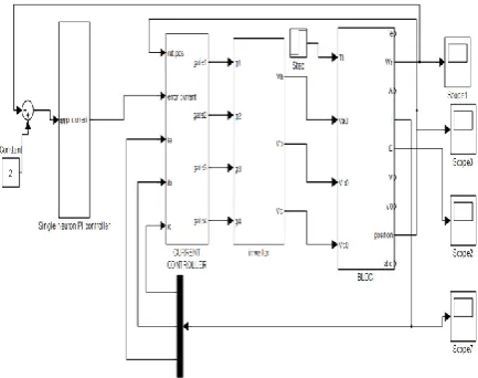
SIMULATION RESULTS
The simulation of the proposed algorithm was carried out in SIMULINK for the BLDC motor model. The parameters of the BLDC motor model used for the simulation are shown in the appendix. Fig 7. shows the entire MATLAB simulation of the proposed algorithm. Fig 8. shows that the MATLAB model of BLDC motor. It may be noted that the zero vectors of the 3 phase inverter are not used in the proposed commutation scheme. Fig.9 shows the pole voltages for the phase A of the 3 phaseBLDC motor .The leg of the inverter switches between 0 and 28V depending on the PWM. It may also be noted that at certain portion of the pole voltage the inverter leg gets clamped to VDC or 0V depending on the
rotor position sensed by the hall sensors. . For the conventional 2-level inverter, the driven motor there would be five voltage levels in the phase voltage (2VDC/3, -VDC/3, 0,
VDC/3, 2VDC/3). In Figure.5, the phase voltages have only four
levels (-2VDC/3, -VDC/3, VDC/3, -2VDC/3). This is because the
zero vectors are not used in the proposed algorithm. The absence of zero vectors in the switching vectors is not reflected in the current waveform.
Fig. 7: Simulation diagram of entire system.
)
1
(
)
(
)
(
2
t
e
t
e
t
x
)
(
)
(
)
(
t
y
t
r
t
e
)
(
)
(
1
t
e
t
x
2 1 2 1)
(
))
(
).
(
(
)
1
(
)
(
i i i it
t
t
x
K
t
u
t
u
)
(
)
(
)
(
)
1
(
)
(
1 11
t
t
ie
t
u
t
x
t
)
(
)
(
)
(
)
1
(
)
(
2 22
t
t
pe
t
u
t
x
t
[image:5.595.320.537.572.743.2]Fig 8: MATLAB model of BLDC motor
Fig 9: shows the pole voltage corresponding to phase A switching between 0-28 V.
[image:6.595.265.534.69.713.2]Fig.10: shows the steady state Back EMF in phase A
[image:6.595.330.537.76.176.2]Fig.11: shows the phase voltage corresponding to Phase A
Fig.12: shows the voltage developed across the bus voltage return and Neutral point of the motor
Fig.13: shows the phase current corresponding to each Phase
Fig.14: shows the torque characteristics
Fig.15: shows the speed characteristics.
Fig. 16 : shows the DC Bus Ripple
0 0.1 0.2 0.3 0.4 0.5 0.6 0.7 0.8 0.9 1
0 0.5 1 1.5 2 2.5 3 3.5 4 4.5 5
time(sec)
sp
e
e
d
(r
p
s)
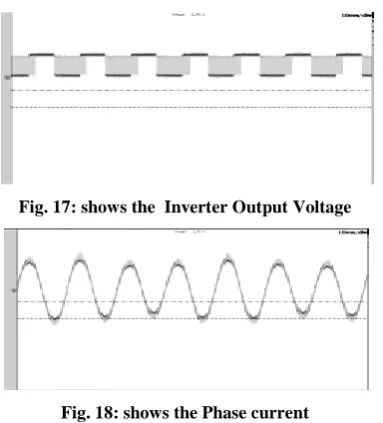
[image:6.595.56.294.101.288.2]Fig. 17: shows the Inverter Output Voltage
Fig. 18: shows the Phase current
The proposed scheme generates the three phase sinusoid at the output of the PI compensator. However according to the proposed strategy two of the phases are clamped and only one of the phases will be switched. Hence of the three sinusoids generated only one among them will be used to generate the PWM signal. The signal to be used will depend on the sector of the 2-level inverter in which the reference vector is located.
The proposed controller has been implemented as the part of a closed loop speed control system in order to validate the proposed algorithm. Fig.10 shows the Back EMF corresponding to steady state condition. Similarly, Fig.11 shows the phase voltage corresponding to the steady state. It may be noted that in comparison to the steady state voltage of a 2-level inverter, there are only 4 levels in the phase voltage in Fig.11. This is because the zero vectors are not used in the proposed algorithm. Fig.12 shows the voltage developed across the DC bus voltage return and the Neutral point of the motor. This is designated as VNO where N represents the neutral point and O represents the return line of the DC link voltage.Fig.13 shows the steady state current corresponding to the instant where the speed has been attained by the motor referred to as the steady state. Fig.15. shows the response of the closed loop speed control system implemented with the proposed controller. The speed command to the system is given as 2 rad/sec. Fig.14 shows that the torque ripple is considerably reduced in the proposed commutation scheme compared to conventional system. The reduction in torque ripple is primarily attributed to the production of sinusoidal current and Back emf by the proposed commutation scheme. Fig. 16 shows the experimental result of DC Bus ripple. Fig. 17 shows output voltage of the Voltage Source Inverter.Fig.18 shows Phase current.
5.
CONCLUSION
The proposed algorithm for implementing the speed control and Pseudo Sinusoid commutation scheme for BLDC motor has been simulated. The commutation scheme in the paper minimizes the number of switching by switching only one of the inverter leg per PWM cycle. Also the implementation of the proposed algorithm does not require complex 3 phase sinusoid generation. The rotor position feedback serves to identify the sector and hence commutation is achieved.Based on the adaptation ability and self study of the single neuron adaptive PI controller, the tuning of PI controller is possible by adjusting the weight. This tuning of PI controller leads to the speed control of BLDC motor. The algorithm can be
easily implemented and self train according to the system requirement. The simulation carried out in MATLAB/SIMULINK validates the proposed algorithm.
A
PPENDIXMOTOR PARAMETERS :
Self inductance of the winding L = 6 mH, Back EMF constant Kb = 0.6 V/rad/sec,
Torque constant Kt = 0.037N-m/A,
Motor inertia J = 0.2156,
Winding resistance/phase R = 12.5Ω,
Number of poles P = 16, Flux Density B = 0.2,
Star connected winding configuration.
6.
REFERENCE
[1] T.J.E Miller,” Brushless Permanent Magnet and
Reluctance motor drives”, oxford Science publication, UK, 1989.
[2] R. Krishnan, ”Electric motor drives modeling Analysis and control”, 2001 Prentice Hall.
[2] G. Liu and W. G. Dunford,."Comparisons of Sinusoidal Excitation and Trapezoidal Excitation of a Brushless Permanent Magnet Motor," Fourth International Conference on Power Electronics & Variable Speed Drives, ,vol.17 , pp.446-450.
[3]
F.Caricchi,F.Guilii Capponi,F.Crescimbini and L.Solero,., "Sinusoidal Brushless Drive with Low-cost Linear Hall Effect Position Sensors," in Power Electronics Specialists Conference,vol.2 , pp. 799-804, 2001. [4] C.T. Lin, C.W Hung, and C.W Liu,” position sensor lesscontrol method for four switch brushless DC motor drives”, IEEE transaction Power Electron, vol.23, no1, pp438-444, Jan.2008.
[5] Lihua Li and Keyue Smedley,., "A new analog controller for three-phase voltage generation inverters," IEEE Transactions On Industrial Electronics, Vol. 55, No.8, August 2008.
[6] C. W. Lu, “Torque controller for brushless DC motors,” IEEE Trans. Ind. Electron. vol. 46, no. 2, pp. 471–473, Apr. 1999.
[7] C.B.Jacobina, E.R.C. da Silva ,A.M.N. Lima, and R.L.A. Riberio,”Vector and Scalar control of a four switch three phase inverter,” in Proc. IEEE Ind. Conf.,1995, vol.3.pp.2422-2429.
[8]P.Pillay and R.Krishnan,”Modeling simulation and analysis of permanent-magnet motor drives . Part II :The brushless dc motor drive”. IEEE Trans.Ind.Appl.,vol.IA-25, no.2,pp.274-279,Mar./Apr.1989.
Electronics,” PROC. 27th International Conference on Microelectronics (MIEL 2010), Serbia, 16-19 May 2010. [10] Salih Baris Ozturk,William C. Alexander, Hamid A.
Toliyat, “Direct Torque Control of Four-Switch Brushless DC Motor With Non-Sinusoidal Back EMF”, IEEE Transactions on Power Electronics, vol. 25, no. 2, pp. 263- 271, Feb 2010.
[11] Farhad Aghili, “Fault-Tolerant Torque Control of BLDC Motors”. IEEE Transactions on Power Electronics, Vol.26, No-2, February 2011.
[12] Changliang Xia, Zhiqiang Li, and Tingna Shi,”A Control Strategy for Four-Switch Three-Phase Brushless DC Motor Using Single Current Sensor”, IEEE Transactions on Industrial Electronics, vol. 56, no. 6, June 2009.
[13] P.C.K.Luk and C.K Lee, ”Efficient modeling for a Brushless DC motor drive”, conf. Record of IEEE-IECON ,pp.188,1994.