Using Sticker Model to Solve the Clique Problem on
DNA-Based Computing
Sientang Tsai
*, Wei-Yeh Chen, Hui-ling Huang
Department of Information Management, Southern Taiwan University, Yuan Kung District, Tainan City , Taiwan *Corresponding Author: [email protected]
Copyright © 2014 Horizon Research Publishing All rights reserved.
Abstract
In this paper, it demonstrates how to use a sticker-based model to design a simple DNA-based algorithm for solving the clique problem. We first construct the solution space of memory complexes for the clique problem via the sticker-based model. Then, with biological operations, separate and combine, we remove those which encode illegal vertices from the solution space of memory complexes. The computation proceeds by using an inverted electronic version of gel electrophoresis to obtain a solution of the maximum clique problem.Keywords
DNA-Based Computing, NP-Complete Problems, Clique Problem1. Introduction
Feynman is the first scientist who offered the bio-molecular computation in 1961, but his idea was not implemented by experiments for a few decades [1]. Then, Adleman succeeded in solving an instance of the Hamiltonian path problem in a test tube in 1994, just by handling DNA (Deoxyribo Nucleic Acid) strands [2]. In [3], it indicated that the optimal solution of every NP-complete or NP-hard problem is determined by its characteristics. DNA-based algorithms were proposed to solve many computational problems including the satisfiability problem [4], three-vertex-coloring [5] problem, the set-splitting problem [6], maximum cut problem [7] and the binary integer programming problem [8]. One potentially significant area of application for the DNA algorithms is the breaking of encryption schemes [9]-[11]. From [12]-[14], the DNA-based arithmetic algorithms are proposed, and from [15], the DNA-based algorithms for constructing DNA databases are also offered. The major contributions of this work is to propose an easy and comprehensive method , instead of complicated data structures used in [18], to solve the clique problem.
Sticker model makes use of single-double stranded DNA molecules as physical substrates in which information is
presented. It has the following advantages that there is a random memory where no strand extension is required, computational operations use no enzymes, and its materials are at least reusable in theory. The motivation of this work is to take advantage of the experimental simplicity and feasibility, unlike the approach proposed by Adleman in [2], used in the sticker system [20]. We need only two biological operations, separate and combine, in the theoretical portion of DNA computing. Therefore our proposals are logically simplified and its feasibilities are enhanced.
The rest of the paper is organized as follows. Section 2, the sticker-based model is described in details. Sections 3, we briefly introduce the DNA operations used in the sticker-based model. Section 4 describes the algorithm for finding the clique problem to any undirected graph. Conclusions are drawn in Section 5.
2. The Sticker-Based Model
The sticker-based model employs two basic groups of single stranded DNA molecules in its representation of a bit string. Consider a memory strand, N bases in length, is subdivided into K non-overlapping regions each M bases long (thus, N = M * K). Moreover, each region is identified with exactly one bit position (or equivalently one Boolean variable) during the course of computation. Adlemam et al. [20] also designed K different sticker strands or simply stickers. Each is M bases in length, and is complementary to exactly one of the K sub-strands in the memory strands. If a sticker is annealed to its matching region on a given memory strand, then the bit corresponding to that particular region is
on for that strand. If no sticker is annealed to a region, then that region’s bit is off. Each memory strand along with its annealed stickers (if any) represents one bit string. Such partial duplexes are called memory complexes. A large set of bit string is represented by a large number of identical memory strands; each has stickers annealed only at the required bit position. Such a collection of memory complexes is called a tube.
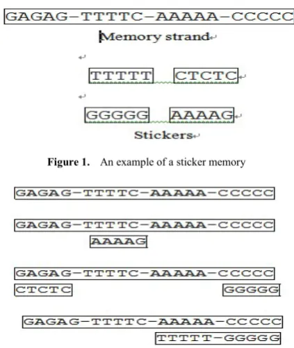
whereas each previous bit string is represented by a unique molecule. In the illustration given in Figure 1, we have a memory strand of 4 regions (K =4), each of which 5 bases in length (M =5). Thus in this case, the necessary complexes are interpreted as containing four bits of information. In particular, consider the memory complexes in Figure 2. In the first memory complex, all regions are off, whereas in the last complex the last two sub-strands are on. The binary numbers represented by these four memory complexes are 0000, 0100, 1001 and 0011, respectively.
Figure 1. An example of a sticker memory
Figure 2. Examples of memory complexes
3. Operations on the Sticker-Based
Model
DNA manipulations required for the four principal operations in the sticker-based model are combination, separation, bit setting and bit clearing [20]. We summarize these as follows:
1. Combination: This operation is to combine two test tubes into one; namely, the memory complexes from the two input tubes, with their annealed stickers undisturbed, are combined to form the multi-set union of the two inputs.
2. Separation: This operation is to separate a test tube into two new ones. One contains all original strings having a particular bit on, and the other all those with the bit off. This operation produces isolation from the test tube, exactly those complexes with a sticker annealed to the given bit’s region. Therefore, the original input tube is destroyed.
3. Bit setting: This operation is to turn on a particular bit in every string of a set, that is, an appropriate sticker is
annealed to it if that bit is off in the memory complexes, but left unchanged if that bit is already on. 4. Bit clearing: This operation is to turn off a particular bit in every string of a set, the sticker for that bit will be removed (if present) from every memory complex in the test tube.
Computations in this model consist of a sequence of operation combination, separation, bit setting and bit clearing. Additionally, inputs and outputs will be test tubes. To read the output, one memory complex must be isolated from the output test tube with its annealed stickers determined, or else it must be reported that output test tube contains no memory complexes.
The input or output test tube will be a library of memory complexes. In particular, a (k, l) library, 1 ≤ l≤k, consists of memory complexes with k sub-strands, the remaining k−l
sub-strands are off, whereas the first l sub-strands are on or off in all possible ways. Thus, the (k, l) library, viewed as a multi-set, contains 2ldifferent kinds of memory complexes.
The represented binary sequences are of the form w0k− l,
where w is an arbitrary binary sequence of length l. In the initial test tube T0, the first l sub-strands of the memory complexes represent the actual input, whereas the remaining
k−l sub-strands are used for intermediate storage and output answer. Here we need to know that all possible 2linputs are
processed in parallel.
4. Using Sticker-Based Model for
Solving the Clique Problem
4.1. Definition of the Clique Problem
Suppose that a graph G = (V, E) is an undirected graph, where V = {v1, v2, ⋅⋅⋅, vn} is the vertex set of G, and
[image:2.595.72.284.203.454.2] [image:2.595.312.549.486.700.2]E={
(
v
i,
v
j|)
v
i,
v
j∈
V
,
i
≠
j
,
(
v
i,
v
j)
denotes an edge in G}. It is obvious that |V| = n (the cardinality of a set V, denoted by |V|, represents the number of its elements), and |E| ≦n* (n −1) / 2. The complementary graph of G is the graph G = (V,E) where E= {(vi,vj |)vi,vj∈V, i≠ j, and(vi,vj)∉E}.Obviously |E| = n * (n−1) / 2 − |E|.
Figure 3. The graph of click problem
E v vi, j)∈
( . A clique of a graph G = (V, E) is a complete sub-graph of G. For example, vertices 2 and 3 in Figure 3(a) form a clique. Here we use simple notation {2, 3} instead of
) ,
(v2 v3 to represents this clique. Of course, {1, 2, 4} is also a clique of graph G in Figure 3(a). The clique problem in this work is to find the cliques of maximum cardinality [21]. For instance, the maximum clique of graph G in Figure 3(a) is {1, 2, 4}.
4.2. Using Sticker to Construct Solution Space of Memory Complex for the Clique Problem
Using the sticker-based model to construct solution space for the clique problem, we assume the given vertex set of G
is V, where V = {v1, v2, ⋅⋅⋅, vn}; the edge set of G is E, where E
= {(vi,vj)| vi,vj
∈
V, i < j}, and |E| is at most n* (n −1) / 2. Theinitial test tube T0 will be a (n, n) library of memory strands.
Here we should emphasize that any widespread applications of the sticker-based model would assume the libraries of specific sizes are readily available.
The memory complexes in the initial test tube T0 encode all possible 2n binary combinations of n vertices in G. The n
sub-strands in each memory complex can tell, by being on or off, which of the vertex v1, v2,⋅⋅⋅, vn belong to the particular
binary sequence represented by the memory complex. If the vertex vi (1≤i≤n) is on, then the corresponding ith
position of its binary sequence is 1, and this vertex vi is
considered to be possible in the clique. If the vertex vi is off,
then the corresponding ith position of its binary sequence is 0, and this vertex viis ruled out from the clique. For every edge
(vi,vj) in the complement graphG, we find its corresponding endpoints vi and vjand we can get rid of its binary sequence
whose ith and jth positions are set to 1, because they are not the possible solutions of the clique problem. Thus, for any given memory complex, we proceed as follows: looking through the n sub-strands of each memory complex, whenever we encounter two sub-strands that both are turned on (let it be the ith and jth sub-strands, the operation separate is used to differentiate between on and off), then we use the operation discard to throw away those corresponding sub-strands representing vertex vi and vj arenot the endpoints
of edge (vi, vj) in G (but they are the endpoints of edge (vi , vj)
in Gamong the n sub-strands). After having gone through all of n sub-strands of the memory complex in this way, we will find those left in the test tube T0 are the possible solutions of the clique problem. In other words, these n
sub-strands mean that those edges representing by each memory complex indeed form a clique of the graph G, except for encoding none or single vertex situations. Thus we may find a clique of maximum size among those legal solutions.
4.3. The DNA Algorithm for Solving the Clique Problem
Having remembered those binary information representations and operations used in the sticker-based
model, the following algorithm is presented to solve the clique problem. Note that the initial test tube T0 is a (n, n) library. We formalize these ideas described above as follows:
Algorithm 1:
(1) Input T0:design a memory strand K = n bit regions, then initialize a (K, n) library set in a tube called T0 with those technologies mentioned in Section 3. Thus, tube T0 encodes all possible 2n combinations of n vertices for a graph G = (V,
E), where |V| = n. Then proceed by removing those which can't be encoded or single vertex memory strands.
(2) For k =1 to |E|
Assume
e
k is an edge in G ande
k= (vi , vj),1≤ i < j ≤ n.
(2a) Separate T0 into
T
on1 andT
off1 based on bit i
(2b) Separate
T
on 1 intoT
on
2 and
T
off
2 based on bit j
(2c) Discard
T
on2
(2d) Combine
T
off1 and
T
off
2 into T0
End For
(3) Fori = 0 to n− 1
For j = idownto 0
(3a) Separate Tj into Tonj+1 and
T
j based onbit (i + 1)
(3b) Combine Tj + 1 and Tonj+1 into Tj + 1
EndFor End For
(4) For j= ndownto 1
If (detect (Tj)=="yes") then Read ( Tj) and terminate
the algorithm
End If End For
The above algorithm can be used to find the clique problem for the graph G in Figure 3(a). Here we have n = 4 vertices in Step (1) of the algorithm and construct a (4, 4) library of memory complexes in the test tube T0. For a graph with 4 vertices, each possible clique is represented by the 4 bits of the binary number b1b2b3b4 from 0000 to 1111. The ith bit set to 1 represents a vertex viin the clique, and that set to 0
represents a vertex vi out of clique. For instance, the binary
solutions. For our problem, the numbers, 1X1X and XX11, are eliminated, where X could be 0 or 1. The remainders, satisfying the definition of the clique problem, correspond to all cliques in the graph G. Their binary sequences are 0101,0110,1001,1100 and 1101.
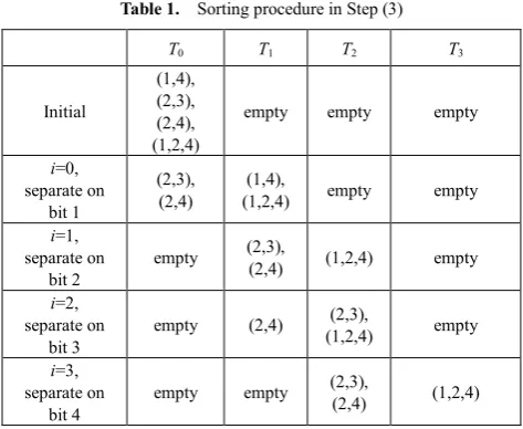
Consider the nested loop in Step (3) of the algorithm in terms of our example, we will find the initial test tube T0 includes the memory complexes representing all corresponding cliques (2, 4), (2, 3), (1, 4), (1, 2) and (1, 2, 4). After performing Step (3a) and (3b) in the nested loop, T1 and T4 are empty; T2 contains two vertices forming a clique like (2, 4), (2, 3), (1, 4) and (1, 2); T3 contains three vertices forming a clique like (1, 2, 4). This process is achieved by sorting tube T0 into a number of tubes T0, T 1, T 2, T 3, T 4, where tube Ti contains memory strands encoding i (i≥ 2)
[image:4.595.59.296.374.568.2]vertices in the clique. Table 1 describes the situation after each step in the nested loop. Following Step (4), we start with the largest indexed tube T4 and read its contents if exists. If that tube is empty, then we move on to the next highest indexed tube and so on until we find a tube that is not empty. It is obvious the clique with the largest number of vertex tells us the size of the maximum clique. Therefore, the final result of our example is T3 encoded the maximum clique (1, 2, 4) with size 3.
Table 1. Sorting procedure in Step (3)
T0 T1 T2 T3
Initial
(1,4), (2,3), (2,4), (1,2,4)
empty empty empty
i=0, separate on
bit 1
(2,3),
(2,4) (1,2,4) (1,4), empty empty
i=1, separate on
bit 2 empty
(2,3),
(2,4) (1,2,4) empty
i=2, separate on
bit 3 empty (2,4)
(2,3),
(1,2,4) empty
i=3, separate on
bit 4 empty empty
(2,3),
(2,4) (1,2,4)
Theorem 4-1: From those steps in Algorithm 1 above, the clique problem for a graph G = (V, E) can be solved, where |V| = n, and |E| = n * (n− 1) / 2.
Proof: A test tube T0 of memory complexes (DNA strands) representing all possible input bit sequences b1, b2, ⋅⋅⋅, bn− 1,
bn is yielded in Step (1). Apparently, tube T0 contains all possible solutions.
We consider the complementary graphG, Step (2) will be executed n* (n − 1) / 2 −|E| times for filtering out those memory complexes dissatisfied the condition of legal solution. The execution of Step (2a), the operation separate based on bit i produces two test tubes:
T
on1 and
T
off 1 . Thefirst tube
T
on1 includes all of the memory complexes that
have ith bit set to 1. That is to say, the ith vertex in V appears
in tube
T
on1 . The second tube
T
off1 consists of all of the
memory complexes that have ith bit set to 0, that is, the ith vertex in V does not occur in tube
T
off1 . Similarly, the
execution of Step (2b), the operation separate based on bit j
produces two test tubes:
T
on2 and
T
off
2 from
T
on
1 . The first tube
T
on2 includes all of the memory complexes that have both ith
and jth bits set to 1. That is to say, the tube
T
on2 contains
those vertices not connected in G. The second tube
T
off2
contains all of the memory complexes that have ith bit set to 1 and jth bit set to 0. That is to say, the ith vertex in V appears in tube
T
off2 , but the jth vertex in V does not occur in tube
T
off
2 .
From the definition of the clique problem in Section 4.1, tube
T
on2 includes illegal memory complexes. Hence, Step (2c)
applies the operation discard to throw away tube
T
on2 . Next,
Step (2d) uses the operation combine to pour the two tube
T
off1 and
T
off
2 into
T
0. This is to say, T0 currently contains legalsolutions. After the remaining steps are performed, tube T0 consists of those memory complexes representing all legal cliques.
Whenever the outer loop in Step (3) is executed, the inner loop is performed (i+1) times. On the first execution of the outer loop, the inner loop is only performed one time. Therefore, Step (3a) and (3b) are both done once. Step (3a) uses the operation separate based on bit 1 to produce two test tubes:
T
on1 and
T
0 . The first tubeT
on1 contains all
memory complexes that have the first bit set to 1. The second tube T0 consists of all of the memory complexes that have the first bit set to 0. That is to say, the first tube
T
on1 encodes
every clique with the first vertex in G, and the second tube T0 represents every clique without the first vertex in G. Then, Step (3b) applies the operation combine to pour
T
on1 and an
empty tube T1 into T1. It produces n new tubes after performing Step (3a) and (3b) n*(n+1)/2 times. The tube Tk
(1 ≤k≤n) encodes those memory complexes that contain k
vertices.
Because the clique problem is to find the maximum-size clique, tube Tn is first detected by the operation read. If the
answer is yes, then the tube Tn at least contains a
maximum-size clique and terminates the algorithm. Otherwise, we continue to read the next tube Tn-1 until a maximum-size clique is found in some tube detected.
4.4. The Complexity of Algorithm 1
Theorem 4-2: Suppose that a graph G = (V, E), where |V| = n, and |E| = n * (n− 1) / 2. The clique problem for G can be solved with O (n2) biological operations in the sticker-based model.
Proof: Algorithm 1, applied for solving the clique problem, consists of three main steps. Step (2) is used to remove illegal memory complexes from all of the 2n possible
heavier strands are dragged further to the right than lighter strands. It is mainly used to figure out the number of vertices in every legal clique in the tube. It is indicated from
Algorithm 1 that Step (3a) or Step (3b) individually takes n
* (n + 1) / 2 separate and combine operations. Step (4) is employed to search a clique with maximum size from legal solutions. It is shown that Step (4) at most takes n read operations. From the operation counts mentioned above, we find the time complexity of the worst case for this algorithm is O (n2) operations in the sticker-based model.
5. Conclusions
The sticker model uses DNA strands as a computational substrate to store information. It uses bonded and non-bonded state to encode those data. Each DNA strand is broken up into bits which are a unique subsequence. A sticker represents one bit segment and can only be attached to some proper positions. The bit is on if the sticker is attached, and it is off otherwise. This model makes use of separation by hybridization as a main operation. It requires neither strand extensions nor enzymes. Furthermore, its materials are reusable. It demonstrates that the formation and breaking of covalent bonds in the sticker model are not intrinsic. This means costly and short-lived materials such as enzymes are not necessary in the sticker model, nor are energetic and costly processes such as PCR. It is shown that in the sticker model a single essential biotechnical sequence-specific separation suffices for constructing a general-purpose molecular computer. Separation errors in the sticker model can be theoretically reduced to a tolerable level by invoking a trade-off between time, space and error rates when the algorithm is designed [20].
Although the sticker-based model is a biological computation theory, its potential for physical realization is expectable. We have many evidences showing the ability of DNA computing in solving NP-complete search problems. In future studies, authors hope that the comparisons of time complexity and experimental feasibility of the proposed algorithms between different models of DNA computation will be done, especially for solving typical NP-complete problems.
Acknowledgements
I am very grateful to Dr. W. L. Chang for his constructive suggestions to improve this research.
REFERENCES
[1] R. P. Feynman. In miniaturization, D.H. Gilbert, Ed., Reinhold Publishing Corporation, New York, pp. 282-296,1961.
[2] L. Adleman. Molecular computation of solutions to combinatorial problems, Science, 266, pp. 1021-1024,1994. [3] M. Guo, W. L. Chang, M. Ho, J. Lu and J. Cao. Is optimal
solution of every NP-complete or NP-hard problem determined from its characteristic for DNA-based computing. Biosystems, Vol. 80, No. 1, pp. 71-82, 2005.
[4] R. J. Lipton. DNA solution of hard computational problems, Science, 268, pp. 542:545, 1995.
[5] M. Amos. DNA Computation, Ph.D. Thesis, of computer science, the University of Warwick, 1997.
[6] W. L. Chang, M. Guo and M. Ho. Towards solution of the set-splitting problem on gel-based DNA computing, Future Generation Computer Systems, Vol. 20, Issue: 5, pp. 875-885, 2004.
[7] D. Xiao, W. Li, Z. Zhang and L. He. Solving the maximum cut problems in the Adleman–Lipton model. BioSystems, Vol. 82, pp 203-207, 2005.
[8] C. W. Yeh, C. P. Chu and K. R. Wu. Molecular solutions to the binary integer programming problem based on DNA computation. Biosystems, Vol. 83, Issue: 1, pp. 56-66, 2006. [9] D. Boneh, C. Dunworth and R. J. Lipton. Breaking DES using
a molecular computer. In Proceedings of the 1st DIMACS Workshop on DNA Based Computers, 1995,American Mathematical Society. In DIMACS Series in Discrete Mathematics and Theoretical Computer Science, Vol. 27, pp. 37-66, 1996.
[10] L. Adleman, P. W. K. Rothemund, S. Roweis and E. Winfree. On applying molecular computation to the Data Encryption Standard. The 2nd annual workshop on DNA Computing, Princeton University, DIMACS: series in Discrete Mathematics and Theoretical Computer Science,American Mathematical Society, pp. 31-44, 1999.
[11] W. L. Chang, M. Ho and M. Guo. Fast parallel molecular algorithms for DNA-based computation: factoring integers, IEEE Transactions on nanobioscience, No. 2, pp. 149-163, 2005.
[12] F. Guarnieri, M. Fliss and C. Bancroft. Making DNA add, Science, Vol. 273, pp. 220–223, 1996.
[13] M. Ho. “Fast parallel molecular solutions for DNA-based supercomputing: the subset-product problem. BioSystems, Vol. 80, pp. 233–250, 2005.
[14] H. Ahrabian and A. Nowzari-Dalini. DNA simulation of nand Boolean circuits. Advanced Modeling and Optimization, Vol. 6, No. 2, pp. 33-41, 2004.
[15] Alfons Schuster. DNA databases. BioSystems, Vol. 81, pp. 234–246, 2005.
[16] Q. Ouyang, Kaplan, D. Peter, S. Liu and A. Libchaber. DNA solution of the maximal clique problem, Science, Vol. 278,pp 446-449, 1997.
[17] R. R. Sinden. DNA Structure and Function. Academic Press, 1994.
[18] G. Paun, G. Rozenberg and A. Salomaa. DNA Computing: New Computing Paradigms.Springer-Verlag, New York, 1998.
Computational Power of DNA. Discrete Applied Mathematics, Special Issue on Computational Molecular Biology, Vol. 71, pp. 79-94, 1996.
[20] S. Roweis, E. Winfree, R. Burgoyne, N. V. Chelyapov, M. F. Goodman, Paul W.K. Rothemund and L. M. Adleman, A sticker based model for DNA computation, 2nd annual
workshop on DNA Computing, Princeton University. Eds. L. Landweber and E. Baum, DIMACS: series in Discrete Mathematics and Theoretical Computer Science, American Mathematical Society, pp. 1-29, 1999.