An Overview of Malaysia Green Technology Corporation Office
Building: A Showcase Energy-Efficient Building Project in Malaysia
Ng Ban Huat & Zainal Abidin bin Akasah
Department of Construction and Building Engineering, Universiti Tun Hussein Onn Malaysia 86400 Parit Raja, Batu Pahat, Johor, Malaysia
Tel: 60-16-604-8535 E-mail: ngbanhuat@hotmail.com Tel: 60-7-453-7314 E-mail: zainal59@uthm.edu.my
Received: July 28, 2011 Accepted: August 21, 2011 doi:10.5539/jsd.v4n5p212
Abstract
Malaysia Green Technology Corporation office building is designed based on Zero Energy Building (ZEB) concept; however its Building Energy Index (BEI) has yet to achieve zero. This research focuses on the application of energy-efficient design of the office building; identify the problems causing BEI of the studied office building which did not achieve zero BEI; and to propose approaches that can improve energy efficiency for the office building. Interviews session with the office building management team, architect and energy consultant have been carried out. The outcome of the research shows that energy-efficient design and renewable-energy technology applied in the office building are passive design, active systems, and building integrated photovoltaic systems (BIPV). The inefficiency in the cool part of the cooling system, air movement, and chillers are the problems that have been identified. It is recommended that, continuous research is needed to ensure ZEB concept applied effectively in each type of buildings.
Keywords: Energy-efficient design, Renewable-energy technology, Zero energy building, Malaysia green technology corporation office building
1. Introduction
In the current situation, the depletion of natural resources such as fossil energy has given pressure to every nation in the world in fulfilling the ever increasing demand of fossil energy. According to Boyle (2004) the world’s fossil energy consumption rate has reached 82 percent. The over use of fossil energy is the main contributor towards global climate change (United States Environmental Protection Agency [USEPA], 2010), whereas the excessive consumption of fossil energy will wind up in releasing a large amount of greenhouse gasses. Hence, the approaches such as improvement of energy efficiency, increasing the use of renewable-energy; the preservation of a healthy building indoor environment; and increasing the sustainability of natural resources are among the approaches catching the world’s attention (National Science and Technology Council [NSTC], 2008). Energy-efficient building is the building fulfills the needs stated above and capable of reducing the dependence of fossil energy use. With regards to energy efficiency and the use of sustainable energy in buildings, the Malaysian government has launched a few projects to act as a demonstration, educational and enhance public awareness programs (Ahmed, 2008). Malaysia Green Technology Corporation office building is one of the showcase projects that have high performance in its energy efficiency.
Malaysia Green Technology Corporation office building or formerly known as Malaysia Energy Center (PTM) is a demonstration project for commercially viable examples of sustainable initiatives for modern buildings in Malaysia and the region (Saravanan, 2008). The building is designed based on Zero Energy Building (ZEB) concept; the aim of the project is to demonstrate self-sufficient energy by using current technology.
2. Problem Statement
In order to reduce the building’s energy consumption, Malaysia has launched the development project of Malaysia Green Technology Corporation’s new office building, which is situated in Bandar Baru Bangi. The design of the building is fully based on ZEB concept. The project was completed in the year 2007; however the office building is still unable to fulfill its energy needs after three years operation. The Building Energy Index (BEI) of the building yet to achieve zero. Up until now, researches are still being carried out with the aim to increase the energy efficiency of the building (Choong, 2009).
3. Research Objectives
The research objectives of this study are:
i) To identify the application of energy-efficient components in the office building.
ii) To identify the problems causing the Building Energy Index (BEI) of the office building yet to achieve zero.
iii) To propose the approaches capable to increase the energy efficiency of the building. 4. Research Methodology
The methodology for this research is divided into 3 phases. The first phase is to identify the problems and the formulation of research objectives. The research objectives are formulated based on the identified problems. Research scopes are determined through data collection during the literature review of energy-efficient building. The second phase is to conduct a visit and interview in the selected building. Photos were taken in order to identify the energy-efficient design of the building. The interview session was carried out with the key peoples of the building for example architects, consultants, and building management team with the aim to identify the problems causing the BEI of the building yet to achieve zero; and to propose the approaches capable to increase the energy efficiency of the building. The collected data is analyzed in order to achieve the research objectives. In the third phase, the research finding is concluded and future study recommendations are provided.
5. Literature Review
According to Torcellini, et al. (2006) ZEB is a residential or commercial building with greatly reduced energy needs through efficiency gains such that the balance of energy needs can be supplied with renewable technologies. ZEB concept was existence since the early 20th century ago; the construction of solar house is one of the mankind’s efforts towards zero fossil energy goals (Butti & Perlin, 1980). In the year 1995, the use of solar technology for air ventilation purposes had been applied in Bliss House which is situated in Melbourne, Florida, United States (Bliss, 1955). In the following development, Professor Korsgaard from the Danish Technical University and his colleagues had successfully realized the concept of ZEB by constructing a Zero Energy House (ZEH) at the Thermal Insulation Laboratory in 1975 (Gram-Hanssen & Jensen, 2005).
5.1 Factors Affecting the Building’s Energy Consumption
According to Chan (2004), factors affecting the building’s energy consumption can be divided into two categories, they are, non design factors and passive design factors.
5.1.1 Non Design Factors
Non design factors are the factors affected by occupancy and management; environmental standards; and climate.
i) Occupancy and management
People or occupants play an important rule of a building’s energy consumption. Occupants use cooling or heating system to achieve comfort. There are four broad aspects to consider, they are intensity of building occupancy; type of activity; user attitude and behavior; lastly, management and organization. According to a study by Kofoworola & Gheewala (2009), the energy consumption rates are higher during the operation hour compared to the non operational hour. The result shows that the occupant behavior is determined the building’s energy consumption.
ii) Environmental standards
iii) Climate
Climate affects the energy consumption in a building primarily by influencing the space cooling and heating requirements. In order to reduce the effects of climate, building requires the installation of technical systems such as cooling, heating, ventilation systems, thus more energy is required to operate the system (Willkomn, 2001).
5.1.2 Passive Design Factors
Passive design factors that affect the building’s energy consumption rate are size and shape; orientation; planning and layout; thermo physical properties; window systems and construction detailing.
i) Size and Shape
The research done by Wilkinson & Reed (2006) shows that small office building has a low energy consumption rate compared to large office buildings, this is because a large building requires more energy compared to smaller building for its cooling or heating purposes. A higher energy consumption rate is caused by the larger space needed to be cooled or heated.
ii) Orientation
Generally building’s orientation affecting cooling and heating system of a building. Apart from that, the orientation also affects the natural ventilation of a building. According to Chia et al. (2007), the building wall facing perpendicular to the north-south axis has a higher indoor temperature compared to the building wall facing perpendicular to east-west axis which is due to the thermal effect in the building.
iii) Planning and Layout
According to Aziz & Adnan (2008), planning and layout of a building are an important factor in reducing the building energy consumptions. This is because a large space requires more energy for its cooling or heating proposes, the heights of a ceiling and space volume are among the factors affecting the energy consumption. iv) Thermo physical properties – thermal resistance & thermal capacity
The properties of materials which affect are another factor affecting the rate of heat transfer in and out of a building. A research done by Zhang et al. (2006) shows that the room built with high thermal resistance walls consumes lower energy compared to low thermal resistance wall. This is because; lessen heat transfer from outside of the building built from the high thermal resistance wall.
v) Window systems
The size, location, shape and orientation of glazed areas in a building will have a critical effect on both the heat gains and solar gains of a building because glazed areas have the highest heat gain per unit area. According to Stein (1977) the school with the highest energy use per square foot in New York City was a completely sealed building with windowless classroom.
vi) Construction detailing
The research done by Okba (2005) explains the importance of construction detailing in controlling or reduce the thermal transition to building. The infiltration of cold air losses at the junctions of different materials especially between roof joists and exterior walls is similar to the effect of leaving the door open in an air conditioned room. 6. Scope of research
i) This research was carried out in Malaysia Green Technology Corporation’s office building, Bandar Baru Bangi;
ii) This research is focused on the ZEB components applied in the office building. The information is retrieved through the interview with the building management team and the architect involved during the design process;
iii) This research is focus on the problems causing the office building’s BEI did not achieve zero. The term energy used in this research is referring to the energy used during the operation of the building. The data were retrieved through interviews with the building management team, and;
iv) To acquire views from the office building’s management team, architect, and energy consultants involved during the design process.
7. Analysis and Findings
objectives; they are interviews and observation/field of study. Interview sessions with the office building management team, architect and energy consultant have been carried out. A visit to Malaysia Green Technology Corporation office building has been done. The outcomes from the interview and field of study are discussed as the following subtopics.
7.1 First Objective: Energy-efficient Components in the Office Building
Energy-efficient design and renewable-energy technology applied in the office building are passive design, active systems, and building integrated photovoltaic systems (BIPV).
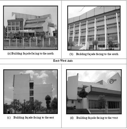
7.1.1 Passive Design a) Building Orientation
The orientation of the office building is north-south axis orientation, where, the building walls that have large surface area are being designed to locate perpendicular to the north-south axis, while the building walls that have small surface area are being designed to locate parallel to the east-west axis as shown in Figure 7.1. The goal of this approach is to maximize the daylighting of the building and reduce the thermal impact. (Figure 7.1: North-South axis and East-West axis orientation)
b) Insulation System i) Internal Wall
The internal walls are installed with a layer of rock wool insulation as shown in Figure 7.2, in order to reduce thermal effects in the office building. (Figure 7.2: Internal wall installed with a rock wool insulation layer) ii) External Wall
The external walls are installed with two layers of rock wool insulation as shown in Figure 7.3, because it receives greater thermal effects compared to internal walls. (Figure 7.3: External wall installed with a rock wool insulation layer)
c) Roof
The roof section of the building is installed with Styrofoam with the aim to reduce the heat transfer through the roof and enter the building. Below are the explanations of roof design of the building.
i) Flat roof
The flat roofs of the office building are installed with 150mm thick Styrofoam as shown in Figure 7.4. (Figure 7.4: 150mm thick Styrofoam)
ii) Slanting roof
Mineral wool is installed on the slanting roof as shown in Figure 7.5. (Figure 7.5: Mineral wool) iii) Uppermost floor
The polystyrene layer is installed on the uppermost floor of the office building as shown in Figure 7.6, wherein the roof of the area housed the building integrated photovoltaic systems (BIPV). (Figure 7.6: Polystyrene layer is installed on the uppermost floor)
d) Daylighting
i) Daylight source from the top of the building
The daylight source from the top of the building is the source of light from the roof and the atrium with BIPV panel functioned as a roof.
Skylight
Direct sunlight is blocked by skylights, and only the diffuse light is permitted to admit through the skylight by passing through spectral selective glazing/double glazing window and then the diffuse light is reflected into the building as shown in Figure 7.7. (Figure 7.7: Schematic diagram of the light admitted through the skylight)
Daylight source from atrium roof
Light source from PV panels acts as atrium roof allowing daylight enters the building through PV panel as shown in Figure 7.8. (Figure 7.8: Light source enters the building through BIPV panel)
Daylight sources from the side of the building
to enter the building. Diffuse light is then reflected by mirror light shelf, and afterward, it is reflected to the part of a ceiling that has high reflective characteristics. Suspended ceiling are not installed because the suspended ceiling will obstruct the diffuse light from reflecting into the building. (Figure 7.9: Schematic diagram of the diffuse lights admit into the building)
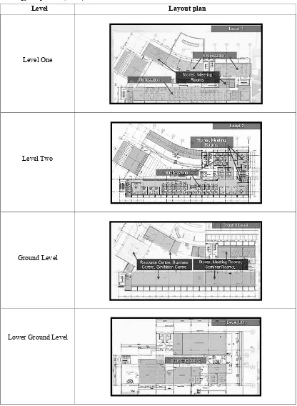
Internal layout
The workplace is placed near to the window area so that daylights are permitted to enter the workplace area thoroughly, while the storage room is placed in the area which has fewer window features as shown in Table 7.1. (Table 7.1: Office building’s internal layout)
Glass window
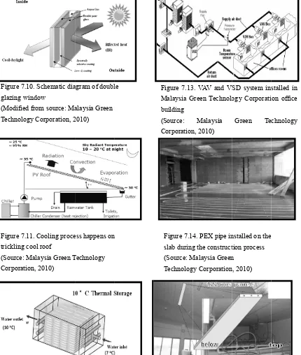
Type of glass window installed in the building is the double glazing window as shown in Figure 7.10. Double glazing window is capable of reflecting heat from the building by only allowing diffuse light enters the building. (Figure 7.10: Double glazing window)
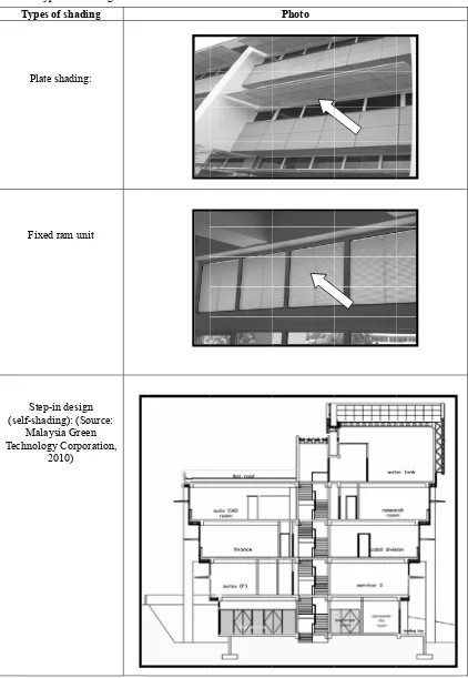
Shading
Shading plate, fixed ram unit, and step-in design are the types of shading applied in the office building as shown in Table 7.2. (Table 7.2: Types of shading applied in the office building)
Reduced internal load
Reducing the plug load is the approach taken by the Malaysia Green Technology Corporation in order to reduce the internal load. PC with CRT monitor is replaced by laptop or PC with LCD monitor.
7.1.1 Active System a) Cooling System
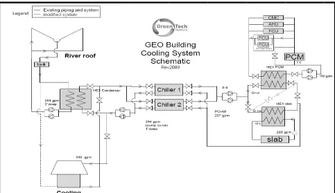
The cooling system of the building encompasses rainwater collection, trickling cool roof, cooling tower, chiller, Air Handling Unit (AHU), Phase Change Material (PCM), and radiant cooling system.
i) Trickling Cool Roof
The trickling roof is an alternative approach to replace the cooling tower. At the night time or during the low operation period, the temperature of the water of the rainwater collection tank is reduced by draining through the trickling cool roof; the process is assisted by radiation, convection, evaporation, and also the low temperature from the surroundings which is 10 degree Celsius to 20 degree Celsius. Next, the chilled water is drained to the chiller condenser; the chiller condenser is functioned as the heat eliminator. The chilled water is stored in the chiller and will be used for the next day. The process happens on the trickling cool roof is shown in Figure 7.11. (Figure 7.11: Cooling process happens on the trickling cool roof)
ii) Cooling Tower
Cooling tower in the Malaysia Green Technology Corporation office building has high energy-efficient characteristics. The usage of the cooling tower is complementing to the trickling cool roof. Cooling tower will function when the trickling cool roof is not functioning.
iii) Rainwater collection
The filtered rainwater will be used for cooling purposes, and also for the irrigation system of the building. The rainwater collection tank has a normal capacity which is 5280 gallons of water and its efficient capacity is 3700 gallons of water.
iv) Phase Change Material (PCM)
Phase Change Material (PCM) function in storage and release of thermal energy. PCM tank used in the building has dimension 3m x 3m x 2.5m as shown in Figure 7.12. (Figure 7.12: Phase Change Material (PCM))
v) Air Handling Unit (AHU)
Air Handling Unit (AHU) has high energy-efficient characteristics, which is its energy consumption are low compared to conventional AHU.
vi) Variable Air Volume (VAV), and Variable Speed Drive (VSD)
vii) Radiant Cooling System
Chilled slab
The chilled slab is the slab installed with the PEX pipe, which is functioned to drain the coolant under the floor so that the temperature in the room can be reduced through reduction of floor temperature. Figure 7.14 shows PEX pipe installed in the slab during the construction. (Figure 7.14: Chilled slab with PEX pipe)
Chilled Metal Ceiling (CMC)
Chilled metal ceiling (CMC) has 18 degrees Celsius of its temperature; it is capable of reducing the room temperature from top to bottom. The installed panel has the cooling capacity of 93 watts/m2 as shown in Figure
7.15. (Figure 7.15: Chilled Metal Ceiling (CMC)) b) Energy-Efficient Lighting System
i) Energy-Efficient Electrical Lighting System
Energy-efficient light, for example, T5 and CFL are installed with a proper circuit system. The goal is to reduce energy consumption. The LED task light used in the building has 6.2 watt energy consumption rates. The energy-efficient lights of the building have 300-400 Lux. as shown in Figure 7.16. (Figure 7.16: Energy-efficient light)
ii) Control and Sensors
Control and sensor system used in Malaysia Green Technology Corporation office building are daylight sensor and present sensor as shown in Figure 7.17 and Figure 7.18. (Figure 7.17 and Figure 7.18: Control and sensor system)
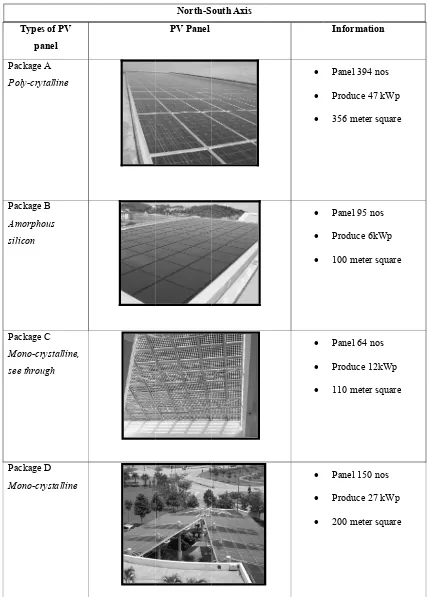
c) Renewable-Energy Technology
Building integrated photovoltaic system (BIPV) is the renewable-energy technology applied in the office building. The BIPV system is the PV panel built on the building structure; usually BIPV is installed on the roof. Types of the photovoltaic (PV) panel used in the office building are shown in Table 7.3. (Table 7.3: Types of photovoltaic panel)
7.2 Second Objective: The Problems Causing Building Energy Index (BEI) of the Office Building Did Not Achieve Zero
The problems causing Building Energy Index (BEI) did not achieve zero is attributed to the cooling system design of the building.
a) Cold Side of Cooling System
The problem is due to the cold side of the cooling system where the Phase Change Material (PCM) or ice storage did not turn into ice during the operation. This is due to supply water of the chiller did not reach 7 degrees Celsius continuously for at least 8 hours when it reached the Phase Change Material (PCM) tank. Currently, the temperature of the supply water reached 11 degrees Celsius and above. Due to that reason chiller has to operate in a longer hour during the day in order to compensate the lack of cooling source from the ice storage system. b) The Problem of Air Movement
The size of the Fan Coil Units (FCU) as shown in Figure 7.19 of the building is too small and cooled air could not be distributed evenly into the room. Hence chiller has to use more energy to reduce the room temperature. (Figure 7.19: Fan Coil Unit)
c) The Oversized Chiller
The size of the current chiller is 85 rth, it is too big and tends to consume more energy during its operation.
7.3 Third Objective: The Approaches That Can Improve Energy Efficiency of the Office Building
7.3.1 Distribution of Energy Consumption for Malaysia Green Technology Corporation Office Building
Based on Figure 7.20, the highest energy consumption rate is cooling system, 72 percent, followed by other equipment, 21 percent, and lastly lighting system, 7 percent. Hence the reduction of energy consumption should be focused on the cooling system, followed by others equipments and lighting system. This is because the cooling system consumed most of the energy compared to others. (Figure 7.20: Distribution of energy consumption for Malaysia Green Technology Corporation Office Building)
7.3.2 The Proposed Approaches That Can Improve Energy Efficiency of the Office Building a) Increase the Air Flow in the Building
b) Increase the Efficiency of the Cold Side of Cooling System
To ensure the lowest temperature in the PCM tank, modification to the cold side of the cooling system, by changing the system from parallel, to become serial as shown in Figure 7.22; meaning the chilled water from the chiller (which is 5.5 degree Celsius) will be passed straight to the PCM tank initially, and then it will go to the floor slab cooling system. (Figure 7.22: Schematic diagram of the cooling system)
c) Reduce the Chiller Size
The current chiller size has to be reduced to 45 rth. A smaller chiller will consume less energy compared to large chiller.
d) Increase the Temperature of the Slab Radiant Cooling System
The original temperature of the slab radiant cooling system is 16 degree Celsius. The operation of the chiller can be reduced by increasing the temperature to 18 degree Celsius. This is because; the less operation of the chiller can contribute to increase the efficiency of the chiller and heat pump. Hence, the energy consumption rate can be reduced. The low temperature of the slab radiant cooling system not only increases the operation of chiller but can also cause the floor to become slippery due to the condensation process. The suitable temperature is around 16 degree Celsius to 21 degree Celsius.
e) Reduce the Electricity Base Load
Electricity base load for Malaysia Green Technology Corporation office building is 6kw to 10kw. The electricity base load still can be reduced. Where, use a laptop instead of a personal computer with LCD monitor. In addition, use fiber-optic light, because fiber-optic light only uses sunlight as its light source.
f) Solar Cooling System
Solar thermal cooling is one of the types of solar cooling system. Solar thermal cooling uses solar thermal collector to ignite the absorption type of cooling system. The absorption cooling system can function well by only using thermal energy; hence, energy consumption can be reduced.
g) Use Desiccant of Solar Cooling System
Desiccant like silica gel has the ability to eliminate air moisture and their functions are important to make sure the cooling system can operate effectively. The desiccant can be regenerated by using solar thermal energy and not electricity.
8. Conclusion and Recommendations
The energy-efficient components applied in the office building are passive design, active system, and renewable-energy technologies. These systems have features that complement each other to ensure the office building can achieve energy efficiency. The problems causing Building Energy Index (BEI) of the Malaysia Green Technology Corporation did not achieve zero are due to the ill performance from cooling systems, air movement problem and oversized chiller. Increase the efficiency of the cold side of the cooling system; increase the air flow in the building, reduce the chiller size, increase the temperature of slab radiant cooling system, reduce the electricity base load, using the solar cooling system, and use desiccant in a solar cooling system is the approaches had been identified able to increase the office building’s energy efficiency.
Overall, after the interview with the key peoples from the building management team and the building designers, the author has successfully identified the cause of the low performance of the office building is due to the building’s air conditioning system. The recommended measures should be taken in order to increase the building performance. However, the recommended measures could not assure the consistency of the building performance. Hence, a continuous study is needed in order to improve the energy efficiency of the building. The future research could be focused on the occupants’ perspective towards building’s energy-efficient design. Since the occupants are the end user of the building, by taking account of the occupant perception could further improve the building performance from time to time. The country like Malaysia should fully occupy the advantages of using solar energy in terms of its climate. Technologies such as PV panels need to be commercialized so the cost of these materials could be further reduced. Thus, the involvement and cooperation of various parties are essential in realizing a sustainable environment.
References
Ahmed, A. Z. (2008). Integrating sustainable energy in buildings: a case study in Malaysia. In Proceedings from the FAU conference, Copenhagen, Denmark.
Aziz, A. A. & Adnan, Y. M. (2008). Incorporation of innovative passive architectural features in office building design towards achieving operational cost saving – the move to enhance sustainable development. In
Proceedings from the Pacific Rim Real Estate Society (PRRES) Conference. Kuala Lumpur, Malaysia.
Bliss, R. W. (1955). Design and performance of the nation’s only fully solar-heated house. Air conditioning, Heating, and Ventilating, 52(92).
Press, (Chapter 1).
Butti, K. & Perlin, J. (1980). A Golden Thread, 2500 Years of Solar Architecture and Technology. Van Nostrand Reinhold Company.
Chan, S. A. (2004). Energy Efficiency: Designing Low Energy Buildings Using Energy 10. Retrieved January 15, 2010, from http://pam.org.my/Library/cpd_notes/Energy-Efficiency.pdf
Chia, S. L., Ahmad, M. H. & Ossen, D. R. (2007). The effect of geometric shape and building orientation on minimizing solar insulation on high-rise buildings in hot humid climate [Electronic version]. Journal of Construction in Developing Countries, 12(1), 27-38, Retrieved September 4, 2010, from http://web.usm.my/jcdc/hbp.htm.
Choong, M. Y. (2009, December 15). Major breakthrough. The Star. Retrieved March 31, 2010, from http://thestar.com.my/lifestyle/story.asp?file=/2009/12/15/lifefocus/5274286&sec=lifefocus
Gram-Hansen, K. & Jensen, J. O. (2005). Green building in Denmark from radical ecology to consumer-oriented market approaches. In S. Guy & S. A. Moore (Eds.) (2005). Sustainable architectures cultures and natures in Europe and the North America. New York: Spoon Press.
Kofoworola, O. F. & Gheewala, S. H. (2009). Life cycle energy assessment of a typical office building in Thailand [Electronic version]. Energy and Buildings, 41(10), 1076-1083. Retrieved April 2, 2010, from http://dx.doi.org/10.1016/j.enbuild.2009.06.002
Kok, C. (2009, October 31). Malaysia’s green energy gap. The Star. Retrieved March 31, 2010, from http://biz.thestar.com.my/news/story.asp?file=/2009/10/31/business/5011674&sec=business
Malaysia Green Technology Corporation (2010) (n.d.). [handout]. Malaysia Green Technology Corporation. National Science and Technology Council. (2008). Federal research and development agenda for net-zero energy, high-performance green buildings. Retrieved March 17, 2010, from http://www.bfrl.nist.gov/buildingtechnology/documents/FederalRDAgendaforNetZeroEnergyHighPerformanceG reenBuildings.pdf
Okba, E. M. (2005). Building envelope design as a passive cooling technique. In Proceedings from the International Conference “Passive and Low Energy Cooling for the Built Environment. Santorini, Greece. Raman, M. (2009, July 7). Mitigating climate change: what America’s building industry must do. Design Intelligence. Retrieved March 31, 2010, from http://www.di.net/articles/archive/3097/
Saravanan (Ed.). (2008, February). Malaysia - PTM ZEO Building. Roof and Façade Asia, 5,46.
Stein, R. G. (1977). Architecture and energy. Conserving energy through rational design. Garden City, New York: Anchor Press / Doubleday.
Torcellini, P., Pless, S., Deru, M. & Crawley. D. (2006). Zero energy buildings: a critical look at the definition.
Proceeding of 2006 ACEEE Summer Study on Energy Efficiency in Buildings, 3-286. Retrieved January 15, 2010, from http://mini2.borgco.se/conference_proceedings/ACEEE_buildings/2006/Panel_3/p3_24/paper
United States Environmental Protection Agency. (2010). Climate change: greenhouse gas emissions. Retrieved October 14, 2010, from http://www.epa.gov/climatechange/emissions/index.html#ggo
Wilkinson, S. J. & Reed, R. G. (2006). Office building characteristics and the links with carbon emissions [Electronic version]. Structural Survey, 24(3), 240-251. Retrieved April 2, 2010, from http://dx.doi.org/10.1108/02630800610678887
Willkomn, W. (2001). Appropriate technology for a climatically responsive low energy architectures. In A. Krishnan, S. Yannas, N. Baker & S. V. Szokolay (Eds.) (2001). Climate responsive architecture a design handbook for energy efficient buildings (pp. 165-175). New Delhi: Tata McGraw-hill Publishing Company Limited.
Zhang, Y., Lin, K., Zhang, Q. & Di, H. (2006). Ideal thermophysical properties for free-cooling (or heating) buildings with constant thermal physical property material [Electronic version]. Energy and Buildings, 38(10), 1164-1170. Retrieved September 4, 2010, from http://dx.doi.org/10.1016/j.enbuild.2006.01.008
Notes
Table 7.1 Malaysia Green Technology Coproration office building’s internal layout (Source: Malaysia Green Technology Corporation, 2010)
Level Layout plan
Level One
Level Two
Ground Level
Table 7 T
(sel
Tech
7.2 Types of sh Types of shad
Plate shading
Fixed ram un
Step-in desig lf-shading): (S
Malaysia Gre hnology Corpo
2010) hading
ing
g:
nit
gn ource: en oration,
Table 7.3 Type Types pa Package Poly-cry Package Amorpho silicon Package Mono-cry see throu Package Mono-cry
es of PV panel
s of PV anel A talline B ous C rystalline, ugh D rystalline l PV Panel
North-SSouth Axis
Informatio
Panel 394 n
Produce 47
356 meter s
Panel 95 no
Produce 6kW
100 meter s
Panel 64 no
Produce 12k
110 meter s
Panel 150 n
Produce 27
Figure 7.1 Malaysia Green Technology Corporation office building’s orientation (a) Building façade facing to the north (b) Building façade facing to the south
East-West Axis
Figure 7.2 (a) Office building internal wall
(b) & (c) Internal wall installed with insulation system during construction of the building
(Source: Malaysia Green Technology Corporation, 2010)
Figure 7.3 (a) Office building external wall
(b) & (c) External wall installed with insulation system during construction of the building
[image:13.595.60.279.74.277.2](Source: Malaysia Green Technology Corporation, 2010)
Figure 7.5. Mineral wool layer is installed on the slanting roof
[image:13.595.302.479.76.184.2](Source: Malaysia Green Technology Corporation, 2010) Figure 7.4. The photo showed the installation of Styrofoam during the construction of the roof
(Source: Malaysia Green Technology Corporation, 2010)
b c
Cement mortar Rock wool insulation
Wire mesh
a
b c
Rock wool insulation
[image:13.595.301.485.242.368.2]Cement mortar Wire mesh
Figure 7.6. Polystyrene layer is installed on the uppermost floor of the office building (Source: Malaysia Green
[image:13.595.60.284.350.569.2] [image:13.595.302.489.421.527.2]Figurre 7.7. (a) Diffu (Modifi (b) Spec (c) Dayl
use daylight ad ed from sourc ctrally selectiv light source fro
Figu (source
(c)
dmitted throug e: Malaysia Gr ve glazing.
om sky light
ure 7.9. (a) Diff e: Malaysia Gr (b) ) High reflectiv
gh sky light. reen Technolo
ffuse daylight e reen Technolo ) Mirror light s ve surface on t Fi bu
gy Corporatio
entered into bu gy Corporation shelf
the ceiling sur igure 7.8. Ligh uilding through
n, 2010)
uilding n, 2010)
face
ht source enter h BIPV panel
Figure 7.10. glazing wind (Modified fro Technology C Figure 7.11. trickling coo (Source: Mal Corporation,
Figure 7.12. P (Source: Mala Corporation, 2
Schematic dia dow
om source: Ma Corporation, 2
Cooling proce ol roof
laysia Green T 2010)
Phase Change M aysia Green Te 2010)
agram of doubl
alaysia Green 2010)
ess happens on
[image:15.595.57.255.73.204.2] [image:15.595.61.491.78.586.2]Technology Material (PCM echnology le n M) Figure 7.13 Malaysia G building (Source: Corporation Figure 7.1 slab during (Source: M Technolog Figure 7.15. (Source: Ma Technology
3. VAV and V Green Technolo
Malaysia n, 2010)
4. PEX pipe in g the construct Malaysia Green gy Corporation
Chilled metal alaysia Green
Corporation, 2
SD system in ogy Corporati
Green Te
nstalled on the tion process n
n, 2010)
l ceiling (CMC
2010)
stalled in ion office
chnology
Figur
Figur
Figure
re 7.16. (a) Com (b) Fluo (c) LED
e 7.17. Daylig
7.18. Present mpact Fluoresc orescent Light D Light ght sensor sensor
cent Light (CF t
F
Figur for M office (Mod Techn Figu FL) Coolin system 72% Ligh syst 7
Figure 7.19. Cu
re 7.20. Distrib Malaysia Gree e building dified from
nology Corpor
ure 7.21. Sugge ng
m,
hting
tem,
7%
urrent Fan Coi
bution of energ en Technolog
source: Ma ration, 2010).
ested Fan Coil
il Unit (FCU)
gy consumptio gy Corporatio alaysia Gree Unit (FCU) Othe equip nt, 2
Figure 7.22: (Malaysia
Schematic dia a Green Techno
agram of the c ology Corpora