DEVELOPMENT OF SELF BALANCING PLATFORM ON
MOBILE ROBOT USING PID CONTROLLER
MAZITA BINTI MAT ALI
A project report submitted in partial fulfillment of the requirement for the award of the
Degree of Master of Electrical Engineering
Faculty of Electrical and Electronic Engineering Universiti Tun Hussein Onn Malaysia
vii
ABSTRACT
ABSTRAK
ix
TABLE OF CONTENT
THESIS STATUS CONFIRMATION i
SUPERVISOR’S CONFIRMATION ii
DEDICATION iii
ACKNOWLEDGMENT iv
ABSTRACT vii
ABSTRAK viii
TABLE OF CONTENTS ix
LIST OF TABLES xiv
LIST OF FIGURES xv
LIST OF SYMBOLS xvii
LIST OF ABBREVIATIONS xviii
I INTRODUCTION
1.1 Project Background 1
1.2 Problem Statement 2
1.3 Problem Objectives 3
1.4 Project Scopes 3
1.5 Organization of Report 4
II LITERATURE REVIEW
2.1 Previous Case Study 5
2.2 PID Controller 7
2.3 IMU Implementation 7
2.3.1 Gyroscope 7
2.3.2 Accelerometer 7
2.4 Mathematical Modelling 8
2.5 The Controlled platform 8
xi
III RESEARCH METHODOLOGY
3.1 Project Methodology 11
3.2 Project Activities 12
3.3 The Hardware 13
3.3.1 Sensor IMU Board 15
3.3.2 Mobile Robot 19
3.3.3 Board Arduino Uno 20
3.3.4 DC Servo Motor 22
3.3.5 DC Motor and its Driver 25
3.4 PID Controller Design 26
3.4.1 Characteristic Of The PID Controller 28 3.4.2 Implementation of a PID controller 28 3.4.3 Tuning the PID controller 29
3.5 Model of a R/C servo Motor 30
3.6 Complementary Filter 31
3.7 Conclusion 33
IV RESULT AND ANALYSIS
4.1 Robot Design 34
4.2 Microcontroller Programming 39
4.3 Sensors Integration 42
4.3.1 Gyrometer 42
4.3.2 Accelerometer 43
4.4 Filter Design 47
4.4.1 Integration 47
4.4.2 Low-Pass Filter 47
4.5 Simulation Result 48
4.5.1 Continuous to Discrete Conversion 49
4.5.2 Pitch Axis Control 51
4.5.2.1 PID control in Pitch Axis 51 4.5.2.2 Tuning the gains in Pitch Axis 54 4.5.3 Roll Axis Control 55 4.5.3.1 PID control in Roll Axis 57 4.5.3.2 Tuning the gains in Roll Axis 58
4.6 PID Control Analysis 60
xiii
V DISCUSSION AND CONCLUSION
5.1 Discussion 64
5.2 Conclusion 65
REFERENCES 67
APPENDIX A 70
APPENDIX B 72
LIST OF TABLES
2.1 List of Platform Projects 10
3.1 Characteristic of PID Controller 28
4.1 Measurement Result For RC Servo 38
4.2 Angle Estimate by Experiment 48
4.3 Analysis of PID controller result for Roll and
xv
LIST OF FIGURES
3.1 Flow Chart of process Methodology PS1 11
3.2 Flow Chart of process Methodology PS2 12
3.3 Platform Schematic 13
3.4 External installation Components 14
3.5 IMU sensor 6 DOF 15
3.6 Gyro Axes (θ ) Relative to PCB Axes ( θ) 17 with Orientation Errors (θ and Φ)
3.7 Orientation of Axes of Sensitivity and Polarity 17 of Rotation +Z +X +Y
3.8 The Chassis of mobile robot 19
3.9 Differentially steered 3 wheeled Mobile Robot 20
3.10 Arduino Development board 21
3.11 Atmel Atmega 328 microcontroller 21
3.12 The graphical user interface (GUI) of Arduino Compiler 22 3.13 Servomotor circuit diagram 22
3.14 Servo Arrangement 23
3.15 Servo Body Brackets 24
3.16 Servo "C" Brackets 24
3.17 An Image of the DC motor driver. 25
3.18 Block diagram of PID closed loop 26
3.21 Block diagram of an RC Servo motor 30 3.22 Electro-Mechanical scheme of a DC motor 30 3.23 Complementary Filter in block diagram form. 32 4.1 Mobile robot with a platform is in a stationary 34 4.2 Mobile robot with a platform on upward ramp. 34 4.3 Mobile robot with a platform on downward ramp 36 4.4 Design Of Self Balancing Platform On Mobile Robot 37
4.5 Degree of servo Vs Time 39
4.6 Voltage Vs Time 39
4.7 Sketch Flow Chart 41
4.8 Accelerometer Gravity Measurement 45
4.9 Stairstep open loop response 49
4.10 Stairstep close loop response 50
4.11 Output Response of step Input Kp=5 51
4.12 Output Response for Kp=5 with 5% step disturbance 52 4.13 Output Response of step input Kp=5 Ki=0.01 53 4.14 Output Response for Kp=5 Ki=0.01 with 5% step disturbance 53 4.15 Output Response of step input Kp=5 Ki=0.01 Kd=0.01 54 4.16 Output Response for Kp=5 Ki=0.01 Kd=0.01
with 5% step disturbance 55
4.17 Output Response of step Input Kp=2 56
4.18 Output Response for Kp=2 with 5% step disturbance 56 4.19 Output Response of step Input for Kp=2 Ki=0.1 57 4.20 Output Response for Kp=2 Ki=0.1 with 5% step disturbance 58 4.21 Output Response of step input Kp=2 Ki=0.1 Kd=0.01 59 4.22 Output Response for Kp=2 Ki=0.1 Kd=0.01
with 5% step disturbance 59
4.23 Closed loop for pitch (axes-Y) 61
xvii
LIST OF SYMBOL
G - Gravity θ - Angle t - Time
J - Moment of Inertia
e(t) - Back Electromotive Force τ - Torque
I - Current
R - Electric Resistance
L - Electric inductance
Ke - Back electromotive Force Co-efficient B - Damping Ratio Of The Mechanical System
V - Voltage
LIST OF ABBREVIATIONS
xix
LIST OF APPENDICES
APPENDIX TITLE
A Gantt chart for PSM 1 and PSM 2 69
B Project Coding Matlab 71
CHAPTER 1
INTRODUCTION
1.1 Project Background
Designing a mobile robot with special capabilities has become a trend these days for a variety of universal human consumption. It also fits well with the needs and nature of the human lifestyle. Different forms and uses, mobile robots have been designed and are now in the market worldwide.
A mobile robot comprises of three main parts including sensors, logical processing unit and actuator. In this project, a robot that can maintain an upright and balanced position on a platform is designed and developed. The robot consists of Inertial Measurement Units (IMU) sensors, microprocessor and motors. The design is designed with Matlab and the resulting parameters are used and burned into Arduino UNO controller. The main purpose of the controller is to fuse the wheel encoder, gyroscope and accelerometer sensors to estimate the attitude of the platform and then to use this information to drive there action wheel in the direction to maintain an upright and balanced position platform.
2
In this project, the PID will be used because it is relatively easy to implement yet practical. Besides that, PID controller has only three adjustable parameters that can be determined from several techniques. Previous research has shown that PID controller has shown good results in terms of response time and accuracy when the parameters i.e, Kp , Ki and Kd, are properly tuned.
1.2 Problem Statements
Control systems are often designed to improve stability, speed of response, steady-state error, or prevent oscillations. Many researchers wants to produce a mathematical equation that is able to determine the position of a very accurate motor position, thus the steady state error should be zero. DC motor systems have played an important role in the improvement and development of the industrial revolution. Therefore, the development of a more efficient control strategy that can be used for the control of a DC servomotor system and a well defined mathematical model that can be used for off line simulation are essential for this type of systems. Servomotor systems are known to have nonlinear parameters and dynamic factors, so to make the systems easy to control, conventional control methods such as PID controllers are very convenient. Also, the dynamics of the servomotor and outside factors add more complexity to the analysis of the system, for example when the load attached to the control system changes.
Due to these parameters and factors, this study will apply the PID controller to make the steady-state error, due to continuous disturbance, to be zero. Accordingly this project will review the principles of PID that is used to control the servo movement that depends on the angle captured by the IMU. This project uses the PID to compensate the robot body inclination to stabilize the platform. Among other performance requirements are to reach the final position of the motor position very quickly without excessive overshoot. In this case, focusing on systems that have a finish time of 10 ms and the overshoot is smaller than 25%.
1.3 Project Objectives
The aim of this project is to implement PID controller to a mobile robot to maintain its flatness on a moving platform. The objectives of this project are as follows:
a) To design and develop a mobile robot and a flat platform. b) To design a PID controller to maintain the robot flatness
c) To simulate the controller using Matlab and analyse its performance. d) To integrate the controller into the mobile robot.
1.4 Project Scopes
The scopes of study are as follows:
a) Using mobile platform kits available in the market. b) Using sensor fusion to measure the tilts in the X-axis and Y-axis.
c) Using PID as the flatness controller.
d) Using arduino Uno as the mainboard of the mobile robot.
1.5 Organization of Report
As an overview, the structure of this report is organized as follows :
Chapter 1 describes a general introduction of the project, problem statement project aims and project scope.
4
Chapter 3 discusses the methodology of the project which provides a detailed description of the design to develop a mobile robot using PID controller to maintain the platform flatness. It also discusses about the hardware which has been used in the project.
Chapter 4 discusses about the result and analysis. It also includes the design of a mobile robot with a flat platform.
CHAPTER 2
LITERATURE REVIEW
2.1 Previous Case Study
Conducting initial review research is very critical in understanding self balancing platform control techniques. The review of research about related literature conducted in this project summarizes some of topics related to the techniques used for the balancing of platform based on Dc motor position. Comparisons between the present project and the related topics of existing information will also be discussed. The methodologies and the techniques used by other researchers around the globe on the balancing platform topic will also be reviewed.
Meena et al. (2011) proposed a design for a servo motor controller in discrete-time system to obtain the transfer function of the PID controller design. MATLAB / Simulink has been used to confirm the effectiveness of this new design method, which provides a simple and powerful way to design a speed controller for servo motor.
It also extracted a DC servo motor mathematical model and equations and there were three different motion controllers that were designed and simulated to control the velocity of the motor.
6
Masakazu et al. (2005) proposed a tuning method for PID controller that considers changes in system characteristics. It is about the concept of using the optimization of PID controller tuning, depending on the obstacles on the control input derivatives and considering model uncertainties caused by changes in the system dynamics. Partial model matching method was used to evaluate performance and control while the reference referred to interference and repression compared to the tracking properties.
Arpit et al. (2012) proposed a performance comparison of PID and Fuzzy logic controller using different defuzzification techniques for positioning control of dc motors. The result of the fine-tuned PID controller gives relatively less overshoot and settling time with no steady state error. The fuzzy logic controller with different defuzzification techniques gives zero % overshoot and lesser settling time.
In a paper titled ‘Attitude Estimation Using Low Cost Accelerometer and Gyroscope’ written by Young Soo Suh (2003), it shows two different sensors which are the accelerometer and gyroscope that exhibit poor results when used separately to determine the attitude which is referred as the pitch angle or roll angle. However, the gyroscope can combine with accelerometer to determine the pitch or roll angle with much better result with the use of Kalman filter.
Tomislav et al (2012) proposed self-balancing mobile robot tilter. It provides a summary of work done in the field of electronic, mechanical design, software design, system characterization and control theory. Robotic system model and simulation results of various control methods required for the stabilization of the system were studied. Dynamic effects become increasingly important in assessing performance limits in robotic. The processes where the project was carried out including design and production of certain parts of the integration section, electronic, mechanical and software.
The use of plant transfer function had several performances, such as using a step response and unit impulse function, the parameters change, how to control the torque and speed using the input voltage and current.
2.2 PID Controller
This project concerns the development of a mobile robot with a platform, which can be levelled using PID controller. The main objective is to control the flatness of the platform efficiently with a low cost hardware without limiting the strength and performance of the whole system. There are various stages that have been used to stabilize the platform such as modelling the system, obtaining the data from sensors and determining how the control algorithms will be implemented. V.J. Van Doren (2009) suggested a two wheeled robot to perform the balancing and control of mobile robots. In this project the Proportional, Integral, Derivative (PID) has been implemented to control the flatness of a mobile robot platform. PID has proven to be popular among the control engineering community.
As stated by the author of article Vance J. VanDoren (2009), “For more than 60 years after the introduction of Proportional-Integral-Derivative controllers, remain the workhorse of industrial process control”.
PID controller will be extensively discussed in Chapter 3.
2.3 IMU Implementation
2.3.1 Gyroscope
8
proportional to the angular displacement of the sensor Braun,T.,Sutherland ,and Alistair (2002). More about gyroscope can be found in Chapter 3.
2.3.2 Accelerometer
As stated by A. Warnasch, and A. Killen (2002), the tool that measures the inertial force in the opposite direction of free fall acceleration vector in terms of g-force is acceleration. So, gravity acceleration shows 0g power during free fall down constantly at 1g. It will be supported by the ground with a force equivalent of 1g, when the accelerometer is at rest on the surface of the earth. Because of that, it will show a constant downward force perpendicular to the ground 1g rest. To obtain the tilt angle using the Pythagorean Theorem can also use these features. Readers are referred to Chapter 3 for more on accelerometer.
2.4 Mathematical Modelling
Modelling is the process of identifying the principal physical dynamic effects to be considered in analysing a system, writing the differential and algebraic equations from the conservation laws and property laws of the relevant discipline, and reducing the equations to a convenient differential equation model (Robert, 1999). In order to develop the control system, mathematical model is established to predict the behaviour before applied into real system. Actually, the dynamics refer to a situation which is varying with time (Ernest, 1972). The dynamic performance of a balancing robot depends on the efficiency of the control algorithms and the dynamic model of the system. Mathematical modelling of DC motor will be discussed in Chapter 3.
2.5 The Controlled platform.
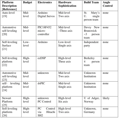
“self-leveling platform” yields a number of different platform concepts of varying complexity and sophistication. Table 1 below lists the qualities of each design and the differences between them and the concept proposed by this paper. The author selected eight completed designs for comparison. These designs were selected using their similarity in form and function to the proposed platform as the main criteria.
[image:23.595.119.521.328.723.2]Note that some of the platforms do not have a complete design description or parts list. Those will be compared using the pictorial or video evidence available via the references.
Table 2.1 - List of Platform Projects
Platform Description [Reference]
Budget Electronics Hardware Sophistication
Build Team Angle Control Auto-level [19] Mid-level Arduino Digital Servos Mid-level Two axis
St. Mary’s U. single person team none Automotive self-leveling [20] Mid-level PIC18F452 micro-controller Mid-level ~Three axis
Devry New Brunswick ~3 person team none Self-leveling Surface [21] Low-level
Arduino Low-level Single axis Independent party none Self-leveling platform [22] High-level
ezDSP High-level Three axis
Berkeley 4 person team none Automotive self-leveling [23] Mid-level
unknown Mid-level Two axis
Unknown Institution
none
self- leveling platform [24]
Mid-level
dsPIC Mid-level Single axis Unknown Institution none Stewart Platform [25] High-level unknown PC Control High-level Six axis
U of Adger, Norway likely Self-leveling platform [26] High-level
10
2.6 Conclusion
CHAPTER 3
RESEARCH METHODOLOGY
3.1 Project Methodology
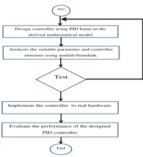
This project is done in three phases. The first phase is to understand and design the mobile robot as well as to implement the theories in the real hardware. The second phase is to understand the PID controller and its characteristic and to design and implement the controller into the robot. The last phase is to analyse the controller performance using M-file in Matlab and compare it with the response of the real hardware.
Figure 3.1 shows a general procedure of the project implementation during PS1 while Figure 3.2 illustrates the procedure during PS2.
Research topic selection
Decide the project’s tittle , objective and scope
Literature review and methodology
Design a mobile robot with a flat platform.
PS2
Start PS1
[image:25.595.165.366.505.739.2]12
PS2
Design controller using PID hand on the
derived mathematical model
Analysis the suitable parameter and controller
structure using matlab/Simulink.
Implement the controller to real hardware.
Evaluate the performance of the designed PID controller
End Test
3.2 Project Activities
[image:26.595.172.460.97.413.2]The process of executing this project is quite challenging because it involves several phases which include understanding the underlying theories, designing the robot as well as the PID controller. To make the process systematic, a Gantt Chart has been formulated. Gantt Chart is very important in order to complete this project on time. It starts with discussing with supervisors on the topic for the project, objectives, scopes and related things. Study on the literature is also planned in the Gantt Chart. Before proceed the to the PID controller design phase, it is very important to learn how to use the Simulink Matlab, which is also stated in the chart. Implementation and works of the project are summarized into the Gantt chart, as shown in appendix A.
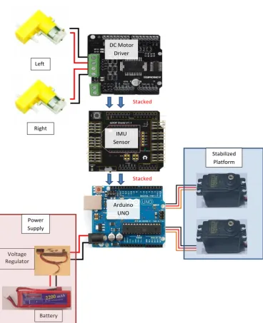
3.3 The Hardware
[image:27.595.212.406.242.385.2]The self-correcting platform consists of two platforms (Figure ), the “top” platform (smaller wood piece), which is autonomously controlled, based on initial user input, which is where the IMU sensor is installed and the angle of tilt is measured.
Figure 3.3 : Platform Schematic
An Arduino Uno board, ADXL325 accelerometer, ITG 3205 Gyrometer , two MMG 995 servos, and a Li Po battery control the upper platform tilt angle. The following sections describe the mechanics, electronics, and programming aspects of the platform. The Arduino board connections to the IMU sensor and servos are illustrated in
14
Stacked
Stacked
Left ire
Right
DC Motor Driver
IMU Sensor
Arduino UNO
Stabilized Platform
Voltage Regulator
[image:28.595.131.500.119.573.2]Battery Power Supply
Figure 3.4 : External installation Components
However, the servos used for this board require more power than the Arduino board can supply from the 5V power pin. Because of this, the servos are powered using an external power source, a 9V battery.
The servomotor used to manually control the platform are supplied with 5V from the Arduino board. It is the reduction in voltage supply to the analog pins which signals the board to send an angle signal to the servos. The accelerometer is powered by the Arduino board’s on-board 3.3V power. The ADXL325 accelerometer will send different signals through the analog pins depending on the supply voltage.
3.3.1 Sensor IMU Board
[image:29.595.150.476.410.616.2]To address the issue of measurement noises and the limitations of measurements by either the accelerometer or gyroscope alone, we will need to combine the readings from both the accelerometer and the gyroscope in a meaningful way so that we could use the strengths from both sensors to obtain a more accurate result than either measurement alone could provide.
Figure 3.5 : IMU sensor 6 DOF
16
One of the disadvantages of using accelerometer individually is that the device is sensitive to vibration since vibration contains lot of acceleration components. One solution that Young suggested is that a low pass filter is required to limit the high frequency.
a) Sensor Gyroscope
Gyroscope can measure the rate at which the rotation is taking place and the rotation angle for a given time interval is governed by:
(t)= t1t2G(t)dt (3.1)
where G(t) is the gyroscope reading with respect to the rotation direction. When the time interval is small, the gyroscope reading can be treated as a constant and can be approximated as a above equation:
(t) (t1)+G(t)(t2−t1)= (t1)+G(t) t... (3.2)
Gyroscope measurement is largely immune to none angular movement and thus far less susceptible to vibrations and lateral accelerations mentioned previously. Drifting effect will happen if the angular measurement is cumulative, any minute error in measurements will manifest over time. Thus gyroscope alone cannot be used to reliably measure the inclination angle either.
Figure 3.6 : Gyro Axes (θ ) Relative to PCB Axes ( θ) with Orientation Errors (θ and Φ)
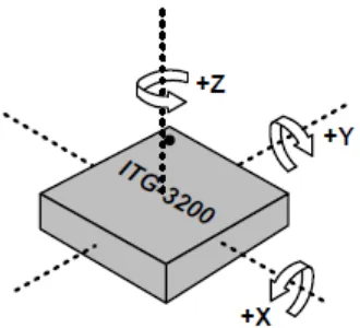
Orientation
Figure 3.7 shows the orientation of the axes of sensitivity and the polarity of rotation.
Figure 3.7 : Orientation of Axes of Sensitivity and Polarity of Rotation +Z +X +Y
b) Sensor accelerometer
[image:31.595.231.396.439.589.2]18
accelerometer metric because it defines the baseline for measuring acceleration. Additional stresses can be applied during assembly of a system containing an accelerometer. These stresses can come from, but are not limited to, component soldering, board stress during mounting, and application of any compounds on or over the component. If calibration is deemed necessary, it is recommended that calibration be performed after system assembly to compensate for these effects.
For the need to get a good measurement of the current inclination angle in order to control the platform’s movements. Inclination Angle Calculation can can be calculate as:
=tan−1AyAx=sin−1Ax A2x+A2y=sin−1gAx (3.3) In the equations above, Ax is the accelerometer reading along its x axis and Ay is the accelerometer reading on its y axis. When the robot is stationary, g is the gravitational constant (which translates into the accelerometer reading on the y axis when the accelerometer is lying flat). In this studies, are interested in getting a calculation in which the tilt angle is small because our goal is to ensure that the deviation from equilibrium (usually equilibrium is reached when the inclination angle close to 0 depending on the weight distribution of the robot) is as small as possible. So that can further simply the above equation for small inclination angles:
The values measured for X0g and Y0g correspond to the x- and y-axis offset, and compensation is done by subtracting those values from the output of the accelerometer to obtain the actual acceleration:
XACTUAL = XMEAS − X0g
YACTUAL = YMEAS − Y0g
The ADXL345 can automatically compensate the output for offset by using the offset registers (Register 0x1E, Register 0x1F, and Register 0x20). These registers contain an 8-bit, twos complement value that is automatically added to all measured acceleration values, and the result is then placed into the DATA registers.
Because the value placed in an offset register is additive, a negative value is placed into the register to eliminate a positive offset and vice versa for a negative offset. The register has a scale factor of 15.6 mg/LSB and is independent of the selected g-range.
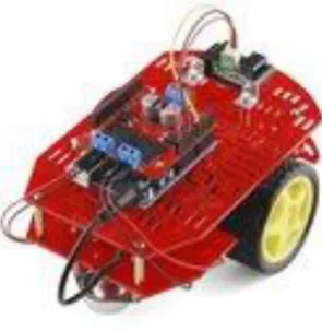
3.3.2 Mobile Robot
[image:33.595.238.386.592.744.2]Mobile robots that are used in this project is ready made. It features two gear motors with 65mm wheels and a rear caster. The chassis plates are cut from acrylic with a wide variety of mounting holes for sensors, controllers, power, etc. Simply bolt the two pre-cut platforms together, attach the motors and caster and robotics controller. It includes all of the parts needed to assemble the chassis as well as a 4xAA battery holder with barrel jack termination.
20
a) 3 Wheels Mobile Robots
The 3-wheel mobile robot has two rear wheels and an independently rotating front wheel. The robot can change direction by varying the relative rate of rotation of two separately driven rear wheels. If both wheels are driven in the same direction and speed, the robot will go straight.
[image:34.595.208.419.326.481.2]The rotation center can fall anywhere in the line joining two wheels. The center of gravity in this type of robot has been put in the triangle formed by the wheel. If too heavy mass attached to the free side of the spinning wheel, the robot will tip over.
Figure 3.9 : Differentially steered 3 wheeled Mobile Robot Source [28]
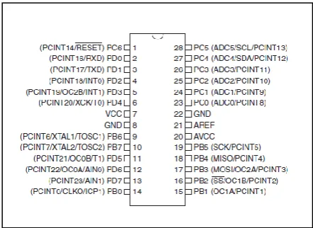
3.3.3 Board Arduino Uno
The device operates between 1.8-5.5 volts. The overview of the device as shown in figure 3.9 and figure 3.10. (Arduino.cc, 2012).
Figure 3.10: Arduino Development board
Figure 3.11: Atmel Atmega 328 microcontroller
Arduino is an open-source electronics prototyping platform based on flexible, easy-to-use hardware and software. It's intended for artists, designers, hobbyists, and anyone interested in creating interactive objects or environments.
[image:35.595.215.436.327.488.2]22
Figure 3.12: The graphical user interface (GUI) of Arduino Compiler
3.3.4 DC ServoMotor
DC servomotors are one of the main components of automatic systems; any automatic system should have an actuator module that makes the system to actually perform its function. The most common actuator used to perform this task is the R/C servomotor. A servomotor system consists of different mechanical and electrical components, the different components are integrated together to perform the function of the servomotor. Figure 3.13 above shows a typical model of a servomotor system (Nise, 2008).
[image:36.595.198.425.542.691.2]The servos supporting and controlling the top platform are arranged in order to control the pitch and roll. Note that pitch and roll are only subjective directions and are used to describe the motion. Since the platform has no “front” or “back” the terms pitch and roll are meaningless descriptions of the rotations about the X and Y axis. A close up view of the servo arrangement and axis’ is illustrated in Figure 3.14.
Figure 3.14 : Servo Arrangement
This servo arrangement is a more efficient use of space and limits the amount of slop compared to linkages and hinges as seen in other designs. The Y axis servo is controlled by the Y axis data stream from the accelerometer and vice versa for the X axis. Note that the X axis servo motion is in-plane with the photo while the Y axis would rotate out of plane.
The servos are installed into aluminum brackets illustrated in
Figure 3.15. These brackets allow the servo to be installed onto the bottom and top platforms. The servo “C” brackets (
Figure 3.16) are then used to attach the servo bodies, via the body brackets, to themselves and the platforms. The “C” brackets attach to the body and to the rotating servo horn.
24
Figure 3.15 : Servo Body Brackets [19]
Figure 3.16 : Servo "C" Brackets [19]
[image:38.595.206.417.375.533.2]REFERENCES
[1] R.S.Meena,Vikas Kumawat(2011) .Controller Design For Servo Motor
Using MATLAB .In Proceeding of National Conferences on Advances &
Research in Electrical System Technology ( AREST 2011).
[2] Popescu, Cristina; Paraschiv, Nicolae; Cangea, Otilia.(2011) Comparison Between Pid And Fuzzy Controllers Used In Mobile Robot Control
annals of daaam & proceedings;jan2011, p223
[3] Kotaki, Masakazu; Yamakawa, Yuji; Yamazaki, Takanori; Kamimura, A Tuning Method for PID Controller That Considers Changes in System
Characteristics. ASHRAE Transactions. 2005, Vol. 111 Issue 2, p13-22. 10p.
[4] Arpit Goel., et al. (2012) Performance Comparison Of PID And Fuzzy Logic Controller Using Different Defuzzification Techniques For Positioning
Control Of DC Motors. Journal of Information Systems and Communication
ISSN: 0976-8742 & E-ISSN: 0976-8750, Volume 3, Issue 1, pp.-235-238.
[5] Young Soo Suh.(2003) .Attitude Estimation Using Low Cost Accelerometer
And Gyroscope.Proceedings KORUS 2003. The 7th Korea-Russia
International Symposium on Volume: 2 Page(s): 423 - 427 vol.2
[6] Andrea Demetlika, Tomislav Tomašić, Mladen Crneković (2012)
Selfbalancing Mobile Robot Tilter.FAMENA issue 3, volume 36, Zagreb [7] Hany Ferdinando, Heri Saptono Warpindyasmoro, Stanley Kardinal Jusuf. (2001) Developing Mathematical Model of DC Servo Motor Using Bond
Graph 1st Kentingan Physics Forum ,Surakata
[8] V.J. VanDoren, “PID: Still The One,” Control Engineering, October 2003. Retrieved
[9] D. Simon, Kalman Filtering With State Constraints: A Survey Of Linear And
Nonlinear Algorithms, IET Proceediings in Control Theory & Applications,
vol. 4, no. 8, pp. 1303-1318, 2010.
68
[11] A. Warnasch, and A. Killen, Low cost, high G, micro electro-mechanical
systems (MEMS), inertial measurements unit (IMU) program, IEEE
Position Location and Navigation Symposium, 2002, pp. 299-305.
[12] Robert L.Woods(1999).Modeling And Simulation Of Dynamic Systems.New Jersey: Prentice Hall.
[13] Ernest O. Doebelin.(1972).System Dynamics.Modeling And
Response.USA:Charles E. Merril Publishing Company.
[14] Makableh, Y. (2011). Efficient Control Of DC Servomotor Systems Using Backpropagation Neural Networks.
[15] Nise, Norman S.. Control Systems Engineering. Fifth edition 2008.
[16] MATLAB/Simulink User’s Guide, 1998, The Math Works Inc, Natick, MA,
[17] Retrieved on Jan 15 ,2013 ,from
http://www.princeton.edu/~mae412/TEXT/NTRAK2002/292-302.pdf
[18] Arduino.cc. (2012), Arduino Uno Rev 3. Retrieved on Jan 15, 2013, http://arduino.cc/en/Main/ArduinoBoardUno
[19] Auto-Leveling Platform – St. Mary’s University http://engineering.stmarytx.edu/~nechon/
[20] Devry New Brunswick
http://www.youtube.com/watch?v=f9ALAvE3gBQ
[21] Self -leveling surface with arduino
http://www.youtube.com/watch?v=cTUBDagKdbA&feature=related
[22] Self-Leveling Platform
http://www.me.berkeley.edu/ME102/Past_Proj/f08/group_09/ intro_objective.html
[23] Self-leveling platform
http://www.youtube.com/watch?v=TiTRUwU7kRs
[24] ECE572SelfLevelingPlatform
http://www.youtube.com/watch?v=CuN_ZkLK0gM&NR=1
[25] Stewart Platform University of Adger, Norway
http://www.youtube.com/watch?v=WmKnnp1xTPg&NR=1
[27] Proposed self-leveling controlled platform
http://www.youtube.com/watch?v=vmf1ThwrNM0
[28] Retrieved on Apr 15 ,2013 ,from
http://en.wikibooks.org/wiki/Robotics/Types_of_Robots/Wheeled
[29] Retrieved on Apr 15 ,2013 ,from


![Figure 3.9 : Differentially steered 3 wheeled Mobile Robot Source [28]](https://thumb-us.123doks.com/thumbv2/123dok_us/8773701.900225/34.595.208.419.326.481/figure-differentially-steered-wheeled-mobile-robot-source.webp)