1410 DATA PROCESSING SYSTEM BULLETIN
AUTOCODER: PRELIMINARY SPECIFICATIONS
This bulletin is a minor revision of the previous edition, Form J24-1433-1. It incorporates the amendments published in Technical Newsletters Nos. N28-0015 and N28-0017. No other changes have been made.
Autocoder is an advanced symbolic programming sys-tem for the IBM 1410 Data Processing Syssys-tem. It sup-plements and extends, but does not replace, the basic
Autocoder for the IBM 1410.
A more powerful language, the IBM 1410 Autocoder
includes the ability to process macro-instructions, and reduces card handling by using magnetic tape for program manipulation during assembly. The Auto-coder processor can assemble programs designed to operate on all IBM 1410 systems. The macro-instruc:-tions described in theIBM 1410 Input/Output Control System: Preliminary Specifications, Form J29-1432, can also be used when coding in Autocoder language.
With Autocoder the user can provide library rou-tines for operations that are common to many source programs. These routines are extracted from the li-brary and tailored automatically by the processor to satisfy particular requirements outlined in the source program by the programmer.
© 1961 by International Business Machines Corporation
Machine Requirements
The Autocoder processor can assemble programs for all IBM 1410 systems. However, the machine used to assemble a program written in Autocoder language must have at least:
20,000 positions of core storage
Four IBM 729 II, 729 IV, or 7330 Magnetic Tape Units
IBM 1403 Printer, Model 2, or listing on tape
IBM 1402 Card Read-Punch or tape input/self-loading tape output
For a completely tape-oriented system, two addi-tional tape units are necessary.
· Programming with Autocoder
The IBM 1410 Autocoder is divided into two major categories: the symbolic language used by the pro-grammer, and the processor program that translates this symbolic language into actual machine language and assembles the' object program automatically.
Before the programmer begins to code his program in symbolic langu~ge, he draws a block diagram of the procedure the program must take to accomplish a sired end result. From this block diagram he must de-termine what constants and work areas are needed and define them. Constants are fixed data, such as a standard FICA limit of $4800 for tax calculation; and work areas are places within core storage where data can be manipulated, such as an input and output area, accumulator fields, etc. Then he writes the instructions for the program, adding new constants and work areas as the need arises. The IBM 1410 Autocoder permits
the programmer to control the processor program by using special commands.
These programming procedures can be divided into four major categories:
1. Declarative operations 2. Imperative operations 3. Macro operations 4. Control operations
The particular information needed by the processor to perform these operations is written by the pro-grammer on a special coding sheet.
I
Coding Sheet
The 1401/1410 Autocoder coding sheet (Figure 1) is free-form (the operand portion of each line is not sub-divided into fields), thus allowing the programmer greater coding flexibility.
All Autocoder entries are entered on the Autocoder coding sheet. Column numbers on the coding sheet indicate the punching format for all input cards in the source deck. Each line of the coding sheet is punched into a separate card. If the source program is entered by magnetic tape, the contents of the cards prepared from the coding sheet must be written in one-card-per-tape-record format. The function of each portion of the coding sheet is explained in the follow-ing paragraphs.
Page Number (Columns 1 and 2)
This two-character entry provides sequencing for cod-ing sheets. Any alphamerical characters may be used. Follow standard collating sequence for the IBM 1410
when sequencing pages.
Line Number (Columns 3·5)
A three-character line number sequences entries on each coding sheet. The first 25-lines are prenumbered 01-25. The third position can be left blank (blank is the lowest character in the collating sequence). The five unnumbered lines at the bottom of each sheet can be used to continue line numbering or to make inser-tions between entries elsewhere on the sheet. Use the units position of the line number to indicate the se-quence of inserts. Any alphamerical character may be used, but standard collating sequence should be used. For example, if an insert is to be made between lines 02 and 03, it could be numbered 021. Line numbers do not necessarily have to be consecutive, but the deck should be in collating sequence for sorting purposes. The programmer should note that insertions can affect address adjustment. An insertion might make it necessary to change the adjustment factor in the oper-and of one or more entries. See Address Adjustment.
Label (Columns 6·15)
Labeling is a method of providing meaningful alpha-merical symbols for storage locations, constants, and instructions used in a program. All labels are assigned actual core-storage addresses during the assembly of an object program. When an entry is assigned a label, the programmer can refer to that entry symbolically by putting the label in the operand portion of a sub-sequent source program statement. Thus, the program-mer need not concern himself with actual addresses of data and instructions, but must remember only the symbol which represents that address. Labels should be assigned only if subsequent reference to the items they represent is needed, because unnecessary labels delay the assembly process.
Autocoder labels can be symbolic or actual. A sym-bolic label can have as many as ten alphamerical characters, but the first character must be alphabetic. Special characters are not permitted in the label field. Symbolic labels are written left-justified in the label field except as described in DC or DCW.
Actual labels are always written left-justified in the label field. This actual address refers to the high-order position of the instruction, constant, or defined field. Actual labels have no effect on the address assign- . ment counters.
Operation (Columns 16.20)
IBJ.1
Program _ _ _ _ _ _ _ _ _ _ _ _ _
Programmed b y - - - -_ _ _ _ _ _
Date _ _ _ _
Line Label !operation
3 56 1516 2021 25
0 I -r
o 2 :
o 3 :
o 4 :
o 5 :
o £. :
07 :
I
o 8 I
I
0 9 I "
I 0 :
I
I I I
I 2 :
I 3 :
I 4 :
I
I 5 I
I 6 :
I
I 7 I
I
I 8 • I
I 9 :
2 0 :
I
2 I I I
2 2 :
2 3 I
2 4 :
I
2 5
I
:
I I I I
I
1401/1410 AUTOCODER CODING SHEET
OPERAND
30 35 40 45 50
I
I
L 1
I I I
~~ I I I I I I
~_--'--. .l.--L-L I I I I
I
55 60
.
I I I I I I
FORM X24·1350·1 PRINTED IN U.S.A.
Identification L . . ' ~-'---'--'-_ 76 80
Page No. LL.J of _ _
I 2
65 70
.. ~
I I lu-1~J
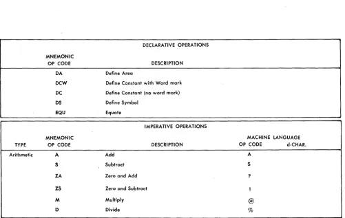
Several machine-language operation codes require operation modifiers (d-characters). With a few excep-tions, these d-characters are incorporated into Auto-coder mnemonics and do not have to be coded on the coding sheet. Thus, a single machine-language opera-tion code may have two or l ... lOre mnemonic equiv'\;
lents. For example, the machine-language Op code V
(TEST FOR WORK-j\,lARK OR ZONE AND BRANCH) has three mnemonic equivalents: BW (BRANCH IF WORD-MARK), BZN (BRANCH IF ZONE), and BWZ (BRANCH IF WORD-MARK AND/OR ZONE).
Operand (Columns 21-72)
The operand field in an imperative instruction contains the actual or symbolic addresses of the data, literals, or address constants, to be acted upon by the com-mand in the operation field. Address adjustment and indexing can be used in conjunction with these.
The Autocoder coding sheet has a free-form operand field. The A-operand, the B-operand, and the d-character must be separated by commas. If address adjustment or indexing or both are to be performed,
these notations must immediately follow the address being modified. Figures 3 and 4 show typical Auto-coder entries.
Comments
A comment can be included anywhere in the operand field of an Autocoder statement, if at least two spaces separate it from the last character of the operand.
Entire lines of information can be included any-where in the program by using a comments card. In such a card, containing comments only, the program-mer must put an asterisk in column 6. Columns 7-72 can then be used for the comment itself. Comments inserted in this way appear in the symbolic listing but produce no entry in the object program.
Identification (Columns 76-80)
This entry identifies a program or program section. This identification number. is printed on the output listing but does not appear in the object deck except as described in JOB. The areas labeled Program~
Pro-grammed By, and Date are for the conveniences of the user, but they are never punched.
DECLARATIVE OPERA liONS
MNEMONIC
OP CODE DESCRIPTION
DA Define Area
DCW Define Constant with Word mark
DC Define Constant (no word mark)
OS Define Symbol
EQU Equate
IMPERATIVE OPERA liONS
MNEMONIC MACHINE LANGUAGE
TYPE OP CODE DESCRIPTION OP CODE d-CHAR.
Arithmetic A Add A
5 Subtract S
ZA Zero and Add ?
ZS Zero and Subtract !
M Multiply @
0 Divide %
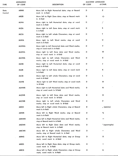
[image:4.620.39.540.374.691.2]TYPE
Data Control
MNEMONIC OP CODE
MRNR
MRZR
MLNA
MLZA
MLCA
MLWA
MLNWA
MLZWA
MLCWA
MLNB
MLZB
MLCB
MLWB
MLNWB
MLZWB
MLCWB
MRCR
MRWR
MRNWR
MRZWR
MRCWR
MRNG
MRZG
MRCG
IMPERATIVE OPERATIONS
DESCRIPTION
Move left to Right Numerical data; stop at Record mark in A-field
Move left to Right Zone data; stop at Record mark in A-field
Move right to Left Numerical data; stop at word mark in A-field
Move right to Left Zone data; stop at word mark in A-field
Move right to Left whole Characters; stop at word mark in A-field
Move right to Left Word marks; stop at word mark in A-field
Move right to Left Numerical data and Word marks; stop at word mark in A-field
Move right to Left Zone data and Word marks; stop at word mark in A-field
Move right to Left whole Characters and Word marks; stop at word mark in A-field
Move right to Left Numerical data; stop at word mark in B-field
Move right to Left Zone data; stop at word mark in B-field
Move right to Left whole Characters; stop at word mark in B-field
Move right to Left Word marks; stop at word mark in B-field
Move right to Left Numerical data and Word marks; stop at word mark in B-field
Move right to Left Zone data and Word marks; stop at word mark in B-field
Move right to Left whole Characters and Word marks; stop at word mark in B-field
Move left to Right whole Characters; stop at Record mark in A-field
Move left to Right Word marks; stop at Record mark in A-field
Move left to Right Numerical data and Word marks; stop at Record mark in A-field
Move left to Right Zone data and Word marks; stop at Record mark in A-field
Move left to Right whole Characters and Word marks; stop at Record mark in A-field
Move left to Right Numerical data; stop' at Group mark, word mark in A-field
Move left to Right Zone data; stop at Group mark, word mark in A-field
Move left to Right whole Characters; stop at Group mark, word mark in A-field
Figure 2. IBM 1410 Mnemonic Operation Codes (Continued)
MACHINE LANGUAGE OP CODE d-CHAR.
D Z
D
D
/
D S
D T
D U
D v
D W
D x
D
D K
D
D M
D N
D o
D P
D , (comma)
D %
D
D I (apostrophe)
D
D R
D
D $
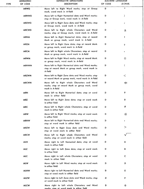
[image:5.612.81.563.77.710.2]TYPE
MNEMONIC OP CODE
MRWG
MRNWG
MRZWG
MRCWG
MRNM
MRZM
MRCM
MRWM
MRNWM
MRZWM
MRCWM
MRN
MRZ
MRC
MRW
MRNW
MRZW
MRCW
MLN
MLZ
MLC
MLW
MLNW
MLZW
MLCW
IMPERATIVE OPERATIONS DESCRIPTION
Move left to Right Word marks; stop at Group mark, word mark in A-field
Move left to Right Numerical data and Word marks; step at Group mark, word mark in A-field
Move left to Right Zone data and Word marks; stop at Group mark, word mark in A-field
Move left to Right whole Characters and Word marks; stop at Group mark, word mark in A-field
Move left to Right Numerical data; stop at record Mark or group mark, word mark in A-field
Move left to Right Zone data; stop at record Mark or group mark, word mark in A-field
Move left to Right whole Characters; stop at record Mark or group mark, word mark in A-field
Move left to Right Word marks; stop at record Mark or group mark, word mark in A-field
Move left to Right Numerical data and Word marks; stop at record Mark or group mark, word mark in A-field
Move left to Right Zone data and Word marks; stop at record Mark or group mark, word mark in A-field
Move left to Right whole Characters and Word marks; stop at record Mark or group mark, word mark in A-field
Move left to Right Numerical data; stop at word mark in either field
Move left to Right Zone data; stop at word mark in either field
Move left to Right whole Characters; stop at word mark in either field
Move left to Right Word marks; stop at word mark in either field
Move left to Right Numerical data and Word marks; stop at word mark in either field
Move left to Right Zone data and Word marks; stop at word mark in either field
Move left to Right whole Characters and Word marks; stop at word mark in either field
Move right to Left Numerical data; stop at word mark in either field
Move right to Left Zone data; stop at word mark in either field
Move right to Left whole Characters; stop at word mark in either field
Move right to Left Word marks; stop at word mark in either field
Move right to Left Numerical data and Word marks; stop at word mark in either field
Move right to Left Zone data and Word marks; stop at word mark in either field
Move right to Left whole Characters and Word marks; stop at word mark in either field
Figure 2. IBM 1410 Mnemonic Operation Codes (Continued)
MACHINE LANGUAGE OP CODE d-CHAR.
D *
D
D
D
D
D ?
D
D
o
D
D
<
D
D 9
D o
D #
D @
D
D
>
D
D A
D B
D C
D D
D E
D F
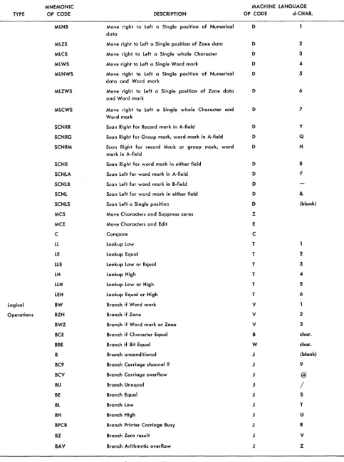
[image:6.621.49.542.64.713.2]IMPERATIVE OPERATIONS
MNEMONIC MACHINE LANGUAGE
TYPE OP CODE DESCRIPTION OP CODE d-CHAR.
MLNS Move right to Left a Single position of Numerical D data
MLZS Move right to Left a Single position of Zone data D 2
MLCS Move right to Left a Single whole Character D 3
MLWS Move right to Left a Single Word .mark D 4
MLNWS Move right to Left a Single position of Numerical D 5 data and Word mark
MLZWS Move right to Left a Single position of Zone data D 6 and Word mark
MLCWS Move right to Left a Single whole Character and D 7 Word mark
SCNRR Scan Right for Record mark in A-field D Y
SCNRG Scan Right for Group mark, word mark in A-field D Q
SCNRM Scan Right for record Mark or group mark, word D H mark in A-field
SCNR Scan Right for word mark in either field D 8
SCNLA Scan Left for word mark in A-field D if:
SCNLB Scan Left for word mark in B-field D
SCNL Scan Left for word mark in either field D &
SCNLS Scan Left a Single position 0 (blank)
MCS Move Characters and Suppress zeros Z
MCE Move Characters and Edit E
C Compare C
LL Lookup Low T
LE Lookup Equal T 2
LLE Lookup Low or Equal T 3
LH Lookup High T 4
LLH Lookup Low or High T 5
LEH Lookup Equal or High T 6
Logical BW Branch if Word mark V
Operations BZN Branch if Zone V 2
BWZ Branch if Word mark or Zone V 3
BCE Branch if Character Equal B char.
BBE Branch if Bit Equal W char.
B Branch unconditional J (blank)
BC9 Branch Carriage channel 9 J 9
BCV Branch Carriage overflow @
BU Branch Unequal J /
BE Branch Equal J S
BL Branch Low J T
BH Branch High U
BPCB Branch Printer Carriage Busy J R
BZ Branch Zero result J V
BAV Branch Arithmetic overflow J Z
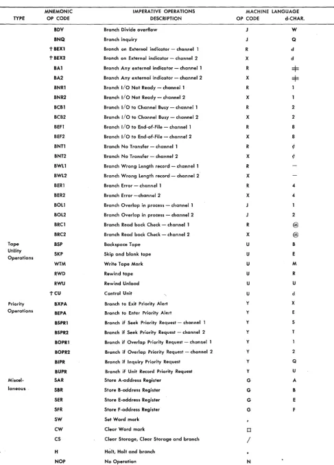
Figure 2. IBM 1410 Mnemonic Operation Codes (Continued)'
[image:7.615.81.565.74.724.2]MNEMONIC IMPERATIVE OPERATIONS MACHINE LANGUAGE
TYPE OP CODE DESCRIPTION OP CODE d-CHAR.
BDV Branch Divide overflow J W
BNQ Branch inquiry J Q
tBEXl Branch on External indicator - channel R d
'tBEX2 Branch on External indicator - channel 2 X d
BAl Branch Any external indicator - channell R =$= BA2 Branch Any external indicator - channel 2 X =$= BNRl Branch I/O Not Ready - channell R
BNR2 Branch I/O Not Ready - channel 2 X
BCBl Branch I/O to Channel Busy - channell R 2
BCB2 Branch I/O to Channel Busy - channel 2 X 2
BEFl Branch I/O to End-of-File - channell R 8
BEF2 Branch I/O to End-of-File - channel 2 X 8
BNTl Branch No Transfer - channell R ¢
BNT2 Branch No Transfer - channel 2 X ¢
BWLl Branch Wrong Length record - channel 1 R
BWL2 Branch Wrong Length record - channel 2 X
BERl Branch Error - channel 1 R 4
BER2 Branch Error -channel 2 X 4
BOLl Branch Overlap in process - channell
BOL2 Branch Overlap in process - channel 2 2
BRCl Branch Read back Check - channell R @
BRC2 Branch Read back Check - channel 2 X @
Tape BSP Backspace Tape U B
Utility
Operations SKP Skip and blank tape U E
WTM Write Tape Mark U M
RWD Rewind tape U R
RWU Rewind Unload U U
TCU Control Unit U d
Priority BXPA Branch to Exit Priority Alert Y X
Operations BEPA Branch to Enter Priority Alert Y E
BSPRl Branch if Seek Priority Request - channel y S
BSPR2 Branch if Seek Priority Request - channel 2 y T
BOPRl Branch if Overlap Priority Request - channel y
BOPR2 Branch if Overlap Priority Request - channel 2 y 2
BIPR Branch if Inquiry Priority Request Y Q
BUPR Branch if Unit Record Priority Request Y U
Miscel- SAR Store A-address Register G A
laneous SBR Store B-address Register G B
SER Store E-address Register G E
SFR Store F-address Register G F
SW Set Word mark
CW Clear Word mark 0
CS Clear Storage, Clear Storage and branch
/
H Halt, Halt and branch
[image:8.621.50.537.42.718.2]NOP No Operation N
TYPE
TYPE
I/O
Commands
MNEMONIC OP CODE
NOPWM
-r
CCMNEMONIC OP CODE
R P W RCP WCP WM RD RDT WD WDC WDT RT WT RTB WTB
IMPERATIVE OPERATIONS DESCRIPTION
No Operation Word Mark
Control Carriage
DESCRIPTION
Read card
Punch card
(n-character must appear in operand field of Auto-coder instruction)
Write a line
Read Console Printer
Write Console Printer
Write word Marks
Read Disk single record
Read Disk full Track
Write Disk single record
Write Disk Check
Write Disk full Track
Read Tape
Write Tape
Read Tape Binary
Write Tape Binary
NOTE: The preceding mnemonic Op Codes, except WM, may be followed by the letter W to indicate transfer of word marks and/or followed by the letter 0, including WM, to indicate overlapping.
T tAu T LU
RTG
RTBG
WTE
WTBE
SD
Move Unit Actual X-ADDR. and d-CHAR. must be coded in Autocoder instruction. Load Unit
Read Tape; stop only at interrecord Gap
Read Tape Binary; stop only at interrecord Gap
Write Tape; stop at End of core
Write Tape Binary; stop at End of core
Seek Disk
NOTE: Only the SD Mnemonic Op Code may be followed by the letter 0
to indicate overlapping. RTG, RTBG, WTE, WTBE can be followed by the letter W.
T SSF Select Stacker and Feed card
(d-character must appear in operand field of Auto-coder instruction)
MACHINE LANGUAGE OP CODE
N
F
d-CHAR
d
(Forms contror character)
MACHINE LANGUAGE X-ADDR
%In
%4n
(n denotes selected pocket) %20 %TO %TO %21 %F1 %F2 %F1 %F3 %F2 %Un %Un %Bn %Bn xxx xxx O/OUn %Bn %Un %Bn O/OFO
K (Op CODE)
d-CHAR. R W W R W W R R W W W R W R W d d $ $ X X R
b, 1,2 (denotes
selected pocket)
MNEMONIC
OP CODE DESCRIPTION
CONTROL OPERATIONS
MNEMONIC
OP CODE DESCRIPTION
CTL ORG LTORG EX END PST JOB Control Origin
Literal Origin
Execute
End
Print Symbol Table
Job Description
td-character must appear in operand field of Autocoder instruction
Figure 2. IBM 1410 Mnemonic Operation Codes (Continued)
Address Types
Six kinds of address types are valid in the operand field of an Autocoder statement: blank, actual, sym-bolic, asterisk, literals, and address constants.
Blank
A blank operand field is valid:
1. In an instruction that does not require an operand. 2. In instructions where valid A- and/or B-addresses are supplied by the chaining method. For example,
MLCA A,B l\1LCA
NOTE: If an instruction is to have addresses stored by other instructions, the operand or operands affected must not be left blank. For example, BOis recom-mended if the address of the branch instruction is to be supplied during the running of the object program.
Actual
[image:10.617.35.279.443.472.2]The actual core-storage address of a data field is valid in the operand field. High-order zeros in actual ad-dresses can be omitted as shown in Figure 3. Thus, an actual address can consist of from one to five digits. Figure 3 shows an imperative instruction that causes the contents of core-storage location 3101 to be added algebraically to the contents of location 140. This en-try will be assembled as a machine-language instruc-tion:
X
03101 00140. Note that high-order zeros can be eliminated when coding actual addresses for Auto-coder.Label OPi
~I,
Figure 3. Autocoder Instruction with Actual Addresses
Symbolic
A symbolic address can consist of as few as one or as many as ten alphamerical characters. Special char-acters are not permitted. Blank~ may not be written within a symbolic address. Figure 4 shows how sym-bolic addresses are used.
Figure 4 shows an indexed imperative instruction that causes the contents of the location labeled TOTAL to be placed in an area labeled ACCUM as modified by the contents of index location 2. An indexed address may be followed by a plus sign (+), an X to indicate indexing, and a number from 1 to 15 to specify which index location is to be used. TOTAL is the label for
Label opt
Figure 4. Autocoder Instruction with Symbolic Addresses
10
locations 3 1 Oland ACCUM is the label for location 1 4 O. The asse\pbled machine-language instruction for this entry is: D 03101 001MO C. The M in the tens position of the B-address is a 4-punch with an 11-. overpunch. The II-overpunch is the B-bit tag for in-dex location 2.
Asterisk (*)
If an '0 appears as an operand in the source program,
the processor will replace it in the object program with the actual core-storage address of the last character of the instruction in which it appears. For example, the instruction shown in Figure 5 is assigned core storage locations 00340-00351. The actual address of WKAREA is 00598. The assembled instruction is
D
00351 00598 C. When the instruction is executed in theob-. v
Ject program, D 00351 00598 C will be placed in WKAREA.
Asterisk operands can have address adjustment and indexing.
Label OPERAND
49 45 ~9 ,
:
Figure 5. Asterisk Operand in Autocoder Instruction
Literals
The IBM 1410 Autocoder permits the user to put in the operand field of a source program statement the actual data to be operated on by an instruction. This data is called a literal. The processor allocates storage for literals and inserts their addresses in the operand or operands of the instructions in which they appear. The processor produces a DCW card that puts a word mark in the high-order position of a literal when it is stored at program load time. Literals are permitted only in the operand field of an Autocoder statement and can be numerical or alphamerical. A literal can be up to 52 characters in length, including the sign; i. e., it must be contained in one line of the coding sheet, and it must not extend beyond column 72. Literal addresses may make use of address-adjustment and/or indexing.
Types of Literals
NUMERICAL LITERALS
Numerical literals are written according to the follow-ing specifications:
position of the number when it is assigned a storage location. NOTE: To store an unsigned number, use an alphamerical literal.
2. When a numerical literal does not exceed nine digits plus sign (blanks are not allowed), it is assigned a storage location only once per program or program section, no matter how many times it appears in the source program or program section. NOTE: A pro-gram section is defined as the source propro-gram entries that precede a Literal Origin, End or Execute State-. mentState-. In some programs several program sections
are needed because the entire object program ex-ceeds the total available storage capacity of the object machine. In these cases individual program sections are loaded into storage from cards, tapes, or random access storage and are executed as they are needed. Program sections are sometimes called overlays.
Figure 6 shows how a numerical literal can be used in an imperative instruction. Assume the literal (+ 10) is assigned a storage location of 00584 and 00585 and INDEX is assigned 00682. The symbolic instruction will cause the processor to produce a machine-language instruction
(A
00585 00682) that causes+
10 to be added to the contents of INDEX.Label
Figure 6. Numerical Literal
ALPHAMERICAL LITERALS
Alphamerical literals are written according to the fol-lowing specifications:
l. An alphamerical literal must be preceded and fol-lowed by the @. symbol. The literal itself can con-tain blanks, alphabetic, numerical,. and special characters (including the @ symbol). However, a comment on the same line as an alphamericalliteral must not contain the @ symbol.
Upon encountering an alphamerical literal, the processor proceeds to column 72 of the card and searches right to left for the terminal @ symbol. If it encounters any @ symbol, it will assume this is the legitimate terminal.
2. An alphamerical literal of from one to nine charac-ters with preceding and following @ symbols is assigned a storage location only once per program or program section no matter how many times it is used in the source program.
3. Longer alphamerical literals are assigned a storage location each time they are encountered in the source program. To save storage space in cases
where multiple use of long literals is necessary, use a DCW statement.
Figure 7 shows how an alphamerical literal can be used in an imperative instruction. Assume that the literal JANUARY 28, 1961, is assigned a storage location of 00906, and DATE is assigned 00230. The machine-language instruction
CD
00906 00230 C) causes the literal JANUARY 28, 1961 to be moved to DATE.Figure 7. Alphamerical Literal
AREA -DEFINING LITERAL
The 1410 Autocoder allows the user to define an area to be reserved by placing an area-defining literal in the operand field of a symbolic program entry as follows:
l. An area of any size may be defined in any instruc-tion which has as an operand the symbol which references it; for example, WKAREA#2.
2. A # symbol (8-3 punch) must precede the number that specifies how many core-storage locations are needed for the work area. Note that the # symbol is represented in the Fortran character set as an
=
symbol.3. A word mark is placed over the high-order position of the area.
4. If the user refers to a portion of the same defined area, such as WKAREA#6, he will be given a mul-tiple definition Hag in his output listing.
5. Address adjustment and indexing are permitted when using area-defining literals.
Figure 8 shows an imperative instruction with an area-defining literal. This entry causes the processor to allocate six storage locations for WKAREA. Six blanks will be loaded in storage at object program load time by a DCW card automatically produced by the proces-sor. Assuming that AMOUNT is in storage location 00796 and WKAREA is in 00596, the assembled
machine-la~uage instruction that moves AMOUNT to WKAREA is D 00796 00596 C.
Label
ADDRESS CONSTANT LITERALS
The actual 5-character machine address which is as-signed to a label by the processor can be defined as an address constant. Autocoder permits address constants to be coded symbolically in the instructions that re-quire them:
1. The symbol for an address constant can contain as many as ten characters.
2. A plus sign must precede the symbol. The address constant is the actual address which was assigned to the label by the processor.
3. The label being defined must appear elsewhere in the symbolic program.
4. The address constant is assigned a core-storage ado: dress, as are all constants, and a DCW card is created
automatically by the processor. The address con-stant literal is unsigned in core storage.
NOTE: If address adjustment and indexing occur,
they modify the address of the literal, not the literal itself.
Figure 9 shows how an address constant literal can be used. Assume that CASH is used as a label elsewhere
in the program and has been assigned a machine ad-dress of 00600. The adad-dress constant (00600) has been assigned storage location 00797. The first character in
the second instruction is in core storage at address 00401. Thus, the address of INST
+
5 is 00406.II ISIS I 2 5 9 5 9
~ L~I
t" ..
~
OPERANDNs~
:
i : ::£2:
1:~~~~~~+::
: :: : : : ;: : : : :: : : : :
Figure 9. Address Constant
The assembled machine-language instruction for the v first symbolic instruction in Figure 9 is D 00797 00406
C.
WORK is in storage location 00729. The assembled
ma-chine-language iI~struction for the second symbolic pro-gram entry is D 00000 00729· C. When the first instruction is executed in the object program, the con-stant 00600 is moved to 00406 and the second instruc-v tion becomes D 00600 00729 C. When the ·second instruction is executed, the contents of CASH are moved
to WORK.
Thus, the programmer can write an instruction that will move a machine address into the operand of an-other instruction at program execution time, even though he does not know what that address is.
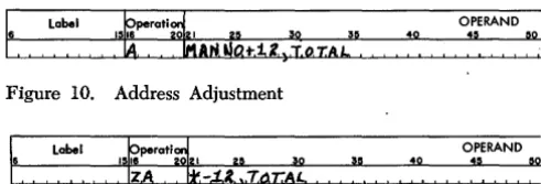
Address Adjustment
Address adjustment is valid in the operand field on all symbolic addresses, including the asterisk. It enables the programmer to refer to an entry in his source pro-gram that is a specified number of locations away from
Label
49
Figure 10. Address Adjustment
Label ~perati~
151 I 39
ZA
Jt-il;
7.t1r:AL49
OPERAND
:~ , ~9
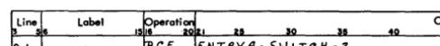
Figure 11. Address Adjustment with an Asterisk Operand
a symbolic address. Its usage reduces the number of symbolic labels required. Address adjustment is indi-cated by writing after the symbolic address a plus or minus sign followed by one to five digits (Figure 10). When the label MANNO is assigned location 05000
and TOTAL is assigned the location 00075, the
assem-bled instruction is
X
05012 00075.If the instruction in Figure 11 is assjgned the ad-dress 05000, the assembled instruction. is
?
04998 00075, because 0 refers to the rightmost position of thein-struction (05010). When using address adjustment, the programmer should remember that insertions or de-letions in the source program can affect adjustment addresses.
Index Registers
Indexing is accomplished by tagging an address in the operand field with an indicator telling the processor which i,ndex register is to be used. The mM 1410 sys-tem has 15 index registers that can be referred to in Autocoder language by placing an X before their num-ber. Thus, XI0 denotes index register 10. The X en-ables the processor to distinguish between address adjustment and indexing.
An index register can also be referred to symboli-cally. XO through X15 are not acceptable as symbolic names. The index label must be preceded by a plus. It follows the operand address and the address adjust-ment, if any. Figure 12 shows an example of indexing.
The contents of the location with the address,
MANNO plus the contents of index register 2, is
alge-braically added to the contents of location 00400. For example, if the label MANNO is assigned location
05000 and index register 2 contains 500, then the pre-ceding instruction causes the contents of location 05500 to be added to the contents of location 00400.
Label ~perati~
49
OPERAND
:~ ~9
,
:
[image:12.617.298.544.64.147.2]Indexing is not acceptable in DS, ORC, or LTORC
declara-tive operations nor control operations.
An index register can be specified in the operand field for other than indexing purposes. For example, a numerical value can be added to the contents of an index register. In this case, the index register may be referred' to by its actual label (Xl, X2, etc.) or its symbolic label (see EQU).
Index
Register Reservation
The processor assigns index registers referred to in the symbolic program.
Those index registers that are coded in actual no-tation (Xl, X2, etc.) and those equated to a symbolic address by an EQU statement are assigned first. Then the remaining index registers are assigned to symbols the programmer has used to represent index registers. For example, the programmer may use the symbolic instruction shown in Figure 13.
In this case, CONST is the symbolic label for an index
register. Its contents will modify the address assigned to the label (WHTAX). The instruction in Figure 13 may
be followed by the instruction shown in Figure 14. This instruction puts the numerical value 25 in the index register which the processor assigns to CONST.
Autocoder Coding Examples
Figure 15 shows an imperative instruction with 'ild-dress adjustment and indexing on a symbolic ad'ild-dress. The processor will subtract 12 from the address as-signed the label TOTAL. The effective address of the
A-operand is the sum of TOTAL -12 plus the sontents
of index location 1. The assembled instruction D 030Y9 00140 C will cause the contents of the effective address of TOTAL -12 +X1 to be placed in the location
la-beled ACCUM (assuming again that TOTAL is the label
Label
~
perati4 OPERAND1516 ~ ~ 30 3~ 40 :~ ~o
Figure 13. Symbolic Label for an Index Register
Label OPERAND
40
:~ ! ~o
Figure 14. Using the Symbolic Label Label
Figure 15. Autocoder Instruction with Address Adjustment and Indexing
for location 3 1 Oland ACCUM is the label for location
1 4 0). The Y in the tens position of the A-address is an 8-punch with a zero overpunch. The zero over-punch is a tag for index location 1.
NOTE: Address adjustment and indexing are
per-mitted in the same operand. Multiple address adjust-ment causes the algebraic sum of the factors to be used. With multiple indexing, only the rightmost in-dex notation is effective. For example:
A TOTAL +3 +X1 -12 +X2, ACCUM -5 +X2 +35
will be interpreted as:
A TOTAL -9 +X2, ACCUM +30 +X2
which is equivalent to:
A TOTAL +X2 -9, ACCUM +X2 +30
Figure 16 is an imperative instruction with two sym-bolic operands and a d-character. Although many of the augmented operation codes available for use with Autocoder eliminate the need to write the d-character in a symbolic instruction, sometimes the d-character must be specified by the programmer. If an instruction requires such a specified d-character, it is written fol-lowing the A- and B-operands and is separated from the remainder of the instruction by a comma. The v assembled machine-language instruction is: B 00392 00498 2. It branches to ENTRY A (00392) if the location
labeled SWITCH contains a 2.
Label OPI
:~
Figure 16. Autocoder Instruction with ad-Character
Declarative Operations
A program for the 1410 usually requires the use of work areas and constants. A work area is a portion of storage into which data is transferred for processing. It can be used for the accumulation of totals or for the assembling of data to be printed out or punched into cards. A constant is a fixed quantity or item of information that is required again and again or that must remain the same throughout the course of the program. For example, a date can be considered a constant.
The use of Autocoder enables the programmer to refer to work areas and constants by their descriptive names without regard to their actual location in core storage. For example, assume that the programmer wants to reserve twenty consecutive core locations for accumulating a final sales total. A declarative opera-tion enables the programmer to reserve such an area and to refer to it by a symbolic label without concern-ing himself with the actual address of the field.
[image:13.620.332.576.404.430.2] [image:13.620.73.317.531.702.2]Declarative operations are definitions rather than instructions. As such they are acted upon during as-sembly but are not executed during the running of the object program. For this reason the programmer should keep declaratives separate from imperatives (machine instructions) when writing the symbolic pro-, gram. If they are placed in the body of the program,
care must be taken to branch around them so they will not be treated as instructions.
The mM 1410 Autocoder provides five different declarative operations for reserving work areas and storing constants:
OPCODE
DCW DC DS DA
EQU
PURPOSE
Define Constant with Word Mark Define Constant (no word mark) Define Symbol
Define Area Equate
DCW - Define Constant with Word Mark
General Description: A DCW statement is used to enter a numerical, alphamerical, or address constant with a word mark into a core-storage area. Symbolic la-bels address the low-order position of the constant. Word marks are set in the high-order positions of all constants. If a symbolic label is indented one posi-tion, the address of the high-order position of the constant will be assigned to the symbol. Actual la-bels always refer to the high-order position of the defined constant.
The programmer:
1. Writes the operation code (DCW) in the operation field.
2. May write an actual or symbolic label in the label field. The programmer may refer to the constant later by writing this label in the operand portion of subsequent instructions.
3. Writes the constant in the operand field beginning in column 21.
NUMERICAL CONSTANTS
1. A numerical constant can be preceded by a plus or minus sign. A plus sign causes AB-bits to be placed over the units position of the constant; a minus sign causes a B-bit to be put there. If a numerical constant is unsigned in the DCW statement, it will be stored as an unsigned field.
2. The first blank column appearing in the operand field terminates a numerical constant.
40
Figure 17. Numerical Constant Defined in a Dew Statement
3. The maximum size of a numerical constant is 51 digits and a sign, or 52 digits with no sign.
Example: Figure 17 shows the number
+
10 defined as a numerical constant. The address of the constant will be inserted in the object instruction wherever TEN appears in the operand field of another symbolic instruction.ALPHAMERICAL CONSTANTS
1. An alphamerical constant must be preceded and followed by the @ symbol. Blanks and the @ sym-bol can appear within an alphamerical constant, but the @ symbol cannot appear in a comment on the same line as an alphamerical constant.
2. The alphamerical constant itself can be as large as 50 characters.
3. If no terminal @ is present, a 51-character constant will be produced.
Example: Figure 18 shows the alphamerical constant, JANUARY 28, 1961, defined in a DCW statement. The address of the constant will be inserted in the ob-ject program instruction wherever DATE appears in the operand field of another symbolic program en-try.
NOTE: A comma G following the trailing @ symbol of an alphamerical constant causes the processor to put a group-mark word-mark in storage following the last character of the constant. The associated label, if
any, will refer to the last character of the constant, not the group-mark word-mark.
h
Lobel~Tf.
:i
peroti~
1516 021 ~ 3:' 3: ~
Figure 18. Alphamerical Constant Defined in a Dew Statement BLANK CONSTANTS
A
#
symbol precedes a number indicating how many blank storage positions are to be defined. This permits the programmer to reserve a field of blanks with a word mark in the high-order position of the fi'eld. Maximum size of this field is limited only by the available storage capacity.Example: Figure 19 shows an II-character blank field defined by a DCW statement. The address of this blank field will be inserted in an object program in-struction whenever the symbol BLANK appears as the operand of another symbolic program entry.
~ Line
J
Label'o I.
bik.d
tiK,~perati~
15~
J
~5OPi
:~
CW 11..
ADDRESS CONSTANTS
An address constant can be preceded by a plus or a minus sign, or it can be left unsigned. The constant is the actual machine-language address of the field whose associated label is included in the operand. The units position of the constant will have the sign which the user placed before the operand.
NOTE: Address constants may be address adjusted and indexed.
Example: Figure 20 shows an address constant (the address of MANNO) defined by a DCW statement. The
address of the address constant MANNO will be
in-serted in an object program instruction whenever
SERIAL appears as the operand of another symbolic
program entry.
~L1ne~ Label
0, I j;,ER {A.L
Figure 20. Address Constant Defined by a Dew Statement
DC - Define Constant (No Word Mark)
OPI
General Description: This statement has the same characteristics as the DCW statement. The only
dif-ference is that the processor does not cause a word mark to be set at the high-order position of the con-stant when the concon-stant is produced in the object deck.
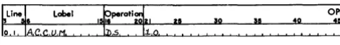
DS - Define Symbol
General Description: A DS statement reserves and
labels an area. of core storage. It differs from a DCW
or DC statement in that no information (constant) is
loaded into this area at program load time. The programmer:
1. Writes the operation code (DS) in the operation field.
2. May write a symbolic address in the label field. 3. Writes a number in the operand field to indicate
how many storage positions are to be reserved.
The processor:
1. Assigns an actual address to the low-order position of the reserved area.
2. Inserts this address in the instruction wherever the symbol in the label field appears in the operand field of another symbolic program entry.
Example: Figure 21 shows how a 10-position core-storage area can be reserved. The programmer can
e
Label~
perati915_ _II ~'
OPI
:~
Figure 21. DS Statement
refer to the label by putting ACCUM in the operand
field of another symbolic program entry.
DA - Define Area
General Description: DA statements reserve and define
portions of core storage, such as input or output or work areas. They can also define more than one area, if all these areas are identical in format. A DA
statement differs from a DCW statement in that a DA statement can, in addition to defining the large
area, also define several fields within it. The DA
statement furnishes the processor with the lengths, names, and relative positions of fields within the defined area.
HEADER LINE
The programmer constructs a header line for the DA
entry as follows:
1. Writes the operation code (DA) in the operation
field.
2. May write an actual or symbolic address in the label field. This address represents the high-order position of the entire area defined by the DA
state-ment.
3. Indicates in the operand field the required size of the area in the form B X L. B is the number of identical areas to be defined and L is the length of each area. For example, if four identical areas, each 100 characters long, are to be defined, the first entry in the operand field is 4 X 100 as shown in Figure 22. If only one area is to be defined, the first entry is 1 X 100.
opt
01 L.4PE.4B ~!!.
49
Figure 22. Four Areas Defined
Indexing: To index a DA statement place a comma
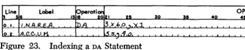
and the number of the index location (Xl, X2, X3, etc.) after the B X L indication. All labels in the en-tries following the header line will be indexed by the specified index register when they appear in instruc-tions, unless the instruction referring to the field is itself indexed. For example, if IN AREA is defined by
the statement shown in Figure 23, ACCUM is indexed
by index location l. If the entry shown in Figure 24 appears as an instruction elsewhere in the program,
ACCUM (for this instruction only) will be indexed by
[image:15.615.339.581.67.99.2]OPI
Figure 23. Indexing a DA Statement
the contents of index location 2. Because the instruc-tion in Figure 24 has indexing, this indexing overrides the indexing prescribed by the DA statement.
NOTE: The programmer can negate the eHect of indexing on a field or subfield by putting an XO in the operand field of each instruction in which indexing is not wanted. Symbolic names for index registers may be specified in the heading line of a DA statement only
if previously defined by an EQU statement.
Record Marks: Record marks can be inserted to separate records in the defined area. The processor will cause a =1= to be placed in storage immediately following each identically defined area if a comma =1=
follows the B X L entry in the operand field. B X L does not include an allowance for the record mark. For example, 2 X 100 will cause 200 positions to be reserved for the defined area, but 2 X 100, =1= will cause 202 positions to be reserved.
Group Mark with Word Mark: The user can cause the processor to put a group mark with' a word mark one position to the right of the entire defined area by writing a G, preceded by a comma in the operand field.
Relative to Zero Addressing: By writing a comma zero after the B X L entry, the user can cause the processor to assign addresses to the labels of fields and sub-fields as though the high-order position of the de-fined area was core-storage location zero. The label of the DA statement is assigned the address of the
high-order position of the area actually reserved by the processor.
NOTES
1. A user of 1410 IOCS must define areas to be used for blocked records using indexing, with relative to zero addressing.
2. The programmer may write the =1=, index code, G and 0 entries in any order in the operand field of the DA header statement provided that they follow
the B X L entry.
OTHER DA ENTRIES
The programmer constructs the balance of the DA
statement which defines fields and subfields for each area as follows:
1. Leaves the operation field blank.
Label ~perati9
15L A~ B Q ::~ fA c,c~Ji -t X fe3! Figure 24. Overriding Indexing in a DA Statement
16
40 OPI
45
2. Writes a symbolic label in the label field if one is desired.
3. Specifies the relative location of defined fields with-in the area by puttwith-ing two numbers with-in the operand field. The first location of the defined area is con-sidered location 1. The high-order and low-order positions of the field are written beginning in col-umn 21. These two numbers must be separated by a comma.
4. A subfield is a field within a defined field and is defined by putting the number representing the low-order position in the operand field.
NOTES: The processor causes word marks to be set in the high-order position of each defined field, but does not so identify subfields. If a word mark is desired in a one-position field, the relative position number must be written twice with the two numbers separated by a comma.
Fields defined in a DA statement can be listed in any
order, and all positions within the defined area do not have to be included in the defined fields.
The processor:
1. Allocates an area in core storage equal to B X L plus positions for record marks and a group mark if they are specified in the heading line of the DA entry
and -assigns actual addresses to the defined fields and subfields.
2. Inserts the assigned address of the high-order posi-tion of the entire defined area wherever the con-tents of the heading line label field appear as the operand of another symbolic program entry.
3. Inserts the assigned addresses of the low-order po-sitions of defined fields and subfields in the place' of symbols corresponding to the labels of the field-defining entries.
Result: At object program load time:
1. Word marks are set for field definition as noted previously.
2. A group mark and record marks are loaded as speci-fied in the heading line.
Example: In this example, data is to be read from magnetic tape into an area of storage where it is to be processed. It is a payroll operation, and each rec-ord refers to a different employee. The recrec-ords are written on tape in blocks of three. Each record is eighty characters long and has the following format:
Positions 4-8 Man Number Positions 11-26 Employee Name Positions 32-37 Date
Positions 45-64 Gross Wages Positions 66-71 Withholding Tax Positions 74-79 FICA Deduction
[image:16.615.34.276.61.111.2]month within the date, will be defined as a subfield. A group mark with a word mark is to be placed in storage immediately following the third area.
The DA statement in Figure 25 defines three adjacent identical areas into which each block of three records will be read. It also defines the fields and subfields that are to receive the data listed. The notation 3 X 80 in the header line indicates that three consecutive areas of eighty locations each are to be reserved. The entire 240-location area can be referred to by its high-order label, RDAREA. The G in the header line will cause a group mark with a word mark to be placed in the 241st position. The reference to index location 2 in the header line indicates that the labels NAME, MANNO, DATE, GROSS, FICA and MONTH, when referred to in symbolic instructions, will be indexed by index location 2.
The IOCS will give an instruction to read data from tape into a storage area labeled RDAREA. This causes a block of three data records to be placed in the 240 reserved core locations. As a result, the significant data is read into the appropriately labeled fields. This data can now be referred to via the labels DATE, MANNO, FICA, etc., and the user need not concern himself with actual machine addresses. In this example, the IOCS begins by setting index location 2 to the address of the input area. The user then processes the significant data in the first record. The subsequent GET macro will increment index location 2 by eighty, and the user can branch back to the first instruction of the particular routine. Because all labels defined by this DA statement are incremented by the contents of in-dex location 2, the program will now be processing the second record read into storage. \Vhen this routine is performed three times, the user has processed three input records and is ready to read three more records into storage. This lias all been performed without any reference to actual machine addresses.
NOTES:
1. An area can be reserved for a record with variable fields by defining all possible fields as subfields. In this case, no word marks will be set in an individual area, but the programmer can control data transfer by setting word marks in the receiving fields.
Figure 25. DA Statement
2. If the length of the whole record can also vary, the programmer should reserve an area equal to the largest possible record size.
EQU - Equate
General Description: An EQU statement assigns a sym-bolic label to an actual or symsym-bolic address. Thus, the user can assign different labels to the same storage location in different parts of his source pro-gram.
The programmer:
1. Writes the operatiQn code (EQU) in the operation field.
2. May write a symbolic address for the new label in the label field.
3. Writes an actual or symbolic address in the operand field. This address can have indexing and address adjustment.
The processor:
1. Assigns to the label of the equate statement the same actual address that is assigned to the symbol in the operand field (With appropriate alteration if indexing and address adjustment are indicated). 2. Inserts this actual address wherever the label
ap-pears as the operand of another symbolic program entry.
Result: The programmer can now refer to a storage location by using either name.
Examples: Figure 26 shows the label INDIV equated to MANNO which has been assigned storage location 01976. Whenever either MANNO or INDIV appear in a symbolic program, 01976 will be used as the actual address.
Figure 27 shows an equate statement with address adjustment. If FICA is assigned location 00890, WHTAX will be equated to FICA-I0 (00880). WHTAX now refers to a field whose units position is 00880.
Figure 28 shows a label assigned to an actual ad-dress. Assume that an input card contains NETPAY in card columns 76-80. When this card is read into stor-age, the area locations 01076-01080 contain net pay
Figure 26. EQU Statement
~Line
I
Labelo
I 5~,!U ~')(,~
perati~
151 ~~!!, ~o
Figure 27. Address Adjustment in an EQU Statement
OPI
:~
OPI
45
[image:17.618.79.325.634.712.2](if the read area is 01001-01080). This field can be re-ferred to as NETP A Y if the EQU statement in Figure 28
is written in the source program.
Figure 29 shows how an equate statement can be indexed. With indexing, the label is indexed by the index location specified in the EQU statement,
when-ever it appears as an operand in a symbolic program entry, unless the operand in which it appears is itself indexed. In Figure 29, the address assigned the sym-bolic label CUSTNO is equated to the actual address
of JOB
+
the contents of index location 3. However, if CUSTNO+
X2 or CUSTNO+
Xl appear as the operandof another symbolic program entry, the actual address of JOB will be added to the contents of index location 2
or l. Thus, the indexing in an instruction takes prece-dence, and index register 3 is ignored.
Figure 30 shows the symbol FIELDA equated to an
asterisk address. The asterisk refers to the current position of the processor assignment counter. (This will be the first position of the instruction or data to be next assigned.) Assume that this address is 00698.
FIELDA is now equal to 00698.
Figure 31 shows how a label can be assigned to an index location. The operand contains a number from 1 to 15, followed by a comma, followed by the letter X to indicate the specific index register. INDEX 1 is now
equal to 00029. Figure 31 also shows an alternative method for equating a label to an index register.
Figure 32 shows how a tape unit can be assigned a label. In this case, the programmer wishes to refer to tape 4 on channell as INPUT.
A tape unit may also be equated to a symbolic name by using the actual X-control field (for example
% U 4) as the operand, as shown in Figure 33.
~ Label
40
OPERAND
45. , ~o 30
Figure 28. Assigning a Label to an Actual Address
~ Line
I
Labelo
I'~~'U.S TN.Q40
Figure 29. Indexing an EQU Statement
~Line~ Label 49
Figure 30. Equating with an # Operand
Figure 31. Assigning a Label to an Index Location
18
I
Label 151 ~peratl~ I 2 51! 40Figure 32. Assigning a Label to a Tape Unit
Figure 33. Actual X-Control Field
Imperative Operations
General Description: Autocoder imperative opera-tions are direct commands to the object computer to act upon data, constants, auxiliary devices, or other instructions. These are the symbolic state-ments for the instructions to be executed in the' object program. Most of the statements written in a source program will be imperative instructions. Although the Autocoder processor can assemble in-structions with all the imperative operation code mnemonics which are shown in Figure 2, the pro-grammer must remember the particular special fea-tures and devices that will be included in the object machine that will be used to execute the program he is writing.
The programmer:
1. Writes the mnemonic operation code for the in-struction in the operation field.
2. If the instruction is an entry point for a branch in-struction elsewhere in the program or if the pro-grammer wishes to make other reference to it, it should have a label. This label will be assigned an actual address equal to the address of the operation code of the assembled machine-language instruc-tion. Thus, the programmer can use this label as the symbolic I-address of a branch instruction else-where in the program (see Example, Figure 41). 3. Writes the symbolic address of the data, devices, or
constants in the operand field. The first symbol will be used as the A- or I-address of the imperative instruction. If the instruction also requires a B-address, a comma is written following the first sym-bol and its address adjustment and/or indexing codes (if any), then the symbol for the B-address is written. If the instruction requires that ad-character be specified, a comma and the actual d-character follow the symbolic entries for the B-address or an I -address if the B-address is not needed.
NOTES
of coding the d-character in the operand field of sym-bolic imperative instructions. However, some opera-tion codes have so many valid d-characters that it is impractical to provide a separate mnemonic for each. In these cases, the programmer supplies the d-character as previously described. In the listing of mnemonic operation codes for imperative instructions (Figure 2) all mnemonics which require that the d-character be included in the operand field are indi-cated by a
t.
Coding
Figure 34 shows a brief routine illustrating a section of Autocoder coding. Note that remarks can appear any-where in the operand field, provided at least two blank spaces separate the remarks from the operand of the instruction.
Several imperative operations are governed by spe-cial rules, and care must be taken when coding with these instructions. The special cases are described in the following paragraphs.
Data-Move Instructions
The data-move command is controlled in machine v language by the Op code D. The actual conditions of the various types of data move instructions are regu-lated by the d-character. To make the Autocoder lan-guage more meaningful, each of these move and scan instructions has a different mnemonic op code. Each of these mnemonics specifies the type of operation, the direction of the move or scan, the nature of the data to be moved, and what terminates the operation. The following rules apply in constructing the mne-monics for data-move commands:
Itt ove Mnemonics
1. The first character of the mnemonic is M.
2. The second character specifies the direction of data movement.
L - Right-to-Ieft movement. R - Left-to-right movement.
Label 1~~perati~121
6 25 ~O
1,U )C (DJ~
n5 I IH!. '<I. ~1.@
S.T,A.R,T I :;',\J. 1181
I ~. '1. 10,1 I
RAI E,RRO.R.
I B.Z,JI, P.R. I NT.,l.B.o ,B
1 p ~"lQj
I
B,A1. E.~/(.o.R.
I
'A. STAR T. PKIN.T, I ro.'-I. 11,21
I
IJ 1 a1
I
lila FRR.o.R. ~ STA.R.T.
I
CN.o ~,TA.R.T.
Figure 34. Autocoder Coding
OPERAND
55 40 45 50
3. The third section of the mnemonic specifies the por-tion of data moved.
N - Move numerical portion of data. Z - Move zone portion of data. C - Move whole characters. W - Move word marks.
NW - Move numerical portion and word marks. ZW - Move zone portion and word marks. CW - Move whole characters and word marks. 4. The final character of the mnemonic specifies what
terminates the move.
a. To terminate right-to-Ieft move: A - Word mark in A-field. B - Word mark in B-field.
(Blank)- Word mark in either field. S - Move single location only.
b. To terminate left-to-right move: R - Record mark in A-field.
G - Group mark with a word mark in A-field. M - Record mark or group mark with a word mark in A-field.
(Blank) - Word mark in either field. Scan Mnemonics
1. The first three characters are always SCN.
2. The fourth character specifies the direction of scan. L - Right-to-Ieft scan.
R - Left-to-right scan.
3. The fifth character specifies what terminates the scan.
a. To terminate right-to-Ieft scan: A - Word mark in A-field. B - Word mark in B-field.
(Blank) - Word mark in either field. S - Scan left single position.
b. To terminate left-to-right scan: R - Record mark in A-field.
G - Group mark with a word mark in A-field. M - Record mark or group mark with a word mark in A-field.
(Blank) - Word mark in A- or B-field.
For example, when whole characters and word marks are to be moved from right to left, terminating the move on a word mark in the A-field, the Autocoder mnemonic op code is MLCWA.
A complete list of these data. move mnemonics is included in the List of 1410 Autocoder Mnemonic Operation Codes (see Figure 2).
I'
Label.
:
OPERAND:~
:
[image:19.617.73.319.485.708.2]SSF - Select Stacker and Feed
This instruction causes the last card transferred to storage to be selected into the stacker specified in the operand field of the instruction., A blank operand causes the card to be selected into the zero read pocket. A 1 in the operand field causes the card to be selected into stacker 1. A 2 in the operand field causes the card to be selected' into stacker 8/2.
Magnetic Tape Commands
Mnemonics referring to magnetic tape do not require d-characters. However, it is necessary to specify, in the operand, the number of the tape unit and chan-nel needed for the operation. This can be done in one of three ways.
The programmer can:
l. Assign a label to the channel and tape unit as de-scribed in EQU and use it as the A-operand of a
tape instruction, or
2. Write the number of the channel and tape unit in columns 21 and 22 of the tape instruction. The as-sembled instruction for the symbolic entry shown in Figure 35 will cause a record to be written on tape unit 4 using the data beginning in a storage area labeled OUTPUT, or
3. Write the X-control field as the A-operand of the tape instruction.
Disk Commands
All input-output commands involving disk units must specify the channel (1 or 2) as the first entry of the operand field. If an address is used in the operand, it follows the channel designation and is separated from it by a comma as shown in Figure 36.
BZN - Branch on Zone
The operand of this command takes the form I ADDR,
Ch where:
Ch = Zone configuration to be tested for (A, B, AB, blank, - ,
+,
or ¢)ADDR = Address of character whose zone is to be
tested.
I = Address to branch to
ADDR or both addresses can be omitted if this
opera-tion is chained. Acceptable forms of this operaopera-tion are:
label
BZN I, ADDR, Ch
BZN I
BZN
Figure 36. Disk Storage Instruction
20
OPERAND
40
:~ , ~o
BWZ - Branch if Word Mark, Zone, or Both
This operation is the same as BZN except that a branch
also takes place if a word mark is present.
BCE - Branch if Character Equal
The operand o