Systems Reference Library
Miscellaneous Input/Output Instructions
IBM 1401. Data Processing System
IBM 1460 Data Processing System
This publication contains a description of the instructions used by the IBM 1401 or 1460 to operate
these miscellaneous input/output units:
IBM 1009 Data Transmission Unit IBM 1404 Printer
IBM 1407 Console Inquiry Station IBM 1418 Optical Character Reader IBM 1428 Alphameric Optical Reader IBM 1412 Nlagnetic Character Reader IBM 1419 Magnetic Character Reader IBM 1448 Transmission Control Unit IBM 1026 Transmission Control Unit IBM 1231 Optical Mark Page Reader IBM 1285 Optical Reader
IBM 1445 Printer
IBM 7740 Communication Control System IBM 7770 Audio Response Unit, Modell
Timing information is included for each unit attached to an IBM 1401 or 1460 Data Processing System.
Preface
This publication is a portion of the reference text for the IBM 1401 and 1460 Data Processing Systems. The
full set of manuals provides a detailed explanation of all the instructions used by the system to manipulate data. Detailed explanations of the instructions used with the required and available input/output units at-tached to the system are also included. The reader should be familiar with the IBM 1401 System Sum-mary, Form A24-1401, or the IBM 1460 System Sum .. mary, Form A24-1496, and the various publications on programming material, such as Symbolic Programming System (SPS) and Autocoder.
The complete manual is divided functionally into these sections:
System Operation Reference Manual (A24-3067) Section A
Section B Section C Section D Section E Section
J
Section KIntroduction System Operations
IBM 1406 Operations IBM 1447 Operations
IBM 1402 and 1403 Operations
Index of Instructions Consolidated Index
Major ReVision, November 1964
This publication, Form A24-3068-1, is a major revision of A24-3068-0, however it does not obsolete the previous publica-tion, nor Technical Newsletter N24-0195 which it includes. The added material covers the new input/output units:
IBM 1026 Transmission Control Unit IBM 1231 Optical Mark Page Reader
IBM 1285 Optical Reader
IBM 1445 Printer
IBM 7740 Communication Control System
IBM 7770 Audio Response Unit, Model 1
Refer to the IBM 1401 and 1460 Bibliography, A24-1495, for other publications.
Tape Input/Output Instructions (A24-3069) Section F Tape Input/Output Operations Disk Input/Output Instructions (A24-3070)
Section G Disk Input/Output Operations Miscellaneous Input/Output Instructions (A24-3068)
Section H Miscellaneous Input/Output Oper-ations
Special Feature Instructions (A24-3071) Section I Special Feature Operations
The sections are independent and do not have to be used in the order in which they appear. A System Reference Library can be compiled using those sec-tions applicable to the user's machine configuration.
This publication is intended for programmers and systems personnel who have a general knowledge of the IBM 1401 or 1460 Data Processing Systems and who
require a reference text for detailed information. Other publications referenced here are, in most cases, prerequisites for a complete understanding of the material presented in this publication.
Copies of this and other IBM publications can be obtained through IBM Branch Offices.
Contents
Miscellaneous Input/Output Instructions ... H-1
IBM 1009 Data Transmission Unit ... H-1
IBM 1401 or 1460 Programming Logic ... H-1 IBM 1009 Instructions ... H-3 IBM 1404 Printer ... H-7 IBM 1404 Instructions ... H-7 IBM 1407 Console Inquiry Station ... H-lO IBM 1407 Instructions ... H-10 IBM 1418 Optical Character Reader ... H-13 IBM 1418 Instructions ... H-13 IBM 1428 Alphameric Optical Reader ... H-16 IBM 1428 Instructions ... H-16 IBM 1401 or 1460 with 1418 or 1428
General Block Diagram ... ... ... H-20 Programming Considerations ... H-22
IBM 1412 Magnetic Character Reader Model 1 H-26 IBM 1412 Instructions ... H-26 IBM 1412 Programming Considerations ... H-32 IBM 1412 Timings ... H-35 IBM 1419 Magnetic Character Reader ... H-38 IBM 1419 Instructions ... H-38 Read Instructions ... H-38 Miscellaneous Instructions ... H-44
IBM 1448 Transmission Control Unit ... H-48 IBM 1448 Instructions ... H -49 Direct Data Channel Interrupt ... H-53
IBM 1026 Transmission Control Unit ... H-55 IBM 1231 Optical Mark Page Reader ... H-56 IBM 1231 Instructions ... H-56 IBM 1231 Program Control... H-57 IBM 1285 Optical Reader ... ... ... ... H-61 IBM 1285 Instructions ... H-61 Overlap Operations (1285) ... H-63 Timing Considerations (1285) ... H-63
IBM 1445 Printer for the 1401 System ... H-63 IBM 1445 Printer Instructions for 1401 ... H-63 IBM 1445 Printer for the 1460 System ... H-65 IBM 1445 Printer Instructions for 1460 ... H-65 Multiple Printer Output for the 1460 System
Using the 1445 Printer ... '... H-66
IBM 7740 Communication Control System ... H-67 IBM 7740 Instructions ... H-67 IBM 7770 Audio Response Unit Modell... H-69 IBM 7770 Instructions ... H-70 IBM 7770 Model 1 Programming ... H-70
IBM 1009 Data Transmission Unit
The IBM 1009 (Figure H-1) permits high-speed 2-way
communication between two IBM 1401 or 1460 Data
Processing Systems:
• A 1401 and a 1460 Data Processing System
• A 1401 or 1460 and an IBM 7701 Magnetic Tape
Transmission Terminal
• A 1401 or 1460 and an IBM 7702 Magnetic Tape
Transmission Terminal
• A 1401 or 1460 and an IBM 1013 Card Transmission
Terminal
With this unit, a 1401 or 1460 system can transmit at speeds up to 300 characters per second over toll or leased communications-company lines. This informa-tion can be sent short distances between local plants, or long distances across country - all under stored-program control.
IBM 1401 or 1460 Programming Logic
When a terminal is made up of a 1009 and a 1401 or 1460 system, transmitting and receiving follow set patterns. Block diagrams of the logic are provided as programming aids.
Figure H-l. The IBM 1401 or 1460 with 1009 Terminal
Miscellaneous Input
I
Output Instructions
Transmit Subroutine
Before the transmitting 1401 or 1460 program moves the first message from the cards or tape and assembles it in the read-out area, it first tests to see that the re-ceiving 1009 is ready to accept data. This i.s done by testing indicators 3 and/or 4 (Figure H-2). Indicator 4 is tested in case the last message of the previous transmission was received in error. Then, a :Q %D1 E instruction starts the transmission of the message. One character is transmitted at a time to the receiving 1401 or 1460, through the two IBM 1009 Data Transmission
Units connected to the 1401 or 1460 systems. Before the transmitting 1009 sends a character, it checks for a group-mark with a word-mark that signals the end-of-message. If there are more characters in the message, the 1401 or 1460 program increases the B-address of the move or load instruction that stores the character in the 1009, and repeats the transmitting process. When the transmitting 1401 or 1460 encounters an end-of-message signal, it must wait for 250 ms while the receiving 1401 or 1460 sends back a good-trans-mission or transgood-trans-mission-error signal. The transmitting 1401 or 1460 can use these 250 ms for any processing that does not call upon the 1009.
The next part of the subroutine includes two tests for the status of the message. See Branch if Indicator
On instruction for an explanation of this test loop.
62/3 ms* Increase B-Address of Transmit
Instruction
Start Transmit Program
Initialize and Load Message
Start Transmission
Transmit Character
to 1009
* Based on a transmission speed of 150 cps; 13V3 ms if 75 cps; 4 ms if 250 cps.
250 ms** ±50ms
**Turn-around time using half-duplex facilities. A full-duplex line requires no turn-around time.
Figure H-2. Block Diagram - Transmit Subroutine (1401)
-I
62/3 ms*
Increase B-Address of
Receive Instruction
•
Start Receive Program
Initialize
Set Ready to Receive
250 ms** ±50ms Receive Character from 1009
* Based on a transmission speed of 150 cps; 13% ms if 75 cps; 4 ms if 250 cps.
250 ms** ±50ms
Unload Message
**Turn-around time using half-duplex facilities. A full-duplex line requires no turn-around time.
When a good-message condition is recognized, the program branches to initialize and load a new message.
Receive Subroutine
The receiving 1401 or 1460 program first tests to see that the 1009 is in a RUN condition (Figure H-3). Then it prepares the read-in area, and sets up conditions for ready-to-receive. This includes acknowledging the pre-vious message, if any. Depending on the type of com-munications-company data set used, anywhere from 200 to 300 ms elapse before the first character is re-ceived. This allows for turn-around-time when half-duplex facilities are used. If the communications-com-pany transmission facilities are full-duplex (4-wire), there is virtually no turn-around-time. After it receives each character, the 1009 checks for an end-of-message
(EOM) signal. The receiving 1401 tests the indicator, and, if the indicator is off, increases the B-address by one, and returns to receive another character. If it recognizes an EOIVI signal (the indicator is on), the program branches to test the receive error indicator.
If there is an error, the program branches to an error subroutine. If there is no error, the message is un-loaded, and the program returns to the initializing step.
IBM 1009 Instructions
Several 1401/1460 instructions are expanded to pro-vide program control for operations that involve the IBM 1009 Data Transmission Unit.
Start Tran~smission
Instruction Format. Mnemonic
CU Op Code U
A-address
%D1
d-character
E
Function. This instruction initiates a start of message signal if the 1009 is in a SEND-RUN condition (trans-mit-receive switch is set to TRANSMIT). If the 1009 is in a RECEIVE-RUN condition (transmit-receive switch set to RECEIVE) the instruction causes an alarm to sound, signaling that operator intervention is nec-essary.
The A-address specifies the 1009 and the d-char-acter specifies the start transmission operation.
Word Marks. Word marks are not affected.
Timing. T
=
N (LI+
1) ms.N
=
.0115 (1401), .006 (1460)Address Registers After Operation. I-Add. Reg. A-Add Reg.
NSI %41
B-Add. Reg.
d41
Example. Signal the 1009 to initiate a start-of-message signal (Figure H -4) .
Assembled Instruction: !! %01 E
Figure H-4. Start Transmission
Set Ready to Receive
Instruction Format. Mnemonic
CU Op Code U
A-address
%D1
d-character
D
Function. The receiving 1009 signals the transmitting station that it is ready to receive and indicates the status of the previous message (see Branch if Indi-cator On instruction).
Word "}darks. Word marks are not affected.
Timing. T = N (LI
+
1) ms.Note. The transmit-receive switch on the reCeIVIng 1009 should be set to RECEIVE. If it is set to TRANSMIT, the alarm is sounded to signal the operator.
Address Registers After Operation. I-Add. Reg. A-Add. Reg.
NSI %41
B-Add. Reg.
d41
Example. Signal the transmitting station and indicate the condition of the message received (Figure H-5).
Assembled Instruction: ~ %01 0
Figure H-5. Set Ready to Receive
Move Character to the Transmitting 1009
Instruction Format. Mnemonic Op Code
MCW M
A-address
%D1
B-address d-character
xxx W
Function. The transmitting 1401 or 1460 sends the single character at the B-address to 1009. The d-character, W, specifies a transmit operation. Word Marks. Word marks are not affected.
Timing. T
=
N (LI+
2) ms.Note. If a group-mark with a word-mark is sensed in 1401 or 1460 storage, an end-of-message transmit condition is recog-nized.
Address Registers After Operation.
I-Add. Reg. A-Add. Reg. B-Add. Reg.
NSI %41 B+1
Example. Move the character at location 3950 to the
1009 (Figure H-6).
Assembled Instruction: ~ %D1 150 W
Figure H-6. Move Character to the Transmitting 1009
Move Character from the Receiving 1009
Instruction Format. Mnemonic Op Code
MCW M
A-address
%D1
B-address d-character
xxx R
Function. This instruction transfers the single char-acter in the receiving 1009 to the receiving 1401 or
1460 core-storage location specified by the B-ad-dress. The d-character specifies a receive operation. Word Marks. Word marks are not affected.
Timing. T
=
N (LI+
2) ms.Note. When the 1009 recognizes an end-of-message condition, the receiving 1401 or 1460 gets an end-of-message receive signal and inserts a group mark in the core-storage location specified by the next M %D 1 xxx R instruction.
Address Registers After Operation. I-Add. Reg.
NSI
A-Add. Reg.
%41
B-Add. Reg. B+1
Example. Read a character from the 1009 and place it in core-storage position 0986 (Figure H-7).
Assembled Instruction: M %01 986 R
Figure H-7. Move Character from Receiving 1009
load Character to the Transmitting 1009
Instruction Format.
Mnemonic Op Code A-address
%D1
B-address d-character
LCA L xxx W
Function. The transmitting 1401 sends the character at the B-address to the 1009. The d-character, W, speci-fies a transmit operation.
Word Marks. If a word mark is associated with the character, the 1401 or 1460 converts the word mark to a word-separator character (A841). In two sepa-rate transmission cycles, the 1401 or 1460 sends the word separator, then the charaoter to the 1009. The re-cycle for the character associated with the word separator is automatic.
Timing. T= N (LI
+
2) ms.Note: A group mark in core storage signals an end-of-message transmit condition.
Address Registers After Operation.
I-Add. Reg. A-Add. Reg. B-Add. Reg.
NSI %41 B+1
Example. Send the character and word mark at loca-tion 0685 to the 1009 (Figure H-8).
Assembled Instruction: L %D1 685 W
Figure H-8. Load Character to the Transmitting 1009
load Character from the Receiving 1009
Instruction Format.
Mnemonic Op Code A-address B-address d-character
Function. This instruction transfers the single charac-ter in the 1009 to the receiving 1401 or 1460 storage location specified by the B··address. The d-character, R, signals a receive operation.
Word "A-larks. If a word mark is associated with the character, it is transmitted and inserted in core stor-age with the character. Two transmission cycles are required to transfer the character and the word mark. The re-cycle for the word-marked character is automatic. The 1401 or Jl460 converts the word-separator character to a word mark.
Timing. T
=
N (Lr+
2) ms.Note. When the 1009 recognizes an end-of-message condition, the receiving 1401 or 1460 interprets an end-of-message re-ceive signal and inserts a group mark in the core-storage location specified by the next !~ %D 1 xxx R instruction.
Address Registers After Operation.
I-Add. Reg. A-Add .. Reg. B-Add. Reg.
NSI %41 B+1
Example. Read a character with word mark from the 1009 and place it in core-storage position 2398 (Figure H-9).
Assembled Instruction: 1 %D1 L98 R Figure H-9. Load Character from the Receiving 1009
Branch if Indicator On
Instruction Format.
Mnemonic
B
Op Code
B
I-address
xxx
d-character
x
Function. This instruction tests the indicator specified by the d-character. If the indicator is on, the pro-gram branches to the I-address for the next instruc-tion. If it is off, the program continues with the next instruction in sequence.
d-character 1 .2 3 4 5 6 Indicator 1009 RUN
END-OF-MESSAGE TRANSMIT GOOD TRANSMISSION TRANSMISSION ERROR END-OF-MESSAGE RECEIVE RECEIVE ERROR
Indicators. 1009 RUN (I! xxx 1) turns on when the
1009 is in RUN condition. If the 1009 is not in a RUN
condition, the program should stop, or loop until the
RUN condition is established.
END-OF-MESSAGE TRANSMIT (I! xxx 2) turns on in
the transmitting 1401 or 1460 when the 1401 or 1460 senses a group-mark with a word-mark at the B-address during the execution of an ~ %D1 xxx W, or M %D1 xxx W instru.ction. The indicator is turned off by the next
!2
%D1 E instruction. The 1009 will be busy during the next 250 milliseconds.GOOD TRANSMISSION (H xxx 3) turns on if the signal
sent to the transmitting station by the
!2
%D1 Dinstruction specified that a good transmission oc-curred. The transmitting 1401 or 1460 should test this indicator and branch to the routine for the next message if it is on. If the indicator is not on, the program should advance to test the transmission-error indicator.
TRANSMISSION ERROR (~xxx 4) turns on if the sig-nal sent to the transmitting station by the
!J:
%D1D instruction specified that a transmission error oc-curred. The transmitting 1401 or 1460 should test this indicator and branch to an error subroutine if an error occurred. If there was no indication of error, the program should loop to retest the good trans-mission indicator. The logic behind this technique can be explained by the fact that it is possible that a good-transmission condition exists, but that the signal has not been received by the transmitting 1401 or 1460 before the first good-transmission test is given. This loop will be repeated until one of the indicators is turned on.
END-OF-MESSAGE RECEIVE (I! xxx 5) turns on when
the end-of-message signal is recognized by the re-ceiving 1009.
RECEIVE ERROR (.D. xxx 6) turns on if an error was
detected during the transmission from the transmit-ting 1009 to the receiving 1401 or 1460. The receiv-ing 1401 or 1460 tests the indicator and branches to an error routine if it is on.
Word Marl(s. Word marks are not affected.
Timing. T
=
N (Lr+
1) ms. Address Registers After Operation.I-Add. Reg. A.-Add. Reg. B-Add. Reg.
Branch No Branch
Branch No Branch
With Indexing
BI BI
NSI BI
Without Indexing
BI NSI BI BI NSI dbb
cleared to blanks
dbb
Example. Branch to location 3498 if the end-of-mes-sage receive indicator is on (Figure H-I0).
Assembled Instruction: ! D9S 5
Figure H-I0. Branch if End-of-Message Receive Indicator On
Suppress 3-Second Alarm
Instruction Format.
Mnemonic
SS
Op Code
K
d-character
A
Function. This instruction prevents the 3-second alarm from sounding during a delay (such as tape rewind). Normal alarm functions will be restored when any subsequent instruction addresses the 1009. This in-struction can be given when a delay in processing can be foreseen.
Word Marks. Word marks are not affected.
Timing. T
=
N (LI+
1) ms.Address Registers After Operation.
I-Add. Reg. A-Add. Reg.
NSI dpp
B-Add. Reg.
dpp
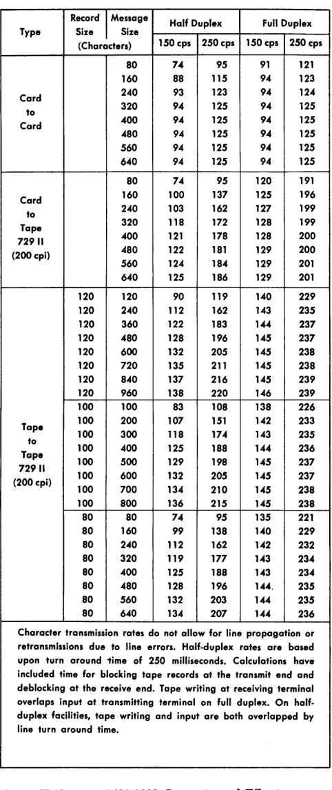
The chart (Figure H-ll) shows a comparison of effec-tive transmission rates of characters per second for the
IBM 1401-1460/1009 Data Transmission Unit.
Record
I
Message Half Duplex Full Duplex Type Size Size(Characters) 150 cps 250 cps 150 cps 250 cps SO 74 95 91 121 160 S'S 115 94 123 Card 240 93 123 94 124 to 320 94 125 94 125 Card 400 94 125 94 125 480 94 125 94 125 560 94 125 94 125 640 94 125 94 125 80 74 95 120 191 Card 160 100 137 125 196 to 240 103 162 127 199 Tape 320 118 172 128 199 72911 400 121 178 128 200 (200cpi) 480 122 181 129 200 560 124 184 129 201 640 125 186 129 201 120 120 90 119 140 229 120 240 112 162 143 235 120 360 122 183 144 237 120 480 128 196 145 237 120 600 132 205 145 238 120 720 135 211 145 238 120 840 137 216 145 239 120 960 138 220 146 239 100 100 83 108 138 226 Tape 100 200 107 151 142 233 100 300 118 174 143 235 to
100 400 125 18S 144 236 Tape
100 500 129 198 145 237 72911
100 600 132 205 145 237 (200 cpi)
100 700 134 210 145 238 100 800 136 215 145 238 80 80 74 95 135 221 80 160 99 138 140 229 80 240 112 162 142 232 80 320 119 177 143 234 80 400 125 188 143 234 80 480 128 196 144, 235 80 560 132 203 144 235 80 640 134 207 144 236 Character transmission rates do not allow for line propagation or retransmissions due to line errors. Half-duplex rates are based upon turn around 1ime of 250 milliseconds. Calculations have included time for blocking tape records at the transmit end and deblocking at the receive end. Tape writing at receiving terminal overlaps input at transmitting terminal on full duplex. On half-duplex facilities, tape writing and input are both overlapped by
line turn around time.
Figure H-U. IBM 1401-1009 Comparison of Effective
[image:10.612.310.551.58.631.2]IBM 1404 Printer
The IBM 1404 Printer, Model 2 (Figure H -12), is
an-other output medium for the IBM 1401 Data
Process-ing System, and it can be used on all 1401 systems except A and D. It is a combination printer, capable of processing either cut-card forms or continuous forms. The 1404 retains all the basic features of the
IBM 1403 Printer -- tape-controlled caniage, printing
unit and continuous forms caniage and incorporates the card feeding mechanism--under the control of the 1401 stored program and the tape-controlled caniage.
Data Flow
A printing operation requires moving and ananging of data into the core-storage print area (locations 201 through a32) before a printing operation is executed. When a WRITE LINE instruction is given, the data to
be printed is read out of core storage to the B-register character by character. As each character is read into the B-register from a particular core-storage position, it is compared in the print-compare area to the charac-ters on the chain in the corresponding print position. When the comparison is equal, the hammer is fired, printing that character.
The IBM 1404 Printer operates at a maximum rate of
600 lines per minute when printing on continuous forms or it can print on card documents at a rate of 800 cards per minute.
The print-cycle timing is 100 ms, which permits 16 ms of processing time, and the 1401 is interlocked for
Figure H-12. IBM 1404 Printer, Model 2
84 ms print-interlock time. If additional form-move-ment time is required, this time must be added to the basic 100-ms cycle to determine the printing speed.
IBM 1404 Instructions
The following instructions control IBM 1404 Printer
operations. The instructions that relate to reading cards from the 1404 use the d-character, 0 (zero), thus modifying certain existing 1401 instructions. Other in-structions in the following set apply without modi-fication.
Read Card from 1404 Printer
Instruction Format.
Mnemonic
R
Op Code
1
d-character
o
Function. This instruction causes a card to be read, and as many as 30 columns of information to be transferred into core-storage positions 334 to 363. The d-character specifies that this is a read instruc-tion for the 1404. There is no valid READ AND BRANCH
instruction for the 1404.
Word Marks. Word marks are undisturbed.
Timing. T
=
.0115 (LI+
1)+
I/O ms.A 1404 card read cycle (1/.0 time) requires a total of 150 ms. The cycle is divided into three major operations. (See section on Timing.)
Note 1. When the 1404 is being used as the only card input medium, a storage-scan operation should be performed or the 1404 card read-in area should be given a clear operation prior to the first 1404 card read.
Note 2. The read instruction must always follow the instruc-tion
£
1 or the instructions F A. and 2.Address Registers After Operation.
I-Add. Reg. A-Add. Reg.
NSI Ap
B-Add. Reg.
364
Example. Read as many as 30 columns (specified by the 1404 control panel), and transfer the data to IBM
1401 core-storage positions 334-363 (Figure H-13).
Assembled Instruction: ! 0 Figure H-13. Read Card from 1404 Printer
[image:11.612.72.311.482.704.2]Write Line
Instruction Format.
Mnemonc
W
Op Code
2
Function. This instruction causes the data in the print area to be transferred to the printer. The program continues after printing is complete. The printer takes an automatic space after printing a line, except when a SPACE AFTER PRINT or a SKIP AFTER PRINT
control-carriage instruction is used. Word Atlarks. Word marks are not affected.
Timing. T
=
.0115 (LI+
1)+
I/O ms. Address Registers After Operation.I-Add. Reg. A-Add. Reg.
NSI Ap
B-Add. Reg.
332
Example. Print the data in the print area (Figure H-14).
Assembled Instruction: 1 Figure H-14. Write Line
Write and Read on 1404 Printer
Instruction Format.
Mnemonic
WR
Op Code
3
d-character o
Function. This instruction combines the functions of
READ CARD FROM 1404 PRINTER (1 0) and WRITE LINE (g). The print operation takes priority, and the print cycle is completed before the card reading operation takes place.
Without the special feature, print storage, this in-struction must follow an .E A inin-struction. In this instance, no processing time is available between print and read.
With the print-storage feature, this instruction can follow either an F 1 or an .f A instruction. If it follows
E
1, it must be given no more than 29.2 ms later.Word Mm'ks, Word marks are undisturbed.
Timing. T
=
.0115 (LI+
1)+
I/O ms. Address Registers After Operation.I-Add. Reg. A-Add. Reg.
NSI Ap
B-Add. Reg.
081
Example. Write a line, and read as many as 30 col-umns (specified by the 1404 control panel) and transfer the data to IBM 1401 core-storage positions 334-363 (Figure H -15) .
Assembled Instruction: ~ 0 Figure H-15. Write and Read on 1404
Control Carriage
Instruction Format.
Mnemonic
CC Op Code F
d-character
x
Function. This instruction causes the carriage to move as specified by the d-character. The instructions.E 1 and F A cause normal carriage skips to channelL If the 1404 card feed switch is ON:
1. .f 1 causes the immediate eject to the stacker of the card at the print station, a new card to be posi-tioned at the first printing line (channell) in the print station, and a new card to be fed from the hopper.
2 .
..E
A causes the card at the print station to eject immediately after the next print cycle, a new card to be positioned at the first printing line (channell) in the print station and a new card to be fed from the hopper.All other.f (d) instructions cause normal carriage control operations.
Word Marks. Word marks are not affected.
Address ]legisters After Operation.
I-Add. Reg.
NSI
A-Add. Reg.
dpp
B-Add. Reg.
dpp
Example. Eject the card at the print station after the next print cycle (Figure 1I-16).
Assembled Instruction: ! A
Figure H-16. Control Carriage
Branch if ~ndicator On
I nstrucUon Format.
Mnemonic
B
Op Code
B
I-address
xxx
d-character
o
Function. As in any 1401 BRANCH IF INDICATOR ON
in-struction, the d-character specifies the indicator tested. If the special feature, read-compare, is in-stalled, the d-character, 0 (zero), permits testing for a validity error after a 1404 card reading operation. If it is used, this instruction must be given after a
!
0 or ~ 0 instruction, and before the next!' 1 or !' A instruction.Word Marks. Word marks are not affected.
Timing. T
=
.0115 (LI+
1) ms.Address Registers i\fter Operation.
Branch No Branch
Branch No Branch
With Indexing
I-Add. Reg.
BI NSI
A-Add. Reg.
BI BI Without Indexing BI NSI BI BI
B-Add. Reg.
NSI dbi
Cleared dbi
Example. Test to see if there was an invalid card code read by the read-compare brushes during the last read operation in the 1404. If there was an error, branch to location 0787 (Figure H -17) .
Assembled Instruction: .§ 787 0
Figure H-17. Branch if Invalid Card Code Indicator On
Compare
Instruction Format.
Mnemonic
C
Op Code
C
A-address
xxx
B-addres$
363
Function. The data in the A-field is compared to an equal number of characters in the B-field. The bit configuration of each character in the two fields is compared. If there is an unequal comparison, an indicator turns on. This indicator can. then be tested by a BRANCH IF INDICATOR ON instruction.
If the read-compare feature is installed in the IDM
1404 Printer, any of the 30 (334-363) core-storage locations, assigned as a read-in area from the 1404, can be compared with any other field.
Word Marks. The first word mark encountered stops the operation. If the A-field is longer than the B-field, the extra positions in the A-field are not com-pared. If the B-field is longer than the A-field, an unequal compare results.
Timing. T
=
.0115 (LI+
1+
LA+
LB )ms.Note. Both fields must have exactly the same bit configuration to be equal.
Address Registers After Operation.
I-Add. Reg. A-Add. Reg. B-Add. Reg.
NSI A-Lw B-Lw
Example. Compare the 10-digit serial number of one card with that of the preceding card (moved to loca-tions 681-690). Then test the unequal-compare indi-cator. If the serial numbers are equal, continue the program in sequence. If they are unequal, branch to location 0927 for the next instruction (Figure H-18).
LINE COUNT
.
I I'"
0 I 0 0 • 0
(AIOPERAIIO IBIOPERAND LABEL OPERATION
ADDRESS 1~1 CHAR. ·1 = ADDRESS I~I
1314 '1'7 ADJ. un
Ir.. 10.':.9.0 I I
I IO.3.~.~ I
, L-L I
I" I 1".0 .... 11 I I 1 L-L
Assembled Instruction: ~ 690 343 !927 I
I
:
I
Figure H-18. Compare
CHAR. 1:1 d
ADJ. "31
1 1 1/
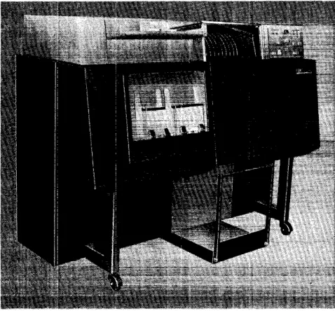
IBM 1407 Console Inquiry Station
The IBM 1407 Console Inquiry Station (Figure H-19)
provides a manually controlled means of communica-tion between the operator and the IBM 1401 Data
Proc-essing System.
Data Flow
The 1407 can control both reading from, and writing into, storage by using an instruction format keyed into the system to direct the particular operation desired. This permits the operator to examine or alter the status of data or instructions stored in the system. A request can be made to the system for the specific data to be typed out for verification. This also serves as a record of the changes made to the storage information.
IBM 1407 Instructions
Read from Console Printer
Instruction Format.
Mnemonic Op Code A-address B-address d-character
MV M %TO xxx R
Function. This instruction causes the enter key-light to come ON, the keyboard to unlock, and the data (to
be typed on the 1407) to enter 1401 core storage. The A-address specifies an inquiry station operation. The B-address is the high-order position in 1401 core storage wherein the data is to be stored. The d-character specifies a read-in operation. The inquiry request indicator must be ON to process this
instruc-tion.
Figure H-19. IBM 1407 Console Inquiry Station
H-IO
Word Marks. A group-mark with a word-mark must be inserted in 1401 core storage to the right of the last character sent to the 1401 from the 1407. An-other method of terminating a read-in operation is pressing the clear key.
Timing. T
=
.0115 (LI+
1) ms+
typing time.Note. The lower case b (special character) or space bar causes a space to be taken and a blank to enter core storage. If the b-key is pressed, a lower case b is printed. The method of entering data is discussed in the manual on 1407 Console Inquiry Station, Form A24-30B4.
Address Registers After Operation.
I-Add. Reg. A-Add. Reg. B-Add. Reg.
NSI %30 B+LB
Example. Transfer the data typed on the IBM 1407 to
the area in 1401 core storage labeled INQIN (0785), Figure H-20.
Autocoder
L
Label .~tl~r . :
'1Mt[:b}~r
N9'
Ji:
R
~'
OPERAND ~'. ,,~
Assembled Instruction: M %TO 785 R Figure H-20. Read from Console Printer
Read from Console Printer with Word Marks
Instruction Format.
Mnemonic Op Code A-address B-address d-character
LV L %TO xxx R
Function. This instruction causes the enter key light to come ON, the keyboard to unlock, and the data
with word mark (to be typed on the 1407) to enter 1401 core storage. The A-address specifies an inquiry station operation. The B-address is the high-order position, in 1401 core storage, in which the data is to be stored. The d-character specifies a read-in op-eration. Word marks are entered by first pressing the word-mark key, and then pressing the associated character key. Characters with a word mark print in red. The inquiry request indicator must be ON to
Word Marks. A group-mark with a word-mark must be inserted in 1401 core storage to the right of the last character sent to the 1401 from the 1407. Another method of terminating a storage read-in operation is to press the clear key.
Timing. T
=
.0115 (LI+
1) ms+
typing time.Note. The lower case b (special character) or space bar causes a space to be taken and a blank to enter core storage. If the b-key is pressed, a lower case b is printed. The method of entering data is discussed in the manual on 1407 Console Inquiry Station, Form A24-30B4.
Address Uegisters After Operation. I-Add. Reg. A-Add. Reg.
NSI %30
B-Add. Reg.
GMWM+1
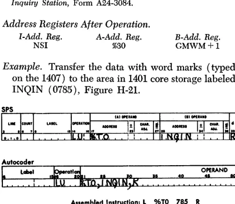
Example. Transfer the data with word marks (typed on the .1407) to the area in 1401 core storage labeled INQIN (0785), Figure H-21.
Autocoder
~
it~,TNGIfQ:, ~
OPERAND10 4' IQ
Assembled Instruction:.!:. %TO 785 R Figure H-2!. Read from Console Printer with Word Marks
Write on Console Printer
Instruction Format.
Mnemonic Op Code A-address B-address d-character
MU M %TO xxx W
Function. This instruction causes data from 1401 stor-age to be typed by the inquiry station. While the data is being typed, the typeout light is ON. The
B-address is the high-order position in 1401 core stor-age of the data to be transferred to the console printer, The d-character specifies a write operation. Word Marks. A group-mark with a word-mark in 1401 core storage stops the transfer of data to the 1407 and causes a carriage return. Pressing the clear key also stops the transfer of data from the 1401.
Timing. T
=
.0115 (LI+
1) ms+
typing time.Note. Characters that have incorrect parity ( even-bit) are typed as a >1< if the process-check stop switch is OFF. If the switch is ON, typing stops before typing the incorrect char-acter.
Address Registers After Operation. I-Add. Reg. A-Add. Reg.
NSI %30
B-Add. Reg.
GMWM+1
Example. Type the data, beginning in the area labeled INQOUT (0785) and ending with a group-mark, with a word-mark (Figure H-22).
Assembled Instruction: M. % TO 785 W Figure H-22. Write On Console Printer
Write on Console Printer with Word Marks
Instruction Format.
Mnemonic Op Code A-address B-address d-character
LU L %TO xxx W
Function. This instruction causes data from 1401 stor-age to be typed by the inquiry station. While the data is being typed, the typeout light is ON. The
A-address specifies an inquiry station operation. The B-address is the high-order position in 1401 core storage of the data to be transferred to the type-writer. The d-character specifies a write operation.
Word Marks. A group-mark with a word-mark stops the transfer of data to the 1407 and causes a car-,riage return. Pressing the clear key also stops the
transfer of data from the 1401.
Timing. T
=
.0115 (LI+
1) ms+
typing time. Note. Characters that have a word mark in association withthem are typed in red. All other characters are typed in black. A space is printed as a lower case h. Characters with incor-rect parity (even-bit) are typed as a >t< if the process-check stop switch is OFF. If the switch is ON, typing stops before typing the incorrect character.
[image:15.612.69.311.195.405.2]Address Registers After Operation.
I-Add. Reg. A-Add. Reg.
NSI %30
B-Add. Reg.
GMWM+l
Example. Type the data with word marks located in the area labeled INQOUT (0785) and ending with a group-mark with a word-mark (Figure H-23).
Autocoder
~
Labe. OPERAND~'. ~
. :
Assembled Instruction:.!:. %TO 785 W Figure H-23. Write On Console Printer with Word Marks
Line Space
Instruction Format.
Mnemonic Op Code A-address B-address d-character
LU or MU
..h
or M %TO xxx WFunction. This instruction causes the console printer to space one line. The B-address is the storage loca-tion of a group-mark with a word-mark.
Word Marks. A group-mark with a word-mark must be at the B-address.
Timing. T
=
.0115 (Lr+
1) ms+
space time.Note. Multiple line spacing is controlled by this instruction and
by the setting of the line-space lever.
Address Registers After Operation.
I-Add. Reg. A-Add. Reg. B-Add. Reg.
NSI %30 B+l
Example. Space a single line on the console printer. The storage position labeled GMWM (0895)) con-tains a group-mark with a word-mark (Figure H-24)~
Autocoder
~
Labe. OPERAND•
~~
I I-,-.~:~
. . . - - , - - , : ' ... 10 Assembled Instruction:",,!:, %TO 895 WFigure H-24. Line Space
H-12
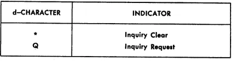
d-CHARACTER INDICATOR
* Inquiry Clear
Q Inquiry Request
Figure H-25. IBM 1407 Branch Instruction d-Character
Branch if Indicator On
Instruction Format.
Mnemonic
SPS B
A BIN
Op Code
B
I-address
xxx
d-character
x
Function. The d-character specifies the indicator tested. If the indicator is ON, the next instruction is
taken from the I-address. If the indicator is OFF, the
next sequential instruction is taken. Figure H-25 shows symbols that are valid d-characters and the indicators they test.
Indicators. Inquiry Clear - This indicator turns ON
when the clear key-light is pressed, if the 1401 is in the RUN mode. It turns OFF when the 1401 program
processes a console inquiry instruction or the start reset key on the 1401 console is pressed. It must be tested before processing the next inquiry.
Inquiry Request - This indicator turns ON when
the request enter key-light is pressed to signal the 1401 that an inquiry is to be processed, and the 1401 is in the RUN mode. It is turned OFF after the 1401
processes a console inquiry instruction. Pressing the start reset key on the 1401 console or the clear key on the 1407 also turns this indicator off.
Word Marks. Word marks are not affected.
Timing.
Without IndeXing: T = .0115 (Lr
+
1) ms. With Indexing:T
=
.0115 (Lr+
2) ms.Address Registers After Operation.
I-Add. Reg. A-Add. Reg.
NSI BI
B-Add. Reg.
dbb
Example. Branch to the inquiry routine labeled INQ-RUT (0950) if the inquiry request indicator is ON
[image:16.612.53.530.38.749.2] [image:16.612.310.548.60.122.2]OPERAND
:'.
.
~
Assembled Instrucfrion:! 950 Q
Figure H-26. Branch if Inquiry Request Indicator On
IBM 14'18 Optical Character Reader
Numeric data on printed card or paper documents can be read optically into 1401 or 1460 core storage with the IBM 1418 Optical Character Reader, Modell, with
three stackers, can select the documents according to class, or general category; Model 2 (Figure H-27), with 13 stackers, in addition to sorting by class, can sort each document numerically. Model 3, which is similar in appearance and operation to the Modell, has a broader range of document-handling capabilities. The Model 3 is particularly adaptable to cash-account-ing applications where a small shIb is customarily returned with a payment.
Figure H-2'7. IBM 1418 Optical Character Reader, Model 2
IBM 1418 Instructions
Eleven instructions are available for on-line control of the IBM 1418. The €Jperation codes for programming
the 1418 are:
Control Unit
Instruction Format.
Mnemonic
CU
Op Code
U
A-address
%S2
d-character
d
Function. This instruction controls 1418 document feeding according to the d -character.
Operation d-C haracter
E ENGAGE: Selects the 1418 and instructs it to start feeding documents continuously. Feed-ing continues until a DISENGAGE instruction is executed, or until either a system or a 1418 stop automatically disengages the 1418.
D DISENGAGE: Instructs the 1418 to stop feed-ing documents. Documents already beyond the ready station are read and processed after the 1418 is disengaged.
Word Marks. Word marks are rrot affected.
Timing. T= N (LI
+
1) ms+
I/O N=
.0115 (1401); .006 (1460)Example. Engage the 1418 and start feeding docu-ments (Figure H-28).
Autocoder
I. ,
LabelOPERAND
10 00
I I 4Q
10 ! :
Assembled Instruction: ~ %52 E
Figure H-28. Control Unit (Engage)
Read in Move Mode
Instruction Format.
Mnemonic Op Code A-address B-address. d-character
MU M %S2 xxx R
Function. This instruction moves the character read by the 1418 from the character register to the
storage position specified by the B-address. A read instruction must be given for each character trans-ferred to the 1401 or 1460.
Word Marks. Word marks are not affected.
Timing. T = N (LI
+
1) ms+
message length+
docu-ment movement~+
1..:!Refer to Figure H-41.
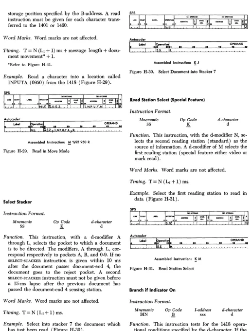
Example. Read a character into a location called INPUTA (0950) from the 1418 (Figure H-29).
Autocoder
~
Label.
:
Assembled Instruction: M %52950 R Figure H-29. Read in Move Mode
Select Stacker
Instruction Format.
Mnemonic
SS
Op Code
K
d-character
d
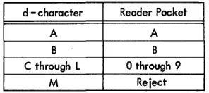
Function. This instruction, with a d-modifier A
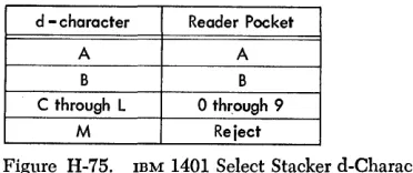
through L, selects the pocket to which a document is to be directed. The modifiers, A through L, cor-respond respectively to pockets A, B, and 0-9. If no
SELECT-STACKER instruction is given within 10 ms
after the document passes document-end 4, the document goes to the reject pocket. A second
SELECT-STACKER instruction must not be given before
a 15-ms lapse after the previous document has passed the document-end 4 sensing station.
Word Marks. Word marks are not affected.
Timing. T
=
N (LI+
1) ms.Example. Select into stacker 7 the document which has just been read (Figure H -30) .
Autocoder
Label
.
:
Assembled Instruction: K J Figure H-30. Select Document into Stacker 7
Read Station Select (Special Feature)
Instruction Format.
Mnemonic
SS
Op Code
K
OPERAND
:',
.
~
d-character
d
Function. This instruction, with the d-modifier N, se-lects the second reading station (standard) as the source of information. A d-modifier of M selects the first reading station (special feature either video or mark read).
Word Marks. Word marks are not affected.
Timing. T
=
N (LI+
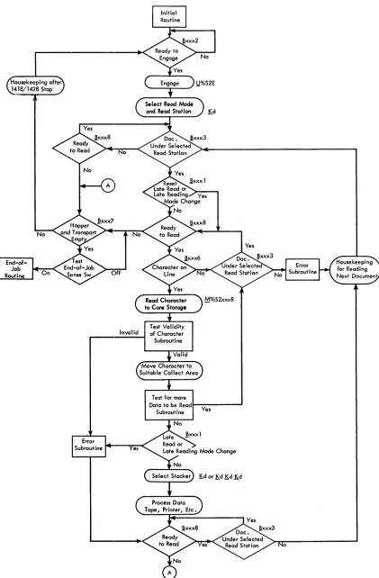
1) ms.Example. Select the first reading station to read in data (Figure H-31).
Autocoder
Label
.
:
I t IAssembled Instruction: K M Figure H-31. Read Station Select
Branch if Indicator On
Instruction Format.
Mnemonic
BIN
Op Code
B
I-address
xxx
OPERAND
: ' , !
~
d-character
d
[image:18.617.47.566.39.719.2]indicator is ON, the next instruction is taken from the
I-address; if OFF, the 1401 or 1460 goes to the next
sequential instruction.
d-Character Branch and Function
1 BRANCH ON LATE READ
Branch if the late-read indicator is ON. The test for branch-1 resets this indicator.
The 1418 is scanning as long as a docu-ment is under the selected read station. Un-less all information scanned is transferred to the system, the late-read indicator turns ON.
The stored program must include turning
OFF this indicator prior to reading a
signifi-cant field on a document. Testing this indi-cator at the end of a significant field deter-mines whether or not all the information was transferred to core storage.
2 BRANCH ON READY TO ENGAGE
Branch if the 1418 is ready to engage. This indicator remains ON when the 1418 is: a. disengaged with a document at the ready station,
b. ready to operate (all interlocks normal, drive motors up to speed), and
c. not in register-run, test, or off-line mode. Branching on ready-to-engage must pre-cede each ENGAGE instruction. Not
branch-ing to an ENGAGE instruction allows the
stored program to continue processing when the 1418 operating conditions are not satis-fied.
Single-document feeding is accomplished by consecutive ENGAGE-DISENGAGE instruc-tions following a branch on the ready-to-engage test.
3 BRANCH ON DOCUMENT UNDER SELECTED READ STATION
The leading edge of the document at the selected reading station turns ON this indica-tor provided that the document has not caused a hopper check. The trailing edge turns it OFF. A prior STATION-SELECT
instruc-tion (~M or !)N) specifies the particular read-ing station.
Many 1401 or 1460/1418 subroutines re-quire a document either under or not under
a selected read station during their execu-tion. Branch 3 is used to delay the program by a loop until the document is in proper position. Meeting the branch-3 conditions allows the stored program to enter these sub-routines. For example, branching on branch 3 precedes the character-on-line test. This assures that a document is present while the program is looking for a character to be read at the selected read station.
If a document is to be read only partially, a program delay may be necessary to pre-vent reading the trailing edge of that docu-ment. A branch 3 can be programmed to loop until that particular document has left the reading station.
The ready-to-read (branch 8) test should precede testing each branch-3 instruction. This allows the system to continue process-ing if the 1418 is no longer ready to read.
5 BHANCH ON DOCUMENT END
Branch if the trailing edge of the document has passed the point specified by the docu-ment-end switch. The leading edge of the next document resets the indicator. This test is used to delay the stored program until a document has passed the specified point.
The ready-to-read (branch 8) test should precede testing each branch-5 instruction. This allows the system to continue process-ing if the 1418 is no longer ready to read.
6 BRANCH ON CHARACTER ON LINE
Branch if a character is available to the
sys-tem. This indicator is ON whenever the 1418
places a character in the on-line register. A character must be in the on-line register be-fore a read instruction ( M %S2 xxx R) is given. A character is neve;- placed in the on-line register from a scanned document that caused a hopper check.
The ready-to-read (branch 8) test should precede testing each branch-6 instruction. This allows the system to continue process-ing if the 1418 is no longer ready to read.
7 BRANCH ON EMPTY HOPPER AND TRANSPORT (END OF FILE)
This indicator turns ON when the hopper
be-comes empty and the trailing edge of the last document passes a point one-half inch (10 ms) beyond the document-end 4 sens-ing station.
This instruction should be given only fol-lowing a ready-to-read (branch 8) failure-to-branch to indicate the 1418 is out of docu-ments. Failure of the branch-7 to branch at this time indicates a condition requiring operator intervention, for example: jam, full pocket, open interlock, etc. The branch-7 indicator, in conjunction with a sense switch on the system console, can signal an end-of-job condition, and release the stored program from 1418 input:.
8 BHANCH ON READY TO READ
Branch if the 1418 is ready to read. This indicator turns ON as the first document leaves the ready station. The indicator re-mains ON until the last document passes a
point one-half inch (10 ms) beyond the document-end 4 sensing station, or until the 1418 stops for an empty hopper, a feed jam, or a full pocket.
The branch-8 instruction is used in con-junction with other instructions to indicate that the 1418 is ready to read documents.
Word Marks. Word marks are not affected.
Timing.
No Branch:
T
=
N (LI+
1) ms. Branch (without indexing):T
=
N (LI+
1) ms. Branch (with indexing):T=N (L1+2) ms.
Example. If a late read condition occurs, branch to a routine called LA TRD (0841) (Figure H-32).
Autocoder
OPERAND
40
:~ ,,~
Assembled Instruction: B 841 1
Figure H-32. Branch if Late Read Condition Indicator On
IBM 1428 Alphameric Optical Reader
The ffiM 1428 (Figure H-33) can be conneoted, through a serial input/output adapter, to an IBM 1401 or 1460
system. When connected to a 1401 or 1460, the 1428 supplies high-speed alphameric input to the data proc-essing system from printed documents of various sizes. Thus the 1428 provides for direct entry into the 1401 or 1460 system of data from such documents as in-surance premium notices, charge sales invoices, opera-tions and route slips, payroll and dividend checks, and mail orders.
The ffiM 1428, Modell, is equipped with three sorter pockets. The Model 2 is equipped with thirteen pockets. The Model 3, which is similar to the Modell in appearance and operation, can handle documents of a broader size range. It is particularly adaptable to handling small stub-size documents such as those re-turned with a payment in many cash-accounting appli-cations. The ffiM 1428, Model 2, can also be used off-line as an optical sorter.
IBM 1428 Instructions
Twelve instructions are available for on-line control of the ffiM 1428. The 1401 or 1460 operation codes for programming the 1428 are:
Control Unit
Instruction Format. Mnemonic
CU Op Code U
A-address
%S2
d-character
d
Function. This instruction controls ffiM 1428 document feeding according to the d-character.
Ii-16
Figure H-33. mM 1428 Alphameric Optical Reader, Model 2
d-Character E
D
Operation
ENGAGE: Selects the 1428 and instructs it to
start feeding documents continuously. Feed-ing continues until a disengage instruction is executed, or until a 1401/1460 with 1428 stop automatically disengages the 1428.
DISENGAGE: Instructs the 1428 to stop
feed-ing documents. Documents already beyond the ready station are read and processed.
Word Marks. Word marks are not affected.
Timing. T
=
N (Lr+
1) ms+
I/O.Example. Engages the 1428 and starts feeding of documents (Figure H-34).
Autocoder
~
label.
:
Assembled Instruction: ~ %52 E Figure H-34. Control Unit (Engage)
Reading Mode Determination
Instruction Format. Mnemonic
SS
Op Code
K
d-character
d
included in the corresponding alphabetic, numeric, or alphameric character set.
C - A through Z
I -
$ / ~ , . defines the alphabetic set. E - 0-9I -
$ / I) , • defines the numeric set.F - All characters recognized by the 1428 define the alpha-meric set.
Pressing the 1428 reset key in an on-line operation automatically places the system in the alphameric reading mode.
A programmed reading-mode change must be given within .8 ms after a character has been placed in the 1428 on-line character register. Failure to con-sider this timing results in missing the next character following the programmed reading-mode change. Word Marks. Word marks are not affected.
Timing. T
=
N (LI+
1) ms.Example. Read only the numeric set defined by the d-character E (Figure H-35).
Autocoder
~
!trotl~ ~'.
!~o
1540
OPERAND 15 00
Assembled Instruction: K E Figure H-35. Reading Mode Determination
Read in Move Mode
Instruction Format.
Mnemonic Op Code A-address B-address d-character
MU M %S2 xxx R
Function. This instruction moves the character read by the 1428 from the character register to the core storage specified by the B"address. A read instruc-tion must be given for each character transferred to the 1401 or 1460.
Word Marks. Word marks are not affeoted.
Timing. T
=
N (Lr+
1) ms+
message length+
docu-ment movement~+
1.Il<Refer to Figure H-41.
Example. Read a character into location called INPUTA (0880) from the 1428 (Figure H-36).
Autocoder
~
LobelAssembled Instruction: M %52 880 R Figure H-36. Read in Move Mode
Select Stacker
Instruction Format.
Mnemonic
SS
Op Code
K
d-character
d
Function. The stacker selection is accomplished in the 1428 by either one instruction with a d-modifier or the combination of three consecutive instructions with their appropriate d-modifiers. A SELECT STACKER
ins,truction must be given within 10 ms after the document passes document-end 4.
A SELECT STACKER instruction must be issued by
the program for some pocket, including the reject pocket, for every document that was scanned and had any of its characters read into core storage. If a
SELECT STACKER instruction is not issued, a sort check
occurs and the system stops.
Failure to give a SELECT STACKER instruction for a
document that is scanned, but that has none of its characters read to the process unit from the on-line register, results in the document being rejected with-out a selection error and withwith-out stopping the sys-tem. The SELECT STACKER instructions with their
d-modifiers are as follows: 1401/1460 Instruction
Configuration 1428 Pocket Selected o
1
2
3 4
5
6 7 8 9
A
B
R
Word Marks. Word marks are not affected.
Timing. T
=
N (LI+
1) ms.Example. Select into stacker pocket 1 the document that was scanned and had its characters read to core storage (Figure H -37) .
Autocoder
~
La'.
:
Assembled Instruction: K A Figure H-37. Select Document into Stacker 1
Read Station Select (Special Feature)
Instruction Format.
Mnemonic
SS
Op Code
K
OPERAND
:'.
,,~
d-character
d
Function. This instruction, with the d-modifier N, se-lects the second reading station (standard) as the source of information. A d-modifier of M selects the first reading station (special feature: either video or mark read).
Word Marks. Word marks are not affected.
Timing. T
=
N (LI+
1) ms.Example. Select the first reading station to read in data (Figure H-38).
Autocoder
~
La' OPERAND:~ ,,~
.
:
Assembled Instruction: K M Figure H-38. Read Station Select
Branch if Indicator On
Instruction Format.
Mnemonic
B
Op Code
B
I-address
xxx
d-character
d
Function. This instruction tests for the 1428 opera-tional conditions specified by the d-character. If the indicator is ON, the next instruction is taken from the
I-address. If the indicator is OFF, the stored program
goes to the next sequential instruction. d-Character
1
2
3
Branch and Function
BRANCH ON LATE READ OR LATE READING MODE CHANGE
Branch, if the late-read or late-reading mode change indicator is ON. The test for branch 1
resets this indicator.
The 1428 scans as long as a document is under the selected read station. Unless all information scanned is transferred to the system, the late-read indicator turns ON. The stored program must include turning OFF
this indicator prior to reading a significant field on a document. Testing this indicator at the end of a significant field determines whether or not all the information was trans-ferred to core storage.
Failure to change reading modes within the specified .8 ms after the branch-6 indi-cator turns ON also turns this indicator ON.
BRANCH ON READY TO ENGAGE
Branch if the 1428 is ready to engage. This indicator remains ON when the 1428 is: a. disengaged with a document at the ready station,
b. ready to operate (all interlocks normal, drive motors up to speed), and
c. not in register-run, test, or off-line mode. Branching on READY TO ENGAGE must pre-cede each engage instruction. Not branching to an engage instruction allows the program to continue processing when the 1428 oper-ating conditions are not satisfied.
Single-document feeding is accomplished by consecutive engage-disengage instructions following a branch on the ready-to-engage test.
BRANCH ON DOCUMENT UNDER SELECTED READ STATION
The leading edge of the document at the selected reading station turns ON this indi-cator, provided that the document has not caused a hopper check to occur. The trailing edge turns it OFF. A prior station-select in-struction (~M or ,KN) specifies the particular reading station.
5
6
7
subroutines. For example, branching on branch-3 precedes the character-on-line test. This assures that: a document is present while the program is looking for a character to be read at the selected read station.
If a document: is to be read only partially, a program delay may be necessary to pre-vent reading the trailing end of that docu-ment. A branch 3 can be programmed to loop until that particular document has left the reading station.
The ready-to-read (branch-8) test should precede testing each branch-3 instruction. This allows the 1401 or 1460 to continue processing if the 1428 is no longer ready to read.
BRANCH ON DOCUMENT END
Branch, if the trailing edge of the document has passed the point specified by the docu-ment-end switch. The leading edge of the next document resets the indicator. This test is used to delay the stored program until a document has passed the specified point.
The ready-to-·read (branch-8) test should precede testing each branch-5 instruction. This allows the 1401 or 1460 to continue processing if the 1428 is no longer ready to read.
BRANCH ON CHARACTER ON LINE
Branch, if a character is available to the 1401 or 1460. This indicator is ON whenever the 1428 places a character in the on-line register. A character must be in the on-line register before a read instruction (M %82
xxx R) is given.
-A character is never placed in the on-line register from a scanned document that caused a hopper-check to occur.
The ready-to·-read (branch-8) test should precede testing each branch-6 instruction. This allows the 1401 or 1460 to continue processing if the 1428 is no longer ready to read.
BRANCH ON EMPTY HOPPER AND TRANSPORT (END OF FILE)
This indicator turns ON when the hopper
becomes empty and the trailing edge of the last: document passes a point one-half inch (10 ms) beyond the document-end 4 sensing station.
This instruction should be given only fol-lowing a ready-to-read ( branch-8) failure, to branch to indicate the 1428 js out of documents.
The branch-7 indicator, in conjunction with a sense switch on the console, can signal the end-oF-job condition and release the program from 1428 input.
8 BRANCH ON READY TO READ
Branch, if the 1428 is ready to read. This indicator turns ON as the first document
leaves the ready station. The indicator re-mains ON until the last document passes a
point one-half inch (10 ms) beyond the document-end 4 sensing station, or until the 1428 stops for an empty hopper, a feed jam, or a full pocket.
The branch-8 instruction is used in con-junction with other instructions to indicate that the 1428 is ready to read documents.
Word Marks. Word marks are not affected.
Timing. No Branch:
T
=
N (LI+
1) ms. Branch (without indexing)T
=
N (LI+
1) ms.Branch (with indexing)
T
=
N (LI+
2) ms.Example. If a late read condition occurs, branch to a routine called LATRD (0841) (Figure H-39).
Autocoder
Label tratl~
I I I I 0
: I
OPERAND
~o
.
:
Assembled Instruction: B 841 1
Figure H-39. Branch if Late Read Condition Indicator On
IBM 1401 or 1460 with 1418 or 1428
General Block Diagram
The general block diagram (Figure H-40) illustrates the 1401 or 1460 with 1418 or 1428 operation codes used in a sample program. Other programs can be equally valid. However, several machine functions make using some of the routines shown advisable. Except for a few variations, the block diagram and program description for both the 1418 and 1428 are identical. The variations are discussed individually for each machine.
1. The main loop for the IBM 1418 or 1428 begins at a
ready-to-engage test. When this test has been con-ditioned to branch to ENGAGE, the optical reader
starts feeding documents.
2. (1418) Select the reading station that is to be the source of information. Unless multiple-line docu-ments are to be read, the station selected for a par-ticular run remains selected until power is turned
OFF to the system.
2. (1428) Select the reading status of the system to read the character-set to be scanned. The reading status of the machine can be changed at any time during a document cycle, provided that the pviously mentioned timing considerations are re-spected. Failure to comply may result in setting the late-read or late-reading mode change indi-cator and in missing the nrst character following a programmed reading mode change. Select the reading station that is to be the source of informa-tion. Unless multiple-line documents are to be read, the station selected for a particular run re-mains selected until power is turned OFF to the
system.
3. Test for DOCUMENT UNDER SELECTED READ STATION.
The program goes into a subroutine with a READY TO READ while waiting for the leading edge of the
document to reach the selected reading station. 4. Reset late-read indicator (branch 1). Testing this
indicator resets the indicator if it is ON. The
indi-cator can then be tested (item 8) at the end