2017 International Conference on Information, Computer and Education Engineering (ICICEE 2017) ISBN: 978-1-60595-503-2
Design of Control System of Low Speed
Brushless DC Motor
De-Sheng Zhong
ABSTRACT
The paper introduced the design of the low speed Brushless DC Motor control system. Paper also design the procedure total diagram of the software which control the Brushless DC Motor. The experiment shows that the design of the motor, the speed response of the no-load start is fast, the overshoot is small, the speed fluctuation is small, has the good dynamic static characteristic, has certain application value.
KEY WORDS: low speed; Brushless DC Motor; control system
Introduction
At present, the screw pump pumping unit is widely used in oil field production. It requires the drive motor to provide high torque, slow speed and smooth operation.Using the asynchronous motor, the screw pump is driven by decelerating mechanism, which is inefficient, noisy and large. Brushless dc motor has the advantages of high efficiency, high torque and smooth running. It is suitable for driving motor with screw pump type pumping.Furthermore, the low speed brushless dc motor can realize the direct drive of the pumping unit, which simplifies the transmission mechanism of the system, and avoids the series of problems brought by the reducer.In addition, the brushless dc motor needs to detect a lot of state quantity in operation, and the control is more complicated. It is not applicable to use single chip microcomputer for data processing and control.In recent years, many companies have launched high performance digital signal processors, such as TI company TMS320C24 and Motorola's DSP56F8xx series. It is very convenient to control the operation of brushless dc motor.With the control system of the digital signal processor, the data processing ability is strong, the operation speed is fast, the precision is high, and the application is more and more widely.
_____________
The hardware design
[image:2.612.129.461.256.378.2]The control system USES direct current as the power supply, direct current is obtained from the ac 380V rectifier, using the three-phase bridge inverter circuit as the power main circuit, the control unit adopts the Motorola DSP56F803.The hardware part of this control system is mainly composed of storage battery and inverter circuit, switch tube driving and protecting circuit, power circuit, system control unit and its peripheral circuit, current and voltage signal detection circuit, etc.Figure 1 is a schematic of the hardware system.The bold arrow indicates the direction of energy transfer, and the thin arrow indicates the direction of control or detection of the signal.After the operation of the system, the control unit makes the switch pipe drive signal according to the preset control instructions, and controls the operation of brushless dc motor.
Figure 1. Hardware schematic diagram.
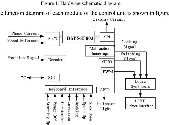
The function diagram of each module of the control unit is shown in figure 2.
PC
A/D
Decoder
SCI
PWM GPIO
SPI
IGBT Driver Interface GPIO
DSP56 F 803
Malfunction Ianterrupt
Figure 2. Control circuit schematic diagram.
[image:2.612.137.472.380.628.2]conversion module is to detect the signal of phase current, speed given, phase voltage and so on in real time.Use the hall position sensor built into the motor to detect the position of the motor and output 3 position signals.According to the position signal of the motor rotor, the channel sequence of IGBT is determined and the switch signal of IGBT is output.At the same time, the detection of the speed and phase current signal input DSP, according to the control algorithm to determine the PWM signal for the space ratio.The duty ratio of the PWM signal determines the speed control of the motor, which is the input of the logic integrated circuit along with the switch signal and the blocking signal generated by the fault interrupt.The output of the logic synthesis circuit is the input signal of IGBT drive circuit.
Electric operation principle
[image:3.612.161.439.367.434.2]Electric running, the current way of conduction with 120°conduction mode, namely the conduction time of every power tube is 120°electrical point of view.The speed regulating mode adopts the half-bridge modulation, which means that PWM only plays a role in a pair of components in the guide cycle.The switching state of the power tube depends on the HALL signal provided by the position sensor.When the motor is moving forward and backward, the relationship between the state of HALL position sensor and the open power tube is shown in table 1.
Table 1. The corresponding relationship between HALL state and Open power tube.
HALL state 110 100 101 001 011 010
Direct current
power tube T1T2 T1T6 T5T6 T5T4 T3T4 T3T2
Power tube in
reverse motor T5T4 T3T4 T3T2 T1T2 T1T6 T5T6
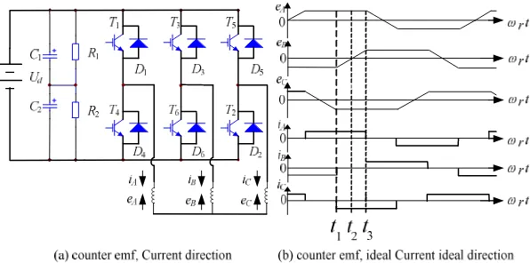
The corresponding relationship between phase current and counter potential is shown in FIG.3.Take the 60°time of T1 and T2,The waveform of eA,eBand eCis
[image:3.612.149.447.501.649.2]shown in FIG.3(b).The winding current of the switch tube and the closing time of the half-bridge modulation is shown in figure 4.
Figure 4. The winding current of a half-bridge. Software design
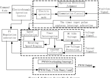
[image:4.612.122.479.322.572.2]The control unit of this design USES the MOTOROLA DSP56F803 chip, which USES C and assembler programming language to implement modular design.The structural block diagram of the system software design is shown in figure 5, which can be seen from the figure, the five modules of the program and the interrelation between each module's subroutine.
Figure 5. Software design block diagram.
signal output of the motor and the controller as short as possible, the signal line USES the twisted line and the method of using the outer shield signal line.Program can also exchange phase signal interference filter processing, namely, according to the speed of the motor in normal commutation position estimation of general period, outside the time period to block the interference signal, in this way, even if the rotor in the commutation near the point of interfering signal, can still normal commutation.
Experimental results and conclusions
[image:5.612.182.415.242.368.2]Figure 6 is the rotation speed curve of brushless dc motor in no-load start.It can be seen that the speed response is fast, the overtone is small, the speed fluctuation is small, and it has good dynamic and static characteristics.
Figure 6. The starting speed response curve.
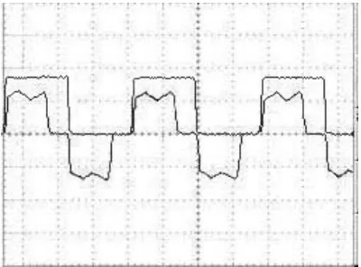
[image:5.612.198.398.452.600.2]The waveform of phase current and phase position signal controlled by the brushless dc motor controller is shown in FIG. 7.This waveform is ideal.The experimental results show that the system is in good condition and has certain application value.
Figure 7. The position signal and phase current waveform of A phase under electric operation.
References
1. Zhu Ying, Zhu Jun. Several kinds of PID control and simulation comparison, J. Industrial Control Computer 23(2010) 23 53-54.