2017 2nd International Conference on Computational Modeling, Simulation and Applied Mathematics (CMSAM 2017) ISBN: 978-1-60595-499-8
Directivity Control of a Microphone Array in the Vehicle Cabin
Wen-Kung Tseng
Graduate Institute of Vehicle Engineering, National Changhua University of Education, No. 1, Jin-De Road, Changhua City, Taiwan
Keywords: Directivity, Microphone array, Delay-and-Sum beamforming, Optimization method.
Abstract. Directional microphone can be used in the car. With the microphone, the driver may be under instructions to control the car audio system and information. Directional microphones make speech recognition accuracy to avoid receiving the other unwanted voice and external vehicle noise. This study investigates the directivity control of a microphone array used in the vehicle cabin communication system. Most of the literatures in the directivity control of a microphone array used the delay-and-sum beamforming method only. However a microphone array using 8 microphones combining the delay-and-sum beamforming with the optimization method is used in this work to control the directivity of the microphone array. Simulation results showed that the directivity of the microphone array could be improved significantly using the method proposed in this work.
Introduction
In the real world, there are filled with all kinds of noise and echo. These disturbances will seriously reduce the performance of speech recognition systems. In hands-free audio communication such as in car communications and conference room, how to make the microphone not receiving background noise is important. But in most situations speech signal quality is too poor to be received, especially when the speaker is at a far away from the microphone. The most effective way of increasing the signal-to-noise ratio (SNR) of a speech input system is to bring the microphone closer to the speaker but this may not be an ideal way [1, 2]. In this study array signal processing technique is used [3]. It can overcome the effects of environmental noise and echo of the voice signal and restore the clean voice signal. Most of previous works used the delay-and-sum beamforming to achieve the effect of the directional microphone array [4, 5]. In this study a novel method has been proposed to control the beamwidth of the main lobe and the level of the side lobe for the beam pattern by using an optimization technique. The results showed that the directivity of the sound beam for the microphone array could be controlled by the proposed method in the study.
Design of Directional Microphone Array
This study used the delay-and-sum beamforming combined with the optimization method. The delay-and-sum beamforming is to be accepted as a simple but powerful array signal processing algorithm [2, 3]. Assume that a group of M microphone, which is arranged in a uniform linear array (ULA) with an inter-element spacing of d. An observation point is set in the far-field of the array at an angle θ with respect to the normal of the microphone array aperture. If each microphone is weighted with a weighting, wn for n=0, 1, 2, . . ., M-1, the array response function can be derived as:
im M
n n w M
H
1
0
e 1
) (
. (1) where
= (d/c)sin is the time delay.
is the frequency.
n
is the angle with respect to the axis of the beam.
From Eq. 1, it shows that the maximum of the main lobe exists on the broadside of the ULA(=0). However, the maximum of the main lobe can be changed by adding a phase shift or delay to each microphone. If the ULA is to be steered in the direction 0, time delay (n0) has to be added to nth
microphone. The time delay 0 can be calculated as =(d/c)sin0, and the array response of the delay-and-sum beamforming becomes:
1 0 / ) sin (sin 0 1 ) ( M n c d im ne w MH
. (2) Then the Eq. 2 can be expressed as:
1 0 ) ( 0 1 ) ( M n jn ne w MH
. (3) Then the far-field directivity of the weighted primary sources array for frequency a, D1a() can be appeared: ) , ( ) , ( )
( 1 a a
la D k H k
D . (4)
Where D1(ka,) is the aperture directivity for frequency a, and the far-field array response
) , (ka
H is indicated in equation (1) with wam and a instead of wm and , similarly, the far-field directivity for primary frequency b with wbm instead of wam. Therefore, the beam pattern of the sound frequency can be expressed as:
) , ( ) , ( ) , ( ) , ( )
( D1 ka H ka D1 kb H kb
D . (5)
Generally speaking one microphone directivity can be expressed as[2]:
) cos( 5 . 0 5 . 0 ) (
D . (6)
Therefore the directivity of the microphone array can be expressed as:
1 0 ) ( 0 1 )] cos( 5 . 0 5 . 0 [ ) _( M n jn ne MD
. (7) Eq. 7 can also be expressed as:
1 0 / ) sin (sin 2 0 1 )] cos( 5 . 0 5 . 0 [ ) _( M n c d d jn ne MD
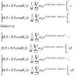
. (8) The formulation of the optimization approach proposed in the work for designing directivity microphone sound systems can be expressed as:
Minimize 2 2 2 2 2
1
)
_(
)
_(
D
D
Subject to
)
_(
)
_(
3D
1D
)
_(
)
_(
3D
2D
where
1 and
2 is the angle of the side lobe,
3 is the angle of the main lobe, is the predefined value between the main lobe and side lobes.Eq. (9) can also be expressed as: Minimize 2 2 1 0 / ) sin (sin 2 2 2 2 1 0 / ) sin (sin 2 1 0 2 0 1 1 )] cos( 5 . 0 5 . 0 [ 1 )] cos( 5 . 0 5 . 0 [
M n c d f jn n M n c d f jn n e M e M Subject to
1 0 / ) sin (sin 2 1 1 0 / ) sin (sin 2 3 0 1 0 3 1 )] cos( 5 . 0 5 . 0 [ 1 )] cos( 5 . 0 5 . 0 [ M n c d f jn n M n c d f jn n e M e M
1 0 / ) sin (sin 2 2 1 0 / ) sin (sin 2 3 0 2 0 3 1 )] cos( 5 . 0 5 . 0 [ 1 )] cos( 5 . 0 5 . 0 [ M n c d f jn n M n c d f jn n e M e M. (10)
The optimal values of n can be calculated using the function fmincon() in MATLAB. By substituting the optimal values of wn into Eq. 8, the directivity of the microphone sound beam
) (
_
D can be obtained.
Simulation Results
[image:3.595.68.319.148.402.2]the sum of the squared amplitude of the side lobe and subject to the amplitude difference between the main lobe and the side lobe.
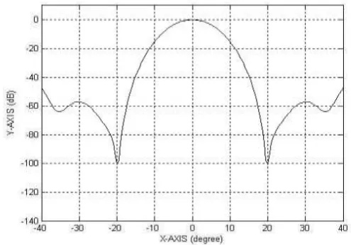
[image:4.595.175.417.337.531.2]Figure 1. Directivity for the microphone array with 8 microphones using delay-and-sum beamforming.
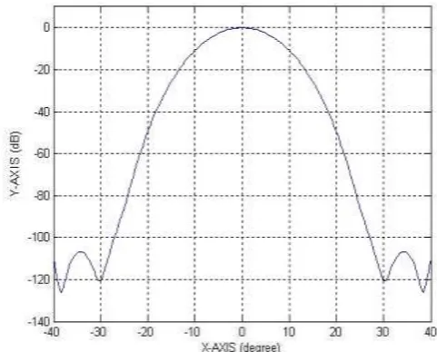
Figure 2. Directivity for the microphone array with 8 microphones for 300 using delay-and-sum beamforming
combined with optimization method.
Figure 3. Directivity for the microphone array with 8 microphones for 400 using delay-and-sum beamforming
[image:4.595.167.415.589.762.2]Figure 4. Directivity for the microphone array with 8 microphones for 600 using delay-and-sum beamforming
combined with optimization method.
Conclusions
This study investigated the performance of the directivity for the microphone array using the optimization method. The theoretical derivation of the directivity for microphone array has been presented. Also the formulation of the beam width control for the directional microphone array using optimization method has also been described. As can be seen from the simulation results the beam width of the directional microphone array could be controlled and the amplitude of the side lobe could be minimized using the optimization method.
References
[1] J. L. E. Kinsler, A. R. Frey, A. B. Coppens, J. V. Sanders, Fundamentals of Acoustics, John Wiley, 2000.
[2] M. Brandstein, D. Ward, Microphone Array: signal processing techniques and applications, Springer Verlag, 2001.
[3] D. H. Johnson, D. E. Dudgeon, Array Signal Processing: Concepts and Techniques, Prentice Hall, 1993.
[4] Roland Aubauer, Dieter Leckschat, Optimized second-order gradient microphone for hands-free speech recordings in cars, Speech Communication, 34 (2001) 13-23.