e e e e e
G
e
fa
0
G
e
G
G
--
0
0
G
fa
e
G
e
e
0 fa
0
0 It
G
G
e e
0
e
Q
Reference Drawing
A04-1
Collating List of Pages
This reference drawing contains the collating sequence. page side. and EC levet of pages for IBM 3480 Magnetic Tape Subsystem Maintenance Information Manllal (MI) Volume A04, SY32-5055-13.
The part number of the divider tab list is 8673746. PAGE SIDE LEVEL PAGE SIDE LEVEL
This reference drawing is to be placed at the front of the SDISK 131 Front EC 336395 DIAG 102 Front EC A57723
manual. SDrSK 135 Back EC 336395 DtAG 104 Back EC 336395
PAGE SIDE LEVEL PAGE SIDE LEVEL SDISK 140 Front EC 336395 DIAG 105 Front EC A57723
SDISK 145 Back EC A47957 DIAG 106 Back EC A57i21
FRONT COVER Front EC C13783 SPROC Tab SDISK 146 Front EC A57723 DIAG 110 Front EC AS7723
PREF 1 Back EC 336395 SDrSK 150 Back EC 336396 DrAG 112 Back EC A57723
SPROC 1 Front EC A5i723
TAB 1 Front EC 336395 SPROC 2 Back EC A5i723 SDISK 155 Front EC 336395 DIAG 114 Front EC AS7723
TAB 2 Back EC 336395 SDISK 160 B;:)ck EC 336395 DIAG 118 Back EC AS7723
SPROC 3 Front EC 336395
LGND Tab SPROC 4 Back EC A57723 SDISK 165 Front EC A47957 DrAG 120 Front EC A57723
SDISK 170 Back EC 336396 DIAG 124 Sack EC ~S7723 LGND 1 Front EC 336395 SPROC 100 Front EC A57723
LGND S Back EC 336395 SPROC 110 Back EC A57723 DIAG Tab DIAG 150 Front Er' _ ~"-10t; v,Jc ... ~
DIAG 152 2ack - r-t: ... ...;vvv .... -:-:::"'0::: ·J LGND 10 rront EC 336396 SPROC 120 Front EC AS7723 DIAG 1 Front EC A57723
LGND 15 Back EC 336396 SPROC 130 Back EC AST,n DIAG 2 Back EC A57723 DIAG 160 ;:ront ~r __ "J"" ... .... ",;:::10::: DIAG 162 Back EC 336395
LGND 20 Front EC 336395 SPROC 140 Front EC AS7723 DIAG3 Front EC A57723
LGND 25 Back EC 336395 SPROC 150 Back EC A57723 DIAG 4 Back EC 336395 DIAG 164 ~ront EC 336395
DIAG 155 Sack EC 336395
LGND 30 Front EC 335395 SDISK Tab DIAG 5 Front EC 336395
LGND 35 Back EC 336395 DIAG6 Back EC 336395 DIAG 170 Front EC 336395
SDISK 1 Front EC 336395 DIAG 200 Back EC AS7593
LC;~: Co 40 Frorot EC 336395 SDISK 100 Back EC 336395 D!AG 7 Front EC 336395
i..GND 45 Back EC 336395 DrAG 20 Back ES 336395 DIAG 202 Front EC A57724
SDISK 105 Front EC A57i24 DIAG 204 Back EC A57693
LGND 46 Front EC 336395 SDISK 110 Back EC 336395 DIAG 30 Front EC 336395
LGND 47 Back EC 336395 DIAG 32 Back EC 336395 DIAG 206 Front EC A57593
SDISK 111 Front EC 336396 DIAG 208 Back EC 336395
LGND 48 Front EC 336396 SDISK 115 Back EC A57724 DIAG 34 Front EC 336395
LGND 50 Back EC 336396 DIAG 50 Back EC 336395
SDISK 116 Front EC A57i24
LGND 55 Front EC 336395 SDISK 120 Back EC 336396 DIAG 55 Front EC 336395
LGND 60 Back EC 336395 DIAG 60 Back EC 336395
SDISK 121 Front EC 336396
LGND 65 Front EC 336396 SDISK 125 Back EC 336396 DIAG 65 Front EC A57i23
LGND 70 Back EC 336396 DIAG66 Back EC A57i23
SDISK 126 Front EC 336395
LGND 75 Front EC 336395 SDISK 130 Back EC 336395 DrAG 70 Front EC A57723
LGND 80 Back EC 336395 DIAG 100 Back EC 336395
Ref.erence Drawing
A04-1
.
)
Collating List of Pages
PAGE DlAG 210 OIAG 212 DIAG 214 DIAG 218 DIAG 219 DIAG 220 DIAG 222 DIAG 224 DIAG 226 DIAG 228 DIAG 229 OIAG 300 DIAG 301 DIAG 302 DIAG 304 DIAG 306
DIAG 308 DIAG 310 DIAG 312 DIAG 320 DIAG 321 DIAG 322 DIAG 323 DIAG 324 DIAG 326 DIAG 328 DlAG 330 DIAG 332 DIAG 334 DIAG 336 DIAG 338 DIAG 340 DIAG 342 OIAG 344 3480 MI SIDE Front Back Front Back Front Back Front Back Front Back Front Back Front Back Front Back Front Back Front Back Front Back Front Back Front Back Front Back Front Back Front Back Front Back j LEVEL EC 336395 EC 336395 EC 336395 EC A57693 EC A57693 EC 336395 EC 336396 EC 336396 EC 336396 EC 336396 EC 336395 EC A57724 EC A47957 EC A47957 EC 336395 EC 336395 EC 336395 EC 336395 EC 336395 EC 336395 EC 336396 EC 336396 EC 336396 EC 336396 EC 336395 EC 336395 EC 336395 EC 336395 EC 336395 EC 336395 EC 336395 EC 336395 EC 336395 EC 336395 \ j PAGE DIAG 346 DIAG 348 DIAG 400 DIAG 402 DIAG 410 DIAG 412 DIAG 450 DIAG 452 DIAG 454 DIAG 460 DIAG 462 DIAG 500 DIAG 501 DIAG 502 DIAG 503 DIAG 504 DIAG 506 DIAG 508 DIAG 509 DIAG 510 DIAG 511 DIAG 512
DIAG 514 DIAG 516 DIAG 518 DIAG 520 DIAG 522 DIAG 524 DIAG 526 DIAG 528 DIAG 530 DIAG 532 DIAG 534 DIAG 536
}
SIDE Front Back Fro:)t Back Front Back Front Back Front Back Front Back Front Back Front Back Front Back Front Back Front Back Front Back Front Back Front Back Front Back Front Back Front Back LEVEL EC 336395 EC 336395 EC A57723 EC 336395 EC 336396 EC 336396 EC 336396 EC 336396 EC 336395 EC 336395 EC 336395 EC 336395 EC 336395 EC 336395 EC 336396 EC 336396 EC 336395 EC 336395 EC 336395 EC 336395 EC 336395 EC 336395 EC 336395 EC 336395 EC 336395 EC 336395 EC 336396 EC 336396 EC 336395 EC 336395 EC 336395 EC 336395 EC 336395 EC 336395 !,
)
PAGE OIAG 538 OIAG 540 OIAG 542 OIAG 544 OIAG 550 OIAG 551 OIAG 552 OIAG 554 OIAG 556 DIAG 558 OIAG 560 OIAG 562 OIAG 564 OIAG 566 OIAG 568 DIAG 570 DIAG 572 DIAG 574 OIAG 576 DIAG 578 DIAG 580 DIAG 582 DIAG 584 DIAG 586 DIAG 600 OIAG 605 DIAG 610 DIAG 615 OIAG 620 OIAG 720 OIAG 721 OIAG 722 OIAG 725 OIAG 755 SIDE Front Back LEVEL EC 336396 EC 336396Front EC 336395
Back EC 336395
Front EC C13783
Back E C 336395
Front EC 336395
Back EC C13783
Front EC 336395
Back E C 336395
Front EC 336395
Back E C 336395
Front EC 336396
Back EC336396
Front E C 336395
Back E C 336395
Front EC 336395
Back EC 336395
Front EC 336395
Back EC 336395
Front EC 336396
Back E C 336396
Front EC 336395
Back EC 336395
Front EC A57723
Back EC 336396
Front EC 336395
Back EC 336395
Front EC 336395
Back E C A57723
Front EC A47957
Back EC 336396
Front EC A57693
Back E C 336395
,
#
PAGE
OF Tab
OF 1 OF 3
OF 5 OF 10
OF 12 OF 15
OF 20 OF 25
OF 30 OF 33
OF 35 OF 36
OF 37 DF 40
DF 45 DF 50
OF 55 OF 60
DF 62 DF 65
DF 70 OF 75
OF 80 OF 82
OF 85 OF 88
OF 88-1 OF 88-2
OF 90 OF 95
OF 100 OF 105
Reference Drawing
A04-2
SIDE LEVEL
Front E C A57723
Back EC 336395
Front EC A57723
Back E C 336395
Front EC A57723
Back EC 336395
Front EC 336395
Back EC 336395
Front EC 336395
Back EC 336395
Front EC 336395
Back EC A57723
Front EC A57723
Back EC 336395
Front EC A5024
Back EC 336395
Front EC 336395
Back EC A57;"21
Front EC 336395
Back EC 336395
Front EC 336396
Back EC 336396
Front EC 336395
Back EC 336395
Front E C 336395
Back EC A5i723
Front EC A57723
Back EC A5i723
Front EC 336395
Back EC 336395
Fmnt EC 336395
Back EC 336395
Reference Drawing
A04-2
e e
e e e
G G
G
C
C
G
0
C
Q
C
(l
C
C
C
C
C
G
C
G
G
C
C
C C
G G
Q
G C
Collating List of Pages
Reference Drawing
A04-3
PAGE SIDE LEVEL PAGE SIDE LEVEL PAGE SIDE
LEVEL
DF 110 Front EC 336395 OPER 95 Back EC A57693
DF 115 Back EC 336395 OPER 230 Back ECA57723
OPER 96 Front EC 336395
DF 117 Front EC 336395 OPER 100 Back EC A57723 OPER 240 Front EC A57693
OF 120 Back EC A57723 OPER 245 Back EC A4795?
OPER 105 Front EC 336395
DF 125 Front EC 336395 OPER 106 Back EC 336395 RCF-l Front
DF 130 Back EC 336395 RCF-2 Back
OPER 110 Front EC 336395 OF 135 Front EC 336395 OPER 115 Back EC A57693 OF 140 Back EC 336396
OPER 120 Front EC 336396 OF 145 Front EC 336396 OPER 125 Back EC 336396 OF 150 Back EC 336395
OPER 130 Front EC 336395 DF 155 Front EC 336395 OPER 131 Back EC 336395 DF 160 Back EC A57721
OPER 135 Front EC 336395
OPER Tab OPER 140 Back EC 336395
OPER 1 Front EC 336395 OPER 141 Front EC 336395 OPER 2 Back EC A47957 OPER 142 Back EC 336395
OP::R 5 Front EC 336396 OPER 145 Front EC 336395 OPER 10 Back EC A57721 OPER 150 Back EC 336395
OPER 15 Front EC 336395 OPER 155 Front EC A57723 OPER 20 Back EC A57723 OPER 160 Back EC 336395
OFER 25 Front EC A57693 OPER 165 Front EC A57723 OPER 30 Back EC A57693 OPER 170 Back EC A57723
OFER 35 Front EC 336395 OPER 175 Front EC 336395 OPER 40 Back EC 336395 OPER 180 Back EC 336395
OPER 45 F"cnt EC 336396 OP~R 185 Front EC 336395 OPER 50 Back EC 336396 OPER 186 Back EC 336395
OPER 55 Front EC 336396 OPER 187 Front EC 336395 OPER 60 Back EC 336396 OPER 188 Back EC 336395
OPER 65 Front EC 336395 OPER 190 Front EC 336395 OPER 70 Back EC 336395 OPER 196 B'-Ick EC 336395
OPER 75 Front EC 336395 OPER 200 Front EC 336395 OPER 80 Back EC 330395 OPER 205 Back EC 336395
OPER 81 Front EC 336396 OPER 210 Front EC 336395 OPER 85 Back EC C13783 OPER 215 Back EC 336395
OPER 90 Front EC A57723 OPER 220 Front EC A57723
3480 PN 8673721
MI 3 of 3
Reference Drawing
A04-3
-to;
L()
to
o
~
t'-to
CO
I
PUBLICATIONS REFERENCE DRAWING
MACHINE TYPE/MODEL NO. 3480
MACHINE NAME - Magnetic Tape Subsystem
- - - . - ----r---
---,.--.---FORM NO.
SY32-5055-0
E C NO.
I
DESCRIPTION/COMMENTS
991552
336326
VOL.
A04 - Maintenance Information
REA 12-11655
TNL SN32-0310
IEC 001122571 (REA 12-25744)
IEC 002122571 (REA 12-25494.
REA 12-25496)
8674065
. ---.----..
---SY32-5055-1
336389
Second Edition
IEC 0011215156
IEC 0011225996
---_·_---_·_---·1- . - - - -.. - .... -.. -... - ... -- ... .,.-..
--.---.----.--SY32-5055-2
336390
Third Edition
lEe 0011225997
IEC 0011215157
1 - - - 1 - ----.--.
-SY32-5055-3
336391
Fourth Edition
REA 77-11223
IEC 0011215158
IEC 0011215159
IEC 0011225842
IEC 0011225843
-·----·---I·---l---.... -.-.-.... --..
----.---.-.-SY32-5055-4
336392
I
Fifth Edition
IEC 0011225998
IEC 0011228481
-·1- -1 .... .... .... ... . .
-336393
TNL SN32-5036
- - - - --.---.-- ---.--
---_._---S Y32-5055-5
336394
Sixth Edition
- - - 1--·_· .• . .... .. .... , .
-SY32-5055-6
336395
Seventh Edition
IEC 0011225844
1 - - - 1 - - - 1 .-.--.--.--.-.--.... -... - - - - .
SY32-5055-7
SY32-5055-8
336396
Eighth Edition
IEC 0011222986
A47957C
I
Ninth Edition
- - - 1
I
.. -.. -... -.-.--.---
--1
SY32-5055-9
A57693
I
Tenth Edition
I
SY32-5055-10
A57721
Eleventh Edition
SY32-5055-11
A57723
Twelfth Edition
I
. - - - . - - . - - - . - - - lSY32-5055-12
A57724
Thirteenth Edition
- - - -.. 1 - - - 1 - - - _ · __ .. _·_-_ .. _- --I
SY32-5055-13
C 13783
I
Fourteenth Edition
L -_ _ _ _ _ _ _ _ _ _ _ _ _ _ L-_
IBM
DATE CHANGE NO DATE CHANGE NONAME.
I
PUB REF OWG (PRO)
I
REL
See EC
History
OJ
m
"-J.7/24/89
A57723
DESIGN
I
,SHT OFDETAIL
1
5/11/90,
'I
A57724
1
--I
~
9/30/91
C 13783
m
0'1
CHECK MUST CONFORM TO ENG SPEC DeVELOPMENT NO LOGIC PG NO
APPRO
RD004
CD
--.
. j . . .
-"""""
~~~~~,
"n· ...
--....
...
'
...
-... ~~
. ",
....
"..,-M, ...
-'"
~
-,....,
....
-
,--~t-~¥ . .
...
...
-"""~'* ...
-~.l 1",...
~
...
'"
--~-....
-e
e
c e c c c c c c c c c c
3480 Magnetic Tape Subsystem
c c c c
~
0 G
~
C C
Gee C eGG G G C
-~-
---
-
-
- - - -
--
. .
--
-
----
-
-
----
_
..
--~-.-
Maintenance lriformation
3480 3480
SIN-
S/N-HI MI
Maintenance Maintenance
Information Information
GLOSS PWR
PLAN SENSE
INTRO PANEL
*START* MD
CART LOe
PNEU eARR-eU
HSG INST INSP INDEX
Vol AOI Vol AOZ
Maintenance Library
Maintenance Infonnation
Logic Diagrams
3480 3480
S/N-
SIN-MI MI
Maintenance Haintenance
Information Information
eARR-QB LGND
SPROe SDISK DIAG OF OPER
Vol A03
I
Vol A04I
Vols. A01 to AOS
Vols. C01 and 001
3480
S/N-MI Maintenance
Information
FSI EAD
Vol AOS
Preface
This manual contains maintenance information about the IBM 3480 Magnetic Tape Subsystem and is intended for customer engineers responsible for servicing the 3480 tape subsystem. This publication is designed to be used with the IBM
Maintenance Device (MOl. Therefore. CEs using this manual should be familiar with that tool.
Prerequisite Knowledge
It is assumed that you have a background in data processing concepts and that you are familiar with the hexadecimal numbering system. stored program concepts. and have a basic understanding of tape subsystems and their relationship to a processor I/O channel.
3480 MI EC336395
C> C""",ogh' IBM Corp. 1984 1985. 1986
Related Publications
IBM System/360 and System/370 I/O Interface Channel to Control Unit Original Equipment Manufacturers' Information.
GA22-6974.
IBM 3480 Magnetic Tape Subsystem Description, GA32-0042.
How to Update the Maintenance
Information
This manual is form number controlled. The 3480 manuals will be updated by Technical Newsletters (TNLs). The TNL cover letter will indicate the new EC level. The entire manual will be updated by major revision. All updates are processed through normal MLC control. The Publications Reference Drawing (PRO) in the front of each volume contains the EC history.
J
.
~How to Order This Manual
This manual or pages can be ordered from one of the following:
• United States
• Europe/Middle East/Asia IE/ME/A)
• Americas/Far East (A/FE)
Use the wiring Diagram/Logic Page Request form. Z 150-0 130. Be sure to include the form number of the manual when ordering the new manual or pages. Please write your telephone number on the form in case there are any questions regarding your order.
United States
IBM Corporation
General Products Division Dept.3Ot..
Tucson. Arizona 85744
E/ME/A
International Business Machines S.A.E .• Division de Fabricacion Dept. 9290
Valencia. Spain
A/FE
IBM Argentina SA Dept. 020 H. Yrigoyen 2149 1640
Martinec. Pcia. Buenos Aires Republic of Argentina
Preface
PREF 1
Preface
PREF 1
l
o
o
()
o
o
CJ
o
o
o
Tab List
Tab List
TAB 1
Volume A01
Volume A02
Volume A03
Volume A04
GLOSS Glossary PWR Power Maps CARR-DR Drive Checks/ Adjustments/Removal/Replacement LGND Legend
PLAN Maintenance Plan SENSE Sense/Status SPROC Support Procedures
INTRO 3480 Introduction PANEL Panel SDISK Support Diskette Procedures
START Start Maintenance MD Maintenance Device DIAG Support Diagnostic Descriptions
CART Cartridge Analysis LOC Locations OF Data Fields and Registers
PNEU Pneumatic Analysis CARR-CU Control Unit OPER Theory of Operation
Checks/ Adjustments/Removal/Replacement
MSG Console Messages and EREP
INST Installation/Removal
INSP Safety Check Procedures
INDEX Index
Volume A05
FSI Fault Symptom Index
EAD Error Analysis Diagrams
3480 MI EC336395
Tab List
TAB 1
Notes
Notes
TAB 2
3480 MI EC336395
Notes
TAB 2
'" Copyrlgl\.IBM Corp. 1984. 1985. 1986
. j
}
I
\
G
o
Contents
Graphic Symbols and lines . . . 5
Ke~ . . . 5 Connectors .... " .. , .... , . . . , .. ,.,." .. , . . . , .. , .. , . " . 5 Bus and Control lines , ... , . . . , ... ,.,., ... ,., . . . ,' . . . , .. " . . . . 5 IdentifYing Parts , ... ,., .. , ... , . . . , . . . " ... , .. . Control Unit Location Area Definitions ,.,., .... , ... " . , .... , . . . " . , . " .... . Tape Unit and Drive Location Area Definitions ., . . . " . . . " ... , .... ,., .... ,. Error Analysis Diagram Logic Blocks , .. , ... , . , . , . , . . . , .... ,.,., . . . . Logic Diagrams " . , . , .... , ... , ... , . . . ,., . . . . Card Location Charts ... " . . . , ... , . . . , . . . , .... , . . . . Card Plug lists . . . , . . . , . . . , .. Multiple Logic Diagrams for One Card , . . . . Sample Logic Diagram ... , . . . ,., . . . , Bundled Lines , . . . , . . . , . . . . Logical/Physical Pins . . . , . . . , . . . . Dot OR' s of Output lines . . . .... , . . . . Field Wire Net lists . . . .
Pin to Net list Net to Pin list
... ...
Voltage Distribution list . , , .. , . . . .
3480 MI EC336395
<I> CopyrIght IBM Corp. 19B4, 1985
10
15 35
55
60 60 60 60
65
70 70 75
80 80 80 80
o
c
o
Contents
LGND
1
Legend
Graphic Symbols and Lines
Keys
Primary Key
Reverse number in a black square. Used in text and diagrams.
Secondary Key
Reverse letter in black circle. Used in text when keying to a test point symbol in a diagram.
Connectors
On-Page Connectors
Connection between parts of the same diagram. Arrows point to remote connectors and indicate flow direction of the line.
Off-Page Connectors
Connection between diagrams on separate pages. Letter keys are used to identify corresponding points.
3480 MI
Page ~ Entering Page Number
'-=-'
Leaving Page ~ --'-;~-1LY
EC336395
~ Copyr'gh! IBM Corp. 1984. 1985
Page Number
Legend
LGND 5
Bus and Control Lines Bus and control lines that connect to a bus.
Minor Bus Lines
Write Data
~
B Read Bus
..
Device Data Bus~
Major Bus Line
Bus and control lines that do not connect to a bus.
Control lines
Not Connected Standard line break, used when a line break is needed.
Connected
---~ss~---Bus or cable with multiple control lines entering and exiting .
•
"
..
Legend
LGND 5
o
c
Legend
Identifying Parts
Two different formats are used in the maintenance information (MI) and logic diagrams to represent the unit that a part is located.
Examples of the First Format:
lA-A1H4 1 A-A 1D2-U06 1 A-A 1 E2-W22 lA-A2G2 2A-A1C2
Control Uni t Logic Par t Deflnili\)ns lA-A2G2
- - U U
~
~[ord
or connectorBoord
Got@ From.
T(:Ipe Unit Logic Port Definitions 2A·AIC2
-- u u
~l
~Lord
or .t3oord - - G o O l eFrome
("onnec: tor
Ignol0a
Logie Board Card Pin Position Identifiers
IA-AID2-U06 U
t
Logic card and board pin U06 of the IA-AID2 board position (this is the pin connection between the logic board and the logic card bottom card connector (Bee) or other connector in that position.Logic Board Card Pin Position Identifiers
IA-AIE2-W22 U
3480 MI
t
Logic card top card connector (Tee) pin W22 for the logic card in positionIA-AIE2 (the Tee is a card to card connector located on the non-pin side of the card and provides for card to card connect ions or a single wide Tee connects Tee card pins within a card.
EC336396 © Copyrignl IBM Corp 1984. 1985; 1986. 1987
(ctd Connec..lor Pfn6 (VIew from end of cardl
D02- . • _B02 0 3 - . 03
0 4 - . Oq
0 5 - • 05
0 6 - . 06
0 1 - . 07
0 6 - . 08 0 9 - . 0"1
1 0 - . 10 1 1 - ' 11 1 2 - . 12 D13- • • -!l13
I..~ J 0 2 -
W-
U0 2 J I 3 - U _ GI3P 0 2 - b j _ M 0 2
P 1 3 - U - M I 3
U 0 2 - k j - S 0 2
U I 3 - D - S I 3
o
Card (onn.Llor Pln5
(Vr.~ (rom end of cord
(02A-A1B2 cord only)
C02
0 0 2 - ••• -B02 0 3 - ••• - 03
O q - ... - 0<1
0 5 - ... ....- as 0 6 - ' " - 06 0 7 - ... - 07 0 8 - ••• - 08 0 ' 3 - ... - 0"1 1 0 - ' " - 10 1 1 - " ' - 11 1 2 - ' " - 12 0 1 3 - ... -!l13
Cl3
J02
-ffi-
G02 J I 3 - r - GI3~t;
P02
-ffi-
10102PI3-~_MI3
N.3
T02
U02
-ctJ-
502UI3-<>r.1""'513
~
Igndl0b
o
Top cord CO"""_C.tor (TCC) pins
(V,.'" from 11"1_ top of the c.ard)
w22- • -w02 2 3 - • 03
2L.4- • 04 2 S - . OS 2 6 - . 06
2 7 - 07 2 8 - . 08
2 ' 3 - . 0'3 3 0 - . 10 3 1 - . II 3 2 - 12
wJ3-- • _H13
X 2 2 - D - X 0 2
X 3 3 - U - XI3
Y 2 2 - D - Y 0 2
Y33-LJ_\"I3
Z 2 2 - D - Z 0 2
Z 3 3 - L J - Z I 3 IgndlOc
Examples of the Second Format:
lA-T1A 1 lA-T1A3Y 2A-A1Z2 lA-A2Y2 CU-P2A4 CU-PS-Ol-Jl-3 CU-UR-P2-2 CU-A 1-TB3-6 CU1APl-3 TU-OO-PA-Jl-012 TU-D1-PA-J1-D12 TU-001D1-A 1-Cl B 11 TU-001D1-Pl-3 TU-00/Ol-0K-P7-4 TU-DO-EL-J7-1 TU-D1-DSP-P1-011 TU-PS-Ol-P11-3 TU-PS1-J2-9 TU-OO-P 1-WA2-005 TU-Ol-Al-A2-B12 Subsyslem Unilidenliliers lA-... . CU-... . 2A-... . TU-... .
Control unit Control unit Tape unit Tape unit
Tape Drive Unll Idenllflers
o
For subsystems unit with identifiers of TU or 2A only.
TU-OO ....
TU-Ol ....
TU-OO/Dl
2A-OO/Ol
(J
o
o
Legend
LGND 10
2A-. (when no DO or 01)
or
TU-... The next numbers are the functional
area within the tape unit. nolthe individual drives within the tape unit.
TU-DO-.. Drive 0 - the remaining numbers pertain to FRUs or parts in drive O.
TU-Dl-.. Drive 1 - the remaining numbers pertain to FRUs or parts in drive 1.
TU-DO/Dl-.. Drive 011 - the remaining numbers
pertain to FRUs or parts in both drive 0 and drive 1.
Logic Locallon Area Identifiers
lA- TlAl ... TU-DO/Dl-Al ...
CU-P2A4 ... TU-DO/Dl-Pl-Pl ...
CU-PS-Ol ... TU-DO/Dl-DK ...
CU-L/R-P2 ... TU-Ol-DSP ...
CU-Al-TB3 ... TU-PS-Ol ...
TU -DO-~tSG ... TU-DO-Pl-WA2 ...
Nole: For descriptions. locations, and remove/replace
procedures for the location area identifiers, see the following for:
• Control unit - "Figure 1. Control Unit Location Area
Definitions"
• Tape unit and tape drives - "Figure 2. Tape Unit and
Drives Location Area Definitions"
Part Locallon Idenllflers
CU-PS-Ol-Jl-3 CU-L/R-P2-2 TU-DO/Dl-Al-ClBll TU-PS-Ol-Pll-3 TU-PSl-J2-9 TU-DO-Pl-WA2-D05
(pin 3 of connector Jl)
(pin 2 of connector P2)
(pin Bll of position Cl)
(pin 3 of connector Pll)
(pin 9 of connector J2) (pin DOS of connector WA2)
Legend
The following figures show how to locate parts In the 3480 documentation, uSing the identifying numbers that are shown in "Examples of the Second Format" on LGND 10.
For the part location area that IS used in the logics, the figures show where they are located In the 3480 subsystem by referencing the "Table of Contents" entry In the LOC and CARR sections of the Maintenance Information. The LOC and CARR sections "Table of Contents" may not be the exact name or FRU number of the part referenced in the logiC, however the page referenced by the "Table 01 Contents" will relate to the part you are looking for.
These figures also show where a part can be found in the logiCS. For example, if the power is suspected to be a problem, you can look for power parts (CBs, Power Supplies, and so forth) and find the logic pages that show these areas.
Control Unit location Area Definitions
LOGIC
LOCATION LOC 1 CARR I
AREA LOGIC TABLE OF CONTENTS TABLE OF CONTENTS
IDENTIFIER DESCRI PTION PAGE REFERENCE REFERENCE
lAP I Connectors YFOO5 Fan Assemblies FRU165
for gate fans I and 2
+24v Servi ce switch ZT020 CU-AI Logic Gate FRUl62
Service (Hinge Side)
Switch
Al Logi c board AAOOO OIA-AI Logic Board FRUl39
AAIOO
AIA2 Logic board AAOOO OIA-AI Logic Board FRUl39
pos it i on A2
AIY2 Logic board AAOOO OIA-AI Logic Board FRUl39
connector Y2 at top of board
AIZ2 Logic board AAOOO OIA-AI Logic Board FRU139
connector at bottom of board
AIP2Y Single wide TCC AAOOI OIA-AI Top Card FRUI8I
board position P2 Connectors and Cables
row y
AIYCDE TCC row y AAOOO OIA-AI Top Card FRUl93
across board Connectors and Cables
positions C-E
AIZFG TCC row Z AAOOO OIA-AI Top Card FRUl87
across board Connectors and Cables
positions F-G
A2 Logi c board AAOOI OIA-A2 Logic Board FRUI40
AA200
A2A2 Log i c board AAOOI OlA-A2 Logic Board FRU140
position A2
A2C2W Single wide TCC AAOOI OlA-A2 Top Card Cables FRUI70
board position C2 CAOO2
row \oj WAOO5/006
3480 MI EC336396
Legend
LGND 15
LOGIC
LOCATION LOC I CARR 1
AREA LOGIC TABLE OF CONTENTS TABLE OF CONTENTS
IDENTIFIER DESCRIPTION PAGE REFERENCE REFERENCE
A2C2W22 Single wide TCC AAOOI OIA-A2 Top Card Cables FRUI70
board position C2 CA002
row W, pin 22 WAOO5/006
A2Y2 Logic board AAOOI OlA-A2 Top Card Cables FRU140
connector Y2 at top of board
A2Z2 Logic board AAOOI OlA-A2 Top Card Cables FRUl40
connector Z2 at bottom of board
Diskette Diskette drive WZOOl/OO2 Operator Set Up Panel FRU086
Drive
Fans Gate fans YFOO5 Fan Assembly 1 FRUl50
(Gate) Fan Assembly 2 FRU151
L/R Local/remote YFOZO Operator Set Up Panel FRU084
power panel
-J I Connector YF020 Operator Set Up Panel
-J2 Connector YF020 Operator Set Up Panel
Local Loca I power YF020 Operator Set Up Panel
Power enable
Enable
MD CU connector for WXOOI MD Connector FRUl69
Connector MD attachment
--OP Operator panel Operator Set Up Panel FRU142
-JI/J2 Connector WZlO6
-J2/P2 Connector WZlO6
-J5 Connector YFOl5 Operator Set Up Panel FRUl42
WZlO6
-Power Power on YFOl5 Operator Set Up Panel FRUl42
On- indicator
Indicator
-(Sub) (Sub) system YFOl5 Operator Set Up Panel FRUl42
System power switch
Power Swi tch
-UEPO UEPO switch HOl5 Operator Set Up Panel FRUl98
Switch
0
G
C
()
C
C
C
C
C
0
Legend
legendLGND 20
Control Unit location Area Definitions (Continued) LOGIC
LOCATION LOC 1 CARR 1
AREA LOGIC TABLE OF CONTENTS TABLE OF CONTENTS
IDENTIFIER DESCRIPTION PAGE REFERENCE REFERENCE LOGIC
LOCATION LOC 1 CARR 1
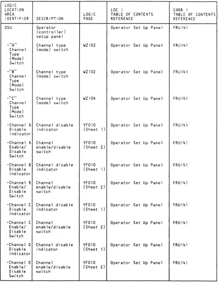
-CUO/CUl CUO/CUl sw itch YF010 Operator Set Up Panel FRU197 Swi tch
AREA LOGIC TABLE OF CONTENTS TABLE OF CONTENTS
IDENTIFIER DESCRIPTION PAGE REFERENCE REFERENCE
-CU "A" Channel address WZ102 Operator Set Up Panel FRU197 Address sw itch
Switch OSU Operator Operator Set Up Panel FRU141
(controller) setup panel
-CU "B" Channel address WZ102 Operator Set Up Panel FRU197 Address sw itch
Switch _"A" Channel type WZI02 Operator Set Up Panel FRU141
Channel (mode) switch Type
(Mode)
Sw itch -CU
"c"
Channel address wZl04 Operator Set Up Panel FRU197Address switch Switch
_"B" Channel type WZ102 Operator Set Up Panel FRU141 Channel (mode) swi tch
-CU "0" Channel address WZ104 Operator Set Up Panel FRU197 Address switch
Switch Type
(Mode) Switch
-CU Error CU error indicat- YF010 Operator Set Up Panel FRU141 Indicator or
-CU Onl ine CU onl ine switch YF010 Operator Set Up Panel FRU141 Switch
_"C" Channel type WZ104 Operator Set Up Panel FRU141 Channel (mode) switch
Type (Mode) Switch
-CU CU wait indicator YF010 Operator Set Up Panel FRU141 Waiting
Indicator -Channel A Channel disable YF010 Operator Set Up Panel FRU141
Disable indicator (Sheet 1 ) Indicator
-"D" Channel type WZ104 Operator Set Up Panel FRU141 Channel (mode) switch
Type (Mode) -Channel A Channel YF010 Operator Set Up Panel FRU141
Enable/ enable/disable (Sheet 2) Disable switch
Swi tch
Switch
-DC Power DC power on YF010 Operator Set Up Panel FRU141 On indicator
-Channel B Channel disable YFOIO Operator Set Up Panel FRU141 Disable indicator (Sheet 1 )
Indicator
Indicator
- I ML!Power IML/power on YF010 Operator Set Up Panel FRU141 On Reset reset switch
Swi tch -Channel B Channel YF010 Operator Set Up Panel FRU141
Enable/ enable/disable (Sheet 2) Disable switch
Switch
-Jl/Pl Connector WZ106 Operator Set Up Panel FRU141 YF010
(Sheets -Channel C Channel disable YF010 Operator Set Up Panel FRU141
Disable indicator (Sheet 1 ) Indicator
1 and 2)
-J2/P2 Connector WZ106 Operator Set Up Panel FRU141 YF010
(Sheets -Channel C Channel YF010 Operator Set Up Panel FRU141
Enable/ enable/disable (Sheet 2) Disable switch
Switch
1 and 2)
-n/P3 Connector YF010 Operator Set Up Panel FRU141 (Sheet 2 )
-Channel D Channel disable YF010 Operator Set Up Panel FRU141 Disable indicator (Sheet 1)
Indicator
-J4/p4 Connector YF010 Operator Set Up Panel FRU141 (Sheet 2 )
-Channel D Channel YF010 Operator Set Up Panel FRU141 Enable/ enable/disable (Sheet 2 )
Disable switch
-J5/P5 Connector for YF010 Operator Set Up Panel FRU141 thermal jumper (Sheet 2)
Switch
3480 MI EC336395 legend
LGND 20
[image:13.1227.70.522.131.708.2]Legend
Control Unit Location Area Definitions (Continued)
LOGIC LOCATION
AREA LOGIC
IDENTIFIER DESCRIPTION PAGE
-Local Local power YF010 Power enable switch
Enable Switch
-Offline Offline indicator YF010 Indicator
-Test/ Test/Normal YFOIO Normal switch
Switch PI -AI -A2 -Bl -B2 -JI P2 -AI -A2 -A3
-A4
3480 MI
Cable panel
Connector WT004 WTo06 WW020
Connector WTOOI WW010
Connector WW020
Connector WW010
Thermal connector YF015
Cable panel
Connector Connector Connector Connector EC336395 WW020 WTo08 WT010 WW020 WK005 WW010 WKOOI WK003 WK005 WW010
1) CopYright IBM Corp. 1984. 1985
LOC 1
TABLE OF CONTENTS REFERENCE
Operator Set Up Panel
Operator Set Up Panel
Operator Set Up Panel
CU-Pl Read/Write Bus Connectors
CU-Pl Read/Write Bus Connectors
CU-Pl Read/Write Bus Connectors
CU-PI Read/Write Bus Connectors
CU-Pl Read/Write Bus Connectors
CU-Pl Read/Write Bus Connectors
CU-P2 Cable Connectors (Dual Control Unit
Communication Connectors)
CARR 1
TABLE OF CONTENTS REFERENCE FRUI41 FRU141 FRU141 FRU150 FRU150 FRU150 FRUI50 FRUI50 FRU150 FRU150
CU-P2 Cable Connectors FRUI50 (Dual Control Unit
Communication Connectors)
CU-P2 Cable Connectors FRUI50 (Dual Control Unit
Communication Connectors)
CU-P2 Cable Connectors FRUI50 (Dual Control Unit
Communication Connectors)
CU-P2 Cable Connectors FRUI50 (Dual Control Unit
Communication Connectors) \
J
LOGIC LOCATION AREA IDENTIFIER -A5 PS-OI -CBI -CB2 -CB3 -Fl -Jl-J4B -J9-Jl0 -J 11 -JI3-JI5 PS-02 -CBl -CB2 -CB3 -Fl -F2 -Jl-J20 -Kl Tl T1AI TIA3YLegend
LGND 25
LOC 1 CARR 1
LOGIC TABLE OF CONTENTS TABLE OF CONTENTS
DESCRIPTION PAGE REFERENCE REFERENCE
Connector WK006 CU-P2 Cable Connectors FRU150 WT003 (Dual Control Unit
WW010 Communication Connectors)
Power supply YFOOI CU-PSOI FRUI44
YF003 (two different types)
Circuit breaker YFOOI CU-PSOI FRU144 YF003 (two different types)
Circuit breaker YFOOI CU-PSOI FRU144 YF003 (two different types)
Circuit breaker YFOOI CU-PSOI FRU144 YF003 (two different types)
Fuse YFOOI CU-PSOI
YF003 (two different types) FRU144
Connectors YFOOI CU-PSOI FRU144
YF003 (two different types)
Connectors YFOOI CU-PSOI FRU144
YF003 (two different types)
Connector YFOOI CU-PSOI
(two different types) FRU144
Connectors YF003 CU-PSOI
(two different types) FRU144
Power supply YF002 CU-PS02 FRU145
Circuit breaker YF002 CU-PS02 FRU145
Circuit breaker YF002 CU-PS02 FRU145
Circuit breaker YF002 CU-PS02 FRU145
Fuse CU-PS02 FRU147
Fuse YF002 CU-PS02 FRU148
Connectors YF002 CU-PS02 FRU145
Relay YF002 CU-PS02 FRU145
Tai 19ate AA002 I/O Tailgate Connector FRU136, 137
ATIOO 233-238
Tai Igate position AA002 I/O Tai 19ate Connector FRUI36, 137
Al IBOOI 233-238
IB002 IB003
Tag shoe card IT003 I/O Tai Igate Connector FRU137, 234, 236,
connector y WA004 238
Legend
LGND 25
0
0
c
0
0
0
0
--c
legend
LegendlGND 30
Control Unit Location Area Definitions (Continued)
LOGIC
LOCATION LOC I CARR I
AREA LOGIC TABLE OF rONTENTS TABLE OF CONTENTS
IDENTIFIER DESCRIPTION PAGE RFFERENCE REFERENCE
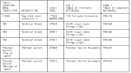
TlA3Z Tag shoe card ITOU3 1/0 Tai Igate Connector FRUl70 connector z WA005/006
TBI Terminal block ZTOIO CU-Al Logic Gate (hinge side)
FRUl60
TB2 Terminal block ZTOII CU-Al Logic Gate FRUl60 (hinge side)
TB3 Terminal block ZTOII CU-Al Logic Gate FRUl60 (hinge side)
Thermal Thermal switch ZT020 Thermal Switch Assembly FRU224 Switch
(Top of gate)
Thermal Thermal swi tch YFOl5 Thermal Switch Assembly FRUl43 Switch
(Bottom of gate)
[image:15.1224.67.517.106.356.2]Legend
Tape Unit and Drive Location Area Definitions
LOGIC LOCATION AREA IDENTIFIER Al CBl Compressor
DC Switch
-PI
OK
-Cartridge Latched Sensor and LED
-Cartridge Present Sensor and LED
-File Reel Tach
-FPSW
-J14
-Machine Reel Tach Phase A Sensor and LED
-Machine Reel Phase B Sensor and LED
-PI
3480 MI
DESCRIPTION
Logic board in each drive in the tape unit
Circuit breaker (primary power)
Compressor
DC swi tch (these are addi-tional contacts on the drive fan and power switch)
Plug
Deck assembly
Cartridge latched sensor and LED
Cartridge present sensor and LED
File reel tach-ometer
Deck assembly file protect switch
Connector for tension transducer
Machine reel tachometer phase A sensor and LED
Machine reel tachometer phase B sensor and LED
Connector for tape path sensor A
EC336395
<C Copyright IBM Corp. 19B4. 19B5
LOGIC PAGE
LOC 1
TABLE OF CONTENTS REFERENCE
AAOOO 02A-Al Logic Board Pin AA100 and Card Side
YF050 Tape Unit AC Power CB YF060
YF050 Major FRU Locations YF060 50/60 Hz
SNOOl/002 Tape Unit Locations (Sheet 2)
SNOOl/002 (Sheet 2)
SNOOl/002 (Sheet 1)
SNOOI/002 (Sheet 1)
SNOOI/002 (Sheet 2)
SNOOI/002 (Sheet 2)
PAOOO/OOI (Sheet 2)
SNOOI/002 (Sheet 1)
SN001/00l (Sheet 1)
Drive Locations
Cartridge Latch Assembly
Cartridge Present Sensor
File Reel Motor
File Protect Switch
Tension Transducer
Machine Reel Tach Sensor A
Machine Reel Tach Sensor B
SNOOl/002 Tape Path Sensor A (Sheet 1)
CARR 1
TABLE OF CONTENTS REFERENCE FRU058 FRU218 FRU030 FRU104 FRU104 FRUOll FRU010 FRU003 FRU009 FRU014 FRU225 FRU226 FRU006
)
LOGIC LOCATION AREA IDENTIFIER -P2 -P3 -p4 -P5 -P6 -P7 -Plenum Press Sw-Tape Path Sensor A and LED
-Tape Path Sensor B And LED
-Tray Solenoid
Drive Fan and Power Sw itch DSP -Jl -J2 -J3 -J4 -Ready Swi tch DESCRIPTION
Connector for tape path sensor B
Connector for cartridge present sensor and f i Ie protect swi tch
Connector for cartridge latch-ed sensor
Connector for machine reel tach phase B sensor
Connector for machine reel tach phase A sensor
Connector for fi Ie reel tach
Plenum pressure sensor swi tch
Tape path sensor A and LED
Tape path sensor B and LEO
Cartridge latch solenoid
Orive fan and power switch
Message display
Connector
Connector
Connector
Connector
Switch
LOC 1
LOGIC TABLE OF CONTENTS PAGE REFERENCE
SNOOl/002 Tape Path Sensor B (Sheet 1)
SNOOI/002 (Sheet 1
and 2)
SNOOl/002 (Sheet 1)
SNOOI/002 (Sheet 1)
SNOOl/002 (Sheet 1)
Cartridge Present Sensor and File Protect Swi tch
Cartridge Latch Assembly
Machine Reel Tach Sensor B
Machine Reel Tach Sensor A
SNOOl/002 Fi Ie Reel Motor (Sheet 2)
SNOOl/002 (Sheet 2)
SNOOl/002 (Sheet 1)
SNOOI/002 (Sheet 1)
YG010 YG 110 YF020 WOOOO WOOOI WOOOO WOOOI WOOOO WOOOI WOOOO WOOOI WOOOO WOOOI
)
Plenum Assembly and Pressure Switch
Tape Path Sensor A
Tape Path Sensor B
Latch Sensor
Tape Unit Locations
Operator Control and Display
Ready/Not Ready Switch
)
Legend
CARR 1
TABLE OF CONTENTS REFERENCE FRU007 FRU010 FRUOll FRU226 FRU225 FRU003 FRuo40 FRUo06 FRU007 FRU002 FRU104 FRU021 FRU109
Legend
~)
lGND 35
o
Legend
Tape Unit and Drive Location Area Definitions (Continued)
LOGIC
LOCATION LOC I
AREA LOGIC TABLE OF CONTENTS
IDENTIFIER DESCRIPTION PAGE REFERENCE
-Rewind Switch WDOOO Rewind Sw itch
Switch WDOOI
-Unload Switch WDOOO Unload Swi tch
Swi tch WDOOI
EL External load WDOOO Major FRU Locations register panel WDOOI 50/60 Hz (-5 V dc
Re-sister panel)
Fan Fan (located near YF050 Major FRU Locations the compressor in YF060 50/60 Hz
the tape unit for 50 Hz)(fan is lo-cated at the bot-tom of the tape unit frame for 60 Hz)
Fan Fan for drive YGOIO 50/60 Hz Blower gate (drive 0) Assembly
YG 110 (drive 1)
Fi Ie Reel Fi Ie reel motor YGOIO F i Ie Ree 1 Motor
Motor (drive 0)
YG 110 (drive 1)
Head (Tape Solenoid at the YGOIO Tape Lifter Solenoid Li fter) head to move tape (drive 0)
Solenoid away from the YG 110 head during high- (drive 1) speed tape
move-ment (tape lift-er)
Local Local read/write VPOOI Read Adapter Cables and and control DDB WOIO Write Adapter Cables cab 1 i ng W020
CU/TU ZWIOI
CUO local drive ZW102 address 0-7 ZW103 CUI local drive
address 8-F
Machine Machine reel YGOIO Machine Reel Motor Reel Motor motor (drive 0)
YG 110 (drive 1)
On 1 i ne/ On 1 i ne/off 1 i ne SNOOI/002 Tape Unit Locations Offline swi tch (Sheet 2)
Switch
3480 MI EC336395
~ COPV"9ht IBM COfp. 19B4. 1985
o
CARR I
TABLE OF CONTENTS REFERENCE FRUl09 FRUl09 FRU036 FRU071 FRU020 FRU003 FRU216 FRU087-089 FRU091-093 FRU004 FRUI05
o
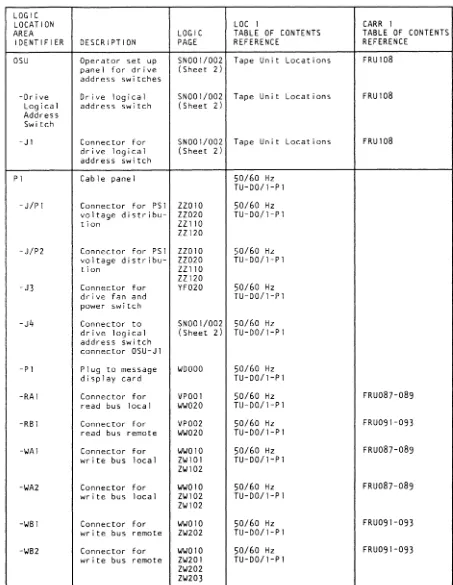
LOGIC LOCATION AREA IDENTIFIER OSU -Drive Logical Address Switch -Jl PI -J/Pl -J/P2 -J3 -J4 -PI -RAI -RBI -WAI -WA2 -WBI -WB2 DESCRIPTIONOperator set up panel for drive address switches
Drive logical address switch
Connector for drive logical address switch
Cable panel
Connector for PSI voltage distribu-tion
Connector for PSI voltage distribu-tion
Connector for drive fan and power switch
Connector to drive logical address switch connector OSU-JI
Plug to message display card
o
LOGIC PAGE
o
LOC I
TABLE OF CONTENTS REFERENCE
SNOOI/002 Tape Unit Locations (Sheet 2)
SNOOI/002 Tape Unit Locations (Sheet 2)
SNOOI/002 Tape Unit Locations (Sheet 2)
50/60 Hz TU-DO/I-Pl
ZZ010 50/60 Hz ZZ020 TU-DO/l-Pl ZZl10
ZZ120
ZZ010 50/60 Hz ZZ020 TU-DO/l-Pl ZZ 110
ZZ120
YF020 50/60 Hz TU-DO/l-Pl
SNOOI/002 50/60 Hz (Sheet 2) TU-DO/l-Pl
WDOOO 50/60 Hz TU-DO/l-Pl
Connector for VPOOI 50/60 Hz TU-DO/l-Pl read bus local WW020
Connector for VP002 read bus remote WW020
Connector for WOIO write bus local ZW10l ZW102
Connector for W010 write bus local ZW102 ZW102
Connector for WOIO write bus remote ZW202
Connector for WW010 write bus remote ZW201 ZW202 ZW203
50/60 Hz TU-DO/l-Pl
50/60 Hz TU-DO/l-Pl
50/60 Hz TU-DO/I-Pl
50/60 Hz TU-DO/l-PI
50/60 Hz TU-DO/l-PI
o
Legend
CARR I
TABLE OF CONTENTS REFERENCE FRUI08 FRU108 FRU108 FRU087-089 FRU091-093 FRU087-089 FRu087-089 FRU091-093 FRU091-093
Legend
o
lGND 40
[image:17.1229.626.1079.83.668.2]Legend
Tape Unit and Drive location Area Definitions (Continued)
LOGIC LOCATION AREA IDENTIFIER P2 -JI -AI -BI -WAI -WBI PA -JI
-J2, J3
-J4-J8, Jll
PASW
Power On Reset Switch PS PSI PS-Ol -CBI
3480 MI
DESCRIPTION
Read/write DDB cable connector panel between tape units
LOGIC PAGE
LOC 1
TABLE OF CONTENTS REFERENCE
TU-P2 Read/Write Bus Connectors
CARR I
TABLE OF CONTENTS REFERENCE
FRUI99, 248, 264, 265
Thermal connector SN001/002 Tape Unit Locations (Sheet 2)
Connector for read bus local
Connector for read bus remote
Connector for write bus local
Connector for write bus remote
Power amplifier
Connector
Connectors
Connectors
Physical address switch
Power on reset swi tch
Tape unit power supply I
Tape unit power supply 1
Tape unit power supply I
Circuit breaker
EC336395 WW020 WW020 WWOIO ZWI03 WW010 ZW203 PAOOO/OOI PAOOO/OOI (Sheet 1)
PAOOO/OOI (Sheet 2)
PAOOO/OOI (Sheet 3)
TU-P2 Read/Write Bus Connectors
TU-P2 Read/Write Bus Connectors
TU-P2 Read/Write Bus Connectors
TU-P2 Read/Write Bus Connectors
TU-DO/I-PA Power Amplifier Board
TU-DO/l-PA Power Amplifier Board
TU-DO/l-PA Power Amplifier Board
TU-DO/I-PA Power Amplifier Board
FRU087-089
FRU087-089
FRu087-089
FRU087-089
FRU059
SN001/002 Physical Address Switch FRUI29 (Sheet I)
SNOOI/002 Tape Unit Locations FRU107 (Sheet 2)
YFIOO Tape Unit DC Power FRU095 Supply
(two different types)
YFIOO Tape Unit DC Power FRU095 Supply
(two different types)
YF100 Tape Unit DC Power FRU095 Supply
(two different types)
YF100 Tape Unit DC Power FRU095 Supply
(two different types)
~ Copyright IBM Corp. 19B4. 19B5
J \ ,
)
LOGIC LOCATION AREA IDENTIFIER -CB2 -Fl-FI3
-P/Jl to p/J16
Remote
Tape Lifter Solenoid (Head) TBI Tension Transducer Assembly Terminator (See note I
on WW020)
Thermal Switch
Thermal Swi tch S-2
Thread Motor
1 )
legend
LGND 45
LOC 1 CARR 1
LOGIC TABLE OF CONTENTS TABLE OF CONTENTS
DESCRIPTION PAGE REFERENCE REFERENCE
Circuit breaker YF100 Tape Unit DC Power FRU095 Supply
(two different types)
Fuses YF100 Tape Unit DC Power FRU095 Supply
(two different types)
Connectors YF100 Tape Unit DC Power FRU095 Supply
(two different types)
Remote read, VP002 Read Adapter Cables FRU087-089 wr i te, and WW010 and Write Adapter FRU091-093 control DDB WW020 Cables
cables ZW201
CU/TU ZW202
CUO remote drive ZW203 address 8-F
CUI remote drive address 0-7
Solenoid at the YG010 Tape Lifter Solenoid FRU216 head to move tape YG 110
away from the head during high-speed tape move-ment (tape lift-er)
Terminal block YF050 TBI FRU075, 076
YF060
Tension trans- ZT030 Tension Transducer FRU014 ducer assembly
Wr i te bus termin- WWOIO TU-P2 Read/Write Bus FRUI99, 248, 264,
ator Connectors 265
Thermal switch in SNOOI/002 Thermal Sw itch FRU 110 DO/I logic gates (Sheet 2) Assembly
Thermal switch SNOOI/002
(Sheet 2) Tape Unit Locations
FRU082
Thread motor YGOIO Threader Motor FRUOOI (drive 0)
YG 110 (drive 1 )
legend
LGND 45
,
)
o
o
Legend
Tape Unit and Drive Location Area Definitions
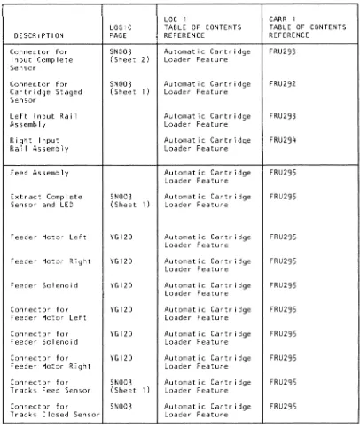
Automatic Cartridge Loaders
DESCRIPTION Load Assembly Cartridge L~tched Sensor and LED
Cartridge Present Sensor and LED
Feed Complete Sensor (Hall Effect Switch) Load Assembly Fi Ie Protect Switch
Connector for Cartridge Present Sensor
Connector for File Protect Sw itch
Connector for Load Motor Complete Sensor
Connector for Cartridge Latched Connector for Feed Complete Sensor Load Motor Load Motor Complete Sensor And LED
Load Motor
3480 MI EC336395
-~ Copynqhf !BM Corp 1984. 1985, 1986
LOGIC PAGE
SNOOI/OOZ (Sheet 1 )
SNOOI/OOZ (Sheet 1 )
SN003 (Shee t 1) SN001/00Z (Sheet Z) SN001/00Z (Sheet 1) SN001/00Z (Sheet 2) SN003 (Sheet 2) SN001/002 (Sheet 1) SN003 (Sheet 1) YG120 SN003 (Sheet 2)
YGI20
LOC 1
TABLE OF CONTENTS REFERENCE
Load Locations Cartridge Latch Assembly
Cartridge Present Sensor
Automatic Cartridge Loader Feature Fi Ie Protect Switch
Cartridge Present Sensor
File Protect Swi tch
Automatic Cartridge Loader Feature Cartridge Latch Assembly
Automatic Cartridge Loader Feature Automatic Cartridge Loader Feature Automatic Cartridge Loader Feature
Automatic Cartridge Loader Feature
CARR I
TABLE OF CONTENTS REFERENCE
FRUO II
FRU010 FRU28z FRU009 FRUOIO FRU009 FRU284
FRUO II
FRU282 FRU283 FRU284 FRU283
c
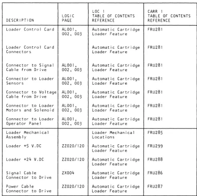
DESCRIPTIONLoader Control Card
Loader Control Card Connectors
Connector to Signal Cable from Drive Connector to Loader Sensors
Connector to Voltage Cable from Drive Connector to Loader Motors and Solenoid Connector to Loader Operator Panel Loader Mechanical Assembly
Loader +5 V.DC Loader +24 V.DC Signal Cable Connector to Drive Power Cable
Connector to Drive
LOGIC PAGE ALOO I, OOZ, 003
ALOO I, 002, 003 AL001, 002, 003 ALOO I, 002, 003 ALOO 1, 002, 003 AL001, 002, 003
ZZOZO/120 ZZOZO/120 ZX004 ZZ020/1Z0
Q
LOC 1
TABLE OF CONTENTS REFERENCE
c
Automatic Cartridge Loader Feature Automatic Cartridge Loader Feature Automatic Cartridge Loader Feature Automatic Cartridge Loader Feature Automatic Cartridge Loader Feature Automatic Cartridge Loader Feature Automatic Cartridge Loader Feature Loader Mechanical Locations
Automatic Cartridge Loader Feature Automatic Cartridge Loader Feature Automatic Cartridge Loader Feature Automatic Cartridge Loader Feature
CARR I
TABLE OF CONTENTS REFERENCE FRuz81 FRU281 FRU281 FRU281 FRUz81 FRU281 FRUz8l FRU285 FRU299 FRUZ88 FRUz86 FRU287
c
o
LGND 46
[image:19.1230.625.1026.103.501.2] [image:19.1230.70.469.130.630.2]Legend
Tape Unit and Drive Location Area Definitions
Automatic Cartridge Loaders
DESCRIPTION Loader Operator Panel-Attention and Power LED, Mode and Start Switches Loader Operator Panel
Attention LED on Operator Panel Power LED on Operator Panel Start Switch on Operator Panel
Input Stack Assembly
Cartridge in Stick Sensor and LED
Cartridge Staged Sensor and LED
Input Complete Sensor and LED
Input Motor Connector for Cartridge in Stack Sensor
Connector for Input Motor
3480 MI EC336395
© CopyrIght IBM Corp. 19B4. 1985. 1986
LOGIC PAGE AL002 AL002 AL002 AL002 AL002 SN003 (Sheet 2)
SN003 (Sheet 1)
SN003 (Sheet 2)
YGl20 SN003 (Sheet 2)
YG120
LOC 1
TABLE OF CONTENTS REFERENCE
Automatic Cartridge Loader Feature
Automatic Cartridge Loader Feature Automatic Cartridge Loader Feature Automatic Cartridge Loader Feature Automatic Cartridge Loader Feature Automatic Cartridge Loader Feature Automatic Cartridge Loader Feature
Automatic Cartridg Loader Feature
Automatic Cartridge Loader Feature
Automatic Cartridge Loader Feature Automatic Cartridge Loader Feature Automatic Cartridge Loader Feature
CARR 1
TABLE OF CONTENTS REFERENCE FRU298 FRU298 FRU298 FRU298 FRU298 FRU290 FRU291 FRU292 FRU293 FRU290 FRU291 FRU290
}
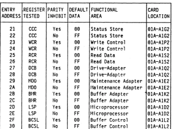
DESCRIPTION Connector forInput Complete Sensor
Connector for Cartridge Staged Sensor
Left Input Ra i I Assembly
Right Input Ra i I Assembly Feed Assembly Extract Complete Sensor and LED
Feeder Motor Left Feeder Motor Right Feeder Solenoid Connector for Feeder Motor Left Connector for Feeder Solenoid Connector for Feeder Motor Right Connector for Tracks Feed Sensor Connector for
Tracks Closed Sensor
)
Legend
LGND 47
LOC I CARR I
LOGIC TABLE OF CONTENTS TABLE OF CONTENTS
PAGE REFERENCE REFERENCE
SNOO3 Automatic Cartridge FRU293 (Sheet 2 ) Loader Feature
SNOO3 Automatic Cartridge FRU292 (Sheet 1 ) Loader Feature
Automatic Cartridge FRU293 Loader Feature
Automatic Cartridge FRU294 Loader Feature
Automatic Cartridge FRU295 Loader Feature
SNOO3 Automatic Cartridge FRU295 (Sheet 1 ) Loader Feature
YGl20 Automatic Cartridge FRU295 Loader Feature
YG120 Automatic Cartridge FRU295 Loader Feature
YGl20 Automatic Cartridge FRU295 Loader Feature
YGl20 Automatic Cartridge FRU295 Loader Feature
YG120 Automatic Cartridge FRU295 Loader Feature
YGl20 Automatic Cartridge FRU295 Loader Feature
SNOO3 Automatic Cartridge FRU295 (Sheet 1 ) Loader Feature
SNOO3 Automatic Cartridge FRU295 Loader Feature
Legend
LGND 47
[image:20.1227.626.1027.67.554.2] [image:20.1227.622.1028.72.555.2]o
o
o
o
o
o
o
o
l-egem~ I-egend
LGND 48
Tape Unit and Drive Location Area Definitions
Automatic Cartridge Loaders
, - - -
r---I- .. _ .... _---LOC 1 CARR 1
LOGIC TABLE OF CONTENTS TABLE OF CONTENTS DESCRIPTION PAGE REFERENCE REFERENCE
Connector for SNOO3 Automatic Cartridge FRU295 Extract Complete (Sheet 1) Loader Feature
Sensor
Trad Closed SNOO3 Automatic Cartridge FRU295 Sensor and LED (Sheet 1) Loader Feature
Track Feed Sensor SNOO3 Automatic Cartridge FRU295 and LED (Sheet 1) Loader Feature
---.----Output Stack Automatic Cartridge FRU297 Assembly Loader Feature
Output Motor YG120 Automatic Cartridge FRU297 Loader Feature
Connector for YG120 Automatic Cartridge FRU297 Output Motor Loader Feature
-Stack Up Position SNOO3 Automatic Cartridge FRU296 Sensor and LED (Sheet 1) Loader Feature
Connector for SNOO3 Automatic Cartridge FRU296 Stack Up Position (Sheet 1) Loader Feature
Sensor
-Stack Low Position SNOO3 Automatic Cartridge FRU89 Sensor and LED (Sheet 1) Loader Feature
Connector for SNOO3 Automatic Cartridge FRU289 Stack Low Position (Sheet 1) Loader Feature
Sensor
Legend
LGND 48
Notes
NotesLGND 50
IOMI EC336396 Notes
LGND 50
)pynght IUM Corp. 1984. 1985. 1986. 1987
o
o
o
Legend
Error Analysis Diagram (EAD) Logic Blocks
EADs are block diagrams which show the logical functions relating to the error code.
The error analysis logic blocks contain the following information:
•
Physical card locationII
•
Card nameEJ
•
Test pointsII
•
FRU numberII
•
Logic diagram1:1
Note: The actual logic diagram references must be used when performing scoping or probing procedures.
• Signal lines and buses that pertain to the error condition
II
OIA-AIC2
Digital Servo Card
message display load cmd ----.
- load message display pIa ----.
msg disp bus parity error _____
- reg data bus repowered ______ ~
3480 MI EC336395
~ Copynght '8M Corp 1 q84 1 ga5
OIA-AIY2
WDOOO
o
o
o
o
o
o
Legend
LGND 55
Legend
Logic Diagrams
Logic diagrams show the input and output connectors of each card.
Card Location Chart
Card Location Charts for each board are included at the start of the logic diagrams. The charts identify the cards and cables that plug into the board, their names, and the location of plug information and reference pages (input and output connector logic diagrams). Crossover connectors and their part numbers are also shown.
Card Plug List
Card Plug Lists
EJ
are provided for each card in the subsystem. They containinformation such as the card function, location, and logic diagram page numbers. Part, EC, and REA numbers for the primary and alternate cards are also listed. The comments area provides information about an alternate card.
For example, an EAD indicates that inputs and outputs from the Write Data Flow card 01 A-A 1 P2 had to be scoped. The 'P' card position
II
on the chart shows that the card input and output connectors can be found on logic pages DFOO 1 and DF002EJ.
This information can also be found on the Card Plug List.To expand on the example, suppose the EAD also indicates that the card output to be scoped was the MUX WRITE DATA and the inputs were the BF/WD CLOCK S2-S3 and WDF DATA.
The "Sample Logic Diagrams" on LGND 15 show that the 'MUX WRITE DAT' line
II
is found on logic page DF00211) and that it can be scoped at the Top Card Connector pins (identified by TceD following the card label). The inputs ('BF/WD CLOCK' lineIlJ
and 'WDF DATA' line llTare found on logic page DFOQlJD and can be scoped at the Bottom Card Connector pins (BCC) on the same cardm
andm.
The connector is identified by the (BCC)II
following the card label.Note: BCC pins are the same as the pins on the back of the board.
Multiple Logic Diagrams for One Card
Logic pages are not true functional representations of logic cards. They only represent the input and output connectors to the cards.
A card can have three types of connectors:
• Bottom Card Connector (BCC)
• Middle Card Connector (MCC)
• Top Card Connector (TCC)
Only one type of connecter is shown on each logic diagram; therefore, one card may be shown on up to three separate diagrams. To determine the number of logic diagrams for a card, see the card plug list.
Note: The relationship between the input and output card connector pins cannot be determined from the logic diagrams. When required, these relationships are defined in the Error Analysis Diagram (EAD) section by error code.
3480 MI EC336395
~ Copyright IBM Corp. 1984. 1985
J
}
"
N
)
,.
)
Card Location Chart
5
5
CMlLE - IRITE BUS (Lo) CABlE - llIHE BUS (HlJ REFER TO LOGIC PAGE(S) - ITB81 REFER TO LOGIC PAGUS) - ITli3
liP
CARD -WRITE CONTRIlI. PUJi
INFO-AA1i3 lIEF.
PAGE-A
Dflll ••• 2EJ
o
R
5
T
U
CARD - CARD - CARD - CARD -DEVICE READ m READ.[LK. REGULATOR INTERFACE AND FOlIIiAT
PlUG INFO- PlUG INFO- PlUG INFO- PlUG
INFO-AA114 AA11S AAllG AA117 REF. REF. REF. REF. PAGE-01111.112 £C •• 101112 RCIII108112 RGI.l
I
:5£E NOTE:
: (3) :
...
... .
... .
i~OYER····:
PN-6819m:
::::::::::::
...
II • • • • • • • • • • •~i~O;Ei"··:
P11-6819l11:
... .
... .
\
)
NOTE
-sorm
IS UNUSED O\J£TO REGULATOR [ARO 5IZf
~
)
v
CABLE -LOCAl PIJIT
lIEF. PAb[-IU.S/JIG
y
2
3
}
Legend
LGND 60
E1
Card Plug ListrD~---.
I 1
FUNCTION - C""IIINEL QDQPTER
LOCQTION - 1 <H12C2
LOGIC SHEETS - CAO<)1. Cf100Z
I
1---~I--P-RI-~-R-y---~I--~-T-ER-~-T-E---I
PNAl'IE'I
:~:~~:R
REQ NUl'IBER
KUCf1
6050663
9i1682f1
1---
I COl'lI'lENTS-' 3 0 E - < l I f 1 . f 1 - - - COl'lI'lENTS-'Legend
LGND 60
G
c
o
Legend
Logic Diagrams (Continued)
Sample Logic Diagrams
.,-p"8Qpon - J(~ QDnA£U I!U~
(P.~I..-oo,
~x_oo _
I'IPOO, kR "DOAUS ['(TEND BIT 0
.... px_o, _ XII ADOAESS E'TEND BIT ,
"'001
~X'--OOO - lIR lDAD
CSOO1
_xAACOO -
,",,00,
lIR AfAO ;ATE _ X _ _,",00, lIR ~ITE ;Are ..,OIAGOO - OI~TIC IIODE
"'00'
~ItRSOO
-"'00,
0tE CK RESET-~soo - _DwARE REst:T
IIPOO1 WCOO4
ICSII~Clt04 - IF two ClOCk S2-S3
CSOO1
Ii
m
",l1F,..s - WOF DQTA ~7.P
(I' .0-71 BAOO1
IWIlI'ENO
!!AOO'
-"OF
Eoro &OIC""IOO - ;AI'DIOO' IN "'DI'TOC
·.,DF
TIlCCLE!!ADO'
... CS><TL... - SHOAT L.~ .... ITE TO R[AO ReDO' .,110Z
O""'ENT ourJCCTcnS SS
,,,
- VOL. TACE PINS • • IP2B" 2 +1 .71/ 111. S1' D00511 A-Q, /1'28"
3 .1)",.\11.7
•
+,v DOl, J03. P03. U03 .1)2c",
CND D08. .JOI. poe. U08 000" .. A-A, ,plS"I> CND I0I01>. 1111" W2" 11129 .pv.1I1.7 7 CNO leoe-. X" • a •• W29
'1'2""
D e ;ND Y06. "11 , Y2." Y29 00071\A-A,
'''"1'' F I 9 eND 106· Z11. 12', 129.1=".1.",
.7 0 I '''2511 0 I 11);)0811 A-Q1/P581',
I .pv .... , .1I
000, I I
3480 MI EC336396
o
•• m CARO fICC)
II
r:~
~IOI"OUII>.
All :l~~~m~
-s
o 1111'1Ol/"'''
:m::g;~~z AO, :a%~m:&
0(.,Il107/... "14/1'07(":&
'(PI"'08/~ ""/1'09'"
( "'611>'0161;
Il109/_ "'711'" (71 I .. 'B/P12(PI I'I'O/A7'>.
I
I 002/'" 3_ "1
ClUBb. I
I Oo2l1J' 3- S
1't'2/1'~ I
I c.zz/", ~ S
C' l/12o.
I
I
C10/1~ c:..J/CO •• S
I
I
C09/_ I ;08/82>-I D,l/Blob.~IOle03/DI ~~~~~~~~~
~I' 1004/01
l'
131D05ID3 21 80./ 02 1 ~~~~gm~::& ('180'/001 SO/U0513AI-o &(51 DOb/D51 ~~~l~~::&(61 807/0.
0(7ID07ID7 '''5081.BI-o '( PI808/DeI
I
'8ro07l5A 1-0 I 59/S09(58I-o.J06/D<h :~~n~~r.:
I
I 62/U,0(7AI-o J07/B>.
:~~~m~g::&
I
J02IE, .. 65/S'3(88);
I f>61U, 2 (9A) 8,2IFCb. 671u,3(9BI ... e/J09jJ
fb9/J'~
~7/.J"
I
I
Ir,/J'lj
18/J05. I 1 ~ I!811COZ- i
I
rO'01F
9/UO'-'I
[8'0/F' "58_D~9'/D'jI
, ,
CONTROl. ~tT - A' 80RAD .... ITE DATA Fl(lJ
m
SHEET _.7'6263 Ec-33l274 L O C a , - p z m
USN ooolf> pRI-22DEC82 0733 0
I
,
QUCo SEC 0
I~OR""KSE!I N(xTBLk DC
loo!,
IItQCH-SQCLJ
/CID .SCAJ JOB KSCRur.Jl
o
o
D
}.
"0 CARO (TCCI • OWD
101Y02/1 A8 2/Y22(01-(1)Y03/8'
l~211Y23C11
•o 12lY05/121 1221Y25121,
~(3IY07l8J1
23/Y2713Ij~ I' I Y08180 2'/Y28 (" 1"1Y10/15 2S/YJO(51
T I I
t(6IY1Z1861 26/Y32(6Ij L171Y33/871 Z7lY1](7I
I
32/1012'
33/10127 3'/10128
35/10130
o
o
Legend
.110"01_· .... 0>-_______________ - - -+ I'llx IoIAITE DATA ---l&"'''DDATAOO
:1~m:~::& (0-9101002
D f 0 0 Z 000'
I
,
'3/Z121]I-o
"
.1123141:&
:~mm:-o • 7IZJO ( 71-0
::mm::t
I
51Z0Z_~5~o-J5'/Z32 ••
---~---s
S
DI002 + DATA ClOC. ---SIoIDDVCItOO 01002 + DHIVE ClUCK SIoIODICItOO
ccwrROl. ~lT - A' IOQRD .... ITE DATA FL.OW
D
SHEET _47'6264 EC-llJ274 LOC-'_ P2
1m
USN 00031> PAI-22DECe2 073l D
I AlOC- SEC
I
F 0 IPFUR .... SEB N[XTBLK DE I 0I
fItQC,... SACt II
2 CIO ItSCAD ..De I( St;A.IPlJlI 1000'
Legend
o
LGND 65
Legend
Logic Diagrams (Continued)
Bundled Lines
Bundled lines combine Ihe billines in a bus and represenl the bus as a single line. The bit lines in the bundle are identified by a 'short-hand' notation. The (P,O-7)
D
Indicates that a parity bit and bits 0 through 7 are included In the REMOTE CU ADDRESS BUS. An asterisk (")D
following the 'short-hand' notation (P,O-l) indicates that the bit lines are defined in the information area0
at the bottom of the logic diagram.The PINS columns
D
in the information area define the pins for each bundle on the diagram. Pins 10/J13 through 1B/P04 represent the pins contained in the REMOTE CU ADDRESS BUS bundleD·
The parity bit Is on pin 10/J13 (low order zeros do not appear on the diagram for logical pins0
andII)
and the 7 bit is on pin 1B/P04.Logical/Physical Pins
Pins are identified by logical pin notation and pin number
D.
J02 is the physical pin. The 34 is a logical pin notation and is used for engineering purposes only. Low order zeros are not used for logical pin notation. For example, logical pin 10=
1, 20= 2
0
andII,
and so on.3480 MI EC336396
': COpyrlghllS". Corp 1984. 1985. '986. '987
Legend
LGND 70
fJ
D
'"
CARD C ICC! /- - -
~
- - ... RUUTE CUADDRES~
illS - - -... R"'ADROO:;;~: : : : : : : : : T - E D - - - P ' l o 4 > " : : : - 'CP.«>-71., ... - - - CP.o-71,,",OO]
...001 P'lZlAZ "
-_'510000 ... AEI'Ol[ CU SEND
EJ
... 001 P'I lJ'1Il
~~OO + AlEI'Ol( CU lie_EDGE
IPSPORSOO - I>QWER ()OI RESET
---uo.,..
~~C~O~O( IIPOO,
, ---U05l1'
s
'" I
o I
~
I
0110' IThe follo ... ing pin I i.1 .ho .... ho ... the '.hort-hand' bundle
notation relate~ to
the PINS column •.
10 J13 • P bit
11 G 10 • 0 b t
12 G12 • 1 b t
13 G 1] • 2 b t
14 M02 • 3 b t 15 MO] • It b I
16 M04 • 5 b I
17 P02 • 6 b I
18 P04 • 7 b I
'I
- - - + AE"UTC tu DATA IlUS - - - t s .... UuSoo
'~D
".<-,,~~
~
""'001 ... LOCAL CO ....~TE"
---tILCLI'ISTOO]'11>05, •• - - - - WKOO1 ... LOCAL CU CONNECTED ILCLC:OOOOO
1211>09. "'00' ... L~ CU SEND .LCLSNOOO
]111>07. ,,",00, + ~ CU QCJ(N~EDcE ILCLAO<OO
]./.J02tI ",00] ... I'E~ .... llE ~I