N A N O E X P R E S S
Open Access
Fast Swept-Wavelength, Low
Threshold-Current, Continuous-Wave External Cavity
Quantum Cascade Laser
Xuefeng Jia
1,2, Lijun Wang
1,2*, Zhiwei Jia
1,2, Ning Zhuo
1, Jinchuan Zhang
1, Shenqiang Zhai
1, Junqi Liu
1,2,
Shuman Liu
1,2, Fengqi Liu
1,2*and Zhanguo Wang
1,2Abstract
We present a low threshold-current and fast wavelength-tuning external cavity quantum cascade laser (EC-QCL) using a scanning galvanometer in the Littman-Metcalf cavity geometry. The EC-QCL could repeatedly swept at 100 Hz over its full tuning range of about 290 nm (2105 cm−1to 2240 cm−1), providing a scan rate of 59.3μm s−1. The continuous-wave (CW) threshold current of the EC-QCL was as low as 250 mA and the maximum output power was 20.8 mW at 400 mA for a 3-mm-long QCL gain chip. With a sawtooth wave modulation, a scan resolution of < 0.2 cm−1 can be achieved within the tuning range. The low power-consumption and fast swept-wavelength EC-QCL will be beneficial to many applications.
Keywords: Quantum cascade laser, External cavity, Fast swept-wavelength
Background
The mid-infrared (MIR) region of the electromagnetic spectrum is the molecular fingerprint region, since fundamental ro-vibrational transition energies of most molecules lie in this spectral region. Laser absorption spectroscopy in the MIR region is important for a diverse number of applications such as medical breath analysis, atmospheric pollutants sensing, and indus-trial effluents monitoring [1–3]. Particularly, with the fast development of MIR lasers, the performance of optical instruments based on spectroscopy method has been greatly improved to provide rapid, sensitive, and accurate measurements.
For the laser absorption spectroscopy, a tunable single-frequency laser with narrow linewidth and modest power is required. Distributed feedback (DFB) quantum cascade lasers (QCLs) [1] are suitable light sources for these appli-cations because of their very narrow linewidth [4], high output power, and room-temperature continuous-wave (CW) operation. However, a single DFB laser has a very
limited tuning range of a few cm−1(~ 10 cm−1) via slow temperature tuning, which limits its usefulness for broadband absorption features and multi-species gas detection [5]. DFB arrays have achieved an impressive tunability over 220 cm−1. However, DFB arrays need electron beam lithography to fabricate different grat-ing periods, which is complex and expensive. More-over, DFB arrays need beam combining of different wavelengths for sensing applications [6, 7].
External cavity quantum cascade lasers (EC-QCLs) are widely used as reliable, broadly tunable light sources, which can provide a tuning range greater than 300 cm−1 [8] with slow scan by stepper motor. For traditional EC-QCL, the mode-hop free tuning can be achieved by mode tracking system which was proposed by Wysocki et al. [9]. The laser current and the EC length are modulated with phase-matched triangular voltage ramps during the tuning process. However, this only allows mode-hop-free tuning of ~ 1 cm−1 at any wavelength inside the full tuning range of the EC-QCL [10]. A high wavelength tuning rate EC-QCL is needed for reducing the measurements time of chemical mixtures in the gas phase. Rapidly swept EC-QCLs have been designed with intra-cavity micro-eletromechanical system (MEMS) or
acousto-* Correspondence:[email protected];[email protected]
1Key Laboratory of Semiconductor Materials Science & Beijing Key Laboratory
of Low Dimensional Semiconductor Materials and Devices, Institute of Semiconductors, Chinese Academy of Sciences, Beijing 100083, China Full list of author information is available at the end of the article
optic modulator, which can sweep > 100 cm−1 on a sub-ms timescale [11]. Unfortunately, these rapidly swept EC-QCL systems have low spectral resolutions around ~ 1 cm−1, which is not sufficient for the nar-row absorption features.
Recently, a swept-wavelength EC-QCL source for mea-surements of broad absorption features was developed by M.C. Phillips et al. [12, 13]. The swept-wavelength EC-QCL can be tuned more than 100 cm−1at a sweep rate of 200 Hz with an average output power of 11 mW at the peak of the tuning curve at 50% duty cycle. How-ever, pulsed operation would introduce line-broadening due to the chirped current. In this paper, we use the scanning galvanometer in the Littman-Metcalf cavity geometry to realize a fast swept-wavelength EC-QCL with a tuning range of 135 cm−1 from 2105 to 2240 cm−1(4.46–4.75μm). The threshold current was as low as 250 mA in CW operation at room temperature. Time-resolved measurement using the step-scan Fourier transform infrared (FTIR) technique was performed for the EC-QCL repeatedly swept at 100 Hz. Laser spectrum analyzer was used to evaluate the spectral resolution. With a sawtooth wave modulation, a spectral resolution of < 0.2 cm−1can be achieved within the tuning range.
Methods
The EC system is based on the Littman-Metcalf config-uration, and consists of three main elements, the gain element, in our case the Fabry–Perot (FP) QCL chip with a collimating lens, a diffraction grating, and a scanning galvanometer, as shown in Fig. 1. The strain-compensated QCL active core comprises 30 periods with In0.67Ga0.33As/In0.36Al0.64As as quantum wells and
barriers, respectively, similar to that described in [14]. The devices were processed in a buried heterostructure configuration using metal-organic chemical vapor de-position (MOCVD) for the selective regrowth of Fe-doped InP. The FP–QCL gain chip with a ridge width of 12μm
Fig. 1Schematic of Littman-Metcalf external cavity configuration
[image:2.595.57.539.89.246.2] [image:2.595.305.539.340.674.2]and length of 3 mm was used to construct the EC-QCL. High-reflectivity (HR) coating consisting of Al2O3/Ti/Au/
Ti/Al2O3 (200/10/100/10/120 nm) and anti-reflection
(AR) coating of Al2O3/Ge (448/35 nm) were evaporated
on the rear facet and the front facet of the gain chip, re-spectively. The FP–QCL chip was mounted epilayer side down on a SiC heat sink with indium solder, wire bonded, then mounted on a holder containing a thermistor com-bined with a thermoelectric cooler (TEC) to monitor and adjust the heat sink temperature.
The Littman configuration we used consists of a collimating lens with the focal length of 6 mm, a dif-fraction grating with 210 grooves/mm, and a scanning
galvanometer (Thorlabs, GVS111). In the Littman config-uration as shown in Fig. 1, first-order light is diffracted into the scanning galvanometer then reflected back into the FP–QCL chip by the diffraction grating and the emit-ted single-mode laser light is extracemit-ted through zeroth-order reflection from the diffraction grating.
The emitted optical power and spectrum from the EC-QCL were measured with a calibrated thermopile detector and a FTIR spectrometer, respectively. All measurements were taken with the FP–QCL chip be-ing held at 25 °C under cw operation.
Results and Discussion
Figure 2a shows the measured cw spectra at different scanning galvanometer angles with the injection current of 330 mA. The emission peak shifts from 2105 to 2240 cm−1by rotating the galvanometer with the step of 0.1°. Figure 2b shows the measured output power and the side-mode-suppression-ratio (SMSR) at different scanning galvanometer angles same as that in Fig. 2a. A SMSR above 25 dB was realized in almost the whole tuning range. The average output power was about 8 mW and the output power profile was consistent with the electroluminescence spectrum. Figure 3 depicts the power-current-voltage (P-I-V) curves measured for the EC-QCL in the central region at 2180 cm−1. The threshold current of the EC-QCL was 250 mA, corresponding to a threshold current density (Jth) of 0.833 kA/cm2. The maximum cw
out-put power of 20.8 mW was obtained at 400 mA.
Fig. 3The P-I-V characteristics of the EC-QCL in the central region at 2180 cm−1
[image:3.595.58.289.88.245.2] [image:3.595.57.540.469.713.2]EC-QCL Scan Characterization
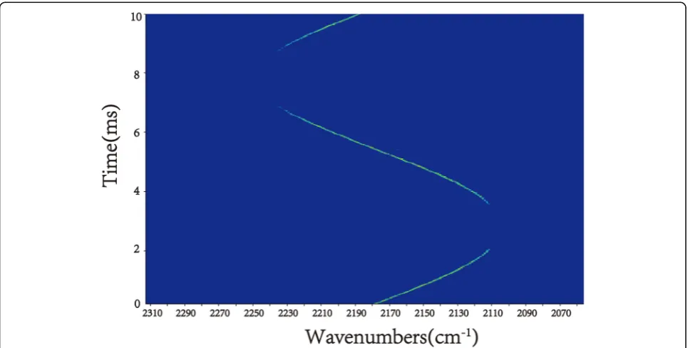
We utilized a signal generator to generate a 100 Hz sinus-oidal wave. By implementing the sinussinus-oidal wave on the scanning galvanometer, the EC-QCL wavelength can be swept repeatedly in cw mode with the current of 330 mA. The sinusoidal wave amplitude is 3 V which corresponds to the total tuning angle of 3°. For a demonstration of the EC-QCL scan characterization, time-resolved measure-ment using the step-scan FTIR technique can be applied. This technique was often used to study repeatedly oc-curred processes [15]. We make the generated signal syn-chronized with the FTIR, and the measurements were performed with a spectral resolution of 0.2 cm−1 and 20 ns time resolution. The time-resolved emission peaks were plotted in Fig.4. The EC-QCL started at 2180 cm−1 then tuning toward lower wavenumbers. After 1/4 pe-riods, the emission peak reached the minimum wavenum-ber. The wavenumber tuned from 2105 to 2240 cm−1in the next half periods. For the Littman configuration:
λ¼d=mðsinαþ sinβÞ ð1Þ
where λ is the EC-QCL wavelength, d is the grating period, m is the diffraction order, and α and β are the angles shown in Fig. 1. The first-order light is reflected to the scanning galvanometer then reflected back into the FP–QCL chip. When the scanning galvanometer ro-tates an angle ofθ, the above formula turns to:
dλ
dt¼d
cosðβþθÞ dθ
dt ð2Þ
In our configuration, m= 1, β= 7.7°,d= 4.76 μm, and the EC-QCL can operate in a fast-scan mode with the scanning galvanometer swept at 100 Hz with the rate of 12.6 rad/s, providing a wavelength tuning rate of 59.3μm s−1.
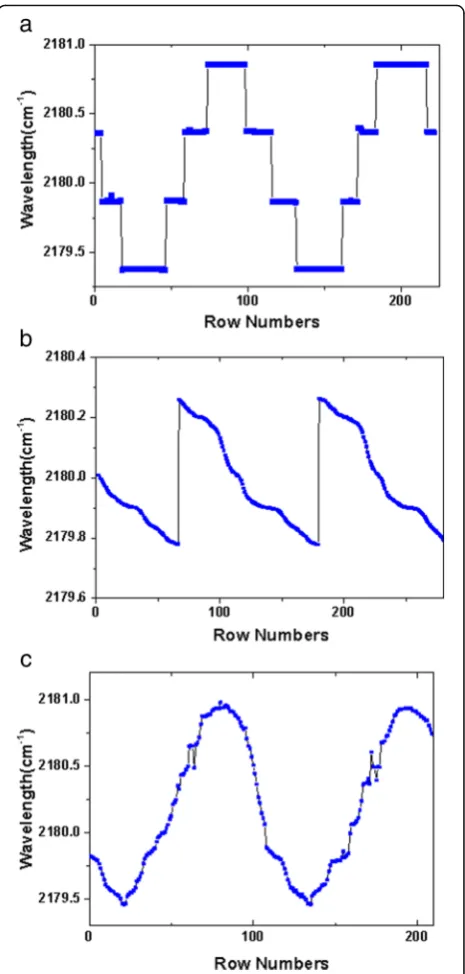
We used a laser spectrum analyzer (Bristol Model 771) to evaluate the spectral resolution. Due to the minimum re-sponse time of about 0.5 s for the laser spectrum analyzer, we reduced the galvanometer frequency to 0.02 Hz which can record the complete wavelength tuning cycle. As shown in Fig.5a, by changing the galvanometer angle, the wavelength varied discontinuously and mode hop about 0.5 cm−1could be clearly identified. The mode hop is pri-marily associated with the FP modes of the QCL chip be-cause of the non-ideal antireflection effect of the AR coating. In order to reduce mode hop spacing, we add a sawtooth wave modulation (0.02 Hz, 40 mA) to the DC driving current on the QCL chip with the galvanometer at a fixed angle. The wavelength tuning with the sawtooth wave modulation was shown in Fig.5b. In one period, the wavelength is smoothly tuned to lower wavenumbers, which can compensate for the 0.5 cm−1 mode hop.
However, it is noted that the wavelength tuning is not linear in one period, which is attributed to the temperature fluctu-ation of the QCL heat sink. The measured EC-QCL wave-length with both galvanometer tuning and sawtooth wave modulation was shown in Fig.5c. Compared to Fig.5a, the mode hop spacing has decreased to less than 0.2 cm−1.
Fig. 5aThe measured EC-QCL wavelength with the galvanometer voltage of 20 mV and the tuning frequency of 0.02 Hz. The mode hop is about 0.5 cm−1.bThe measured EC-QCL wavelength tuning with a
sawtooth wave modulation (0.02 Hz, 40 mA), which can compensate for the 0.5 cm−1mode hop.cThe measured EC-QCL wavelength with
[image:4.595.306.539.86.574.2]Conclusions
In summary, we have designed a fast swept-wavelength EC-QCL and investigated its performance, including single-mode selection, tuning range, and output power. The time-resolved step scan FTIR technique and laser spectrum analyzer were applied to measure the tuning range and spectral resolution. The EC-QCL could re-peatedly swept at 100 Hz over its full tuning range of 135 cm−1 (about 290 nm) with a scan resolution of < 0.2 cm−1, which can be achieved with a sawtooth wave modulation. The CW threshold of the EC-QCL was as low as 250 mA with a maximum power of 20.8 mW. The low power consumption and fast swept-wavelength characteristic of the device could make it a promising light source for trace gas sensing applications.
Abbreviations
AR:Anti-reflection; CW: Continuous-wave; DFB: Distributed feedback; EC-QCL: External cavity quantum cascade laser; FTIR: Fourier transform infrared spectrometer; HR: High reflectivity; MEMS: Micro-eletromechanical system; MIR: Mid-infrared; MOCVD: Metal-organic chemical vapor deposition; P-I-V: Power-current-voltage; QCLs: Quantum cascade lasers; SMSR: Side-mode-suppression-ratio; TEC: Thermoelectric cooler
Acknowledgements
The authors acknowledge the contributions of Ping Liang and Ying Hu in the device fabrication.
Funding
This work was supported by the National Key Research and Development Program (Grant No. 2017YFB0405302) and the National Natural Science Foundation of China (Grant No. 61627822).
Availability of Data and Materials
The datasets used and/or analyzed during the current study are available from the corresponding author on reasonable request.
Authors’Contributions
XFJ designed the structure, fabricated the device, performed the testing, and wrote the paper. LJW and FQL designed the structure, provided the concept, wrote the paper, and supervised the project. ZWJ, JCZ, SML, and JQL supervised the testing. NZ and SQZ completed the MBE growth. ZGW supervised the project. All authors read and approved the final manuscript.
Competing Interests
The authors declare that they have no competing interests.
Publisher’s Note
Springer Nature remains neutral with regard to jurisdictional claims in published maps and institutional affiliations.
Author details
1
Key Laboratory of Semiconductor Materials Science & Beijing Key Laboratory of Low Dimensional Semiconductor Materials and Devices, Institute of Semiconductors, Chinese Academy of Sciences, Beijing 100083, China. 2Center of Materials Science and Optoelectronics Engineering, University of
Chinese Academy of Sciences, Beijing 100049, China.
Received: 7 September 2018 Accepted: 17 October 2018
References
1. Namjou K, Cai S, Whittaker EA, Faist J, Gmachl C, Capasso F, Sivco DL, Cho AY (1998) Sensitive absorption spectroscopy with a room-temperature distributed-feedback quantum-cascade laser. Opt Lett 23:219
2. Yao Y, Hoffman AJ, Gmachl CF (2012) Mid-infrared quantum cascade lasers. Nature Photon 6:432
3. Liu CW, Zhai SQ, Zhang JC, Zhou YH, Jia ZW, Liu FQ, Wang ZW (2015) Free-space communication based on quantum cascade laser. J Semicond 36:094009
4. Yamanishi M, Edamura T, Fujita K, Akikusa N, Kan H (2008) Theory of the intrinsic linewidth of quantum-cascade lasers: hidden reason for the narrow linewidth and line-broadening by thermal photons. IEEE J Quantum Electron 44:12
5. Kosterev AA, Tittel FK (2002) Chemical sensors based on quantum cascade lasers. IEEE J Quantum Electron 38:582
6. Lee BG, Belkin M, Pflugl C, Diehl L, Zhang HA, Audet RM, MacArthur J, Bour D, Corzine S, Hofler G, Capasso F (2009) DFB quantum cascade laser arrays. IEEE J Quantum Electron 45:554
7. Goyal AK, Spencer M, Shatrovoy O, Lee BG, Diehl L, Pfluegl C, Sanchez A, Capasso F (2011) Dispersion-compensated wavelength beam combining of quantum-cascade-laser arrays. Opt Express 19:26725
8. Centeno R, Marchenko D, Mandon J, Cristescu SM, Wulterkens G, Harren FJM (2015) High power, widely tunable, mode-hop free, continuous wave external cavity quantum cascade laser for multi-species trace gas detection. Appl Phys Lett 105:261907
9. Centeno R, Marchenko D, Mandon J, Cristescu SM, Wulterkens G, Harren FJM (2014) High power, widely tunable, mode-hop free, continuous wave external cavity quantum cascade laser for multi-species trace gas detection. Appl Phys Lett 105:261907
10. Wysocki G, Curl RF, Tittel FK, Maulini R, Bulliard JM, Faist J (2005) Widely tunable mode-hop free external cavity quantum cascade laser for high resolution spectroscopic applications. Appl Phys B Lasers Opt 81:769 11. Wagner J, Ostendorf R, Grahmann J, Merten A, Hugger S, Jarvis JP, Fuchs F,
Boskovic D, Schenk H (2015) Widely tuneable quantum cascade lasers for spectroscopic sensing. Proc SPIE 9370:937012
12. Brumfield BE, Taubman MS, Phillips MC (2016) Rapid and sensitive quantification of isotopic mixtures using a rapidly-swept external cavity quantum cascade laser. Photonics 3:33
13. Phillips MC, Taubman MS, Bernacki BE, Cannon BD, Stahl RD, Schiffern JT, Myers TL (2014) Real-time trace gas sensing of fluorocarbons using a swept-wavelength external cavity quantum cascade laser. Analyst 139:2047 14. Yao DY, Zhang JC, Liu FQ, Jia ZW, Yan FL, Wang LJ, Liu JQ, Wang ZG (2014)
1.8-W room temperature pulsed operation of substrate-emitting quantum cascade lasers. IEEE Photon Technol Lett 26:972