Improvement of Quality of Service (QOS) over a Wide
Area Network (WAN) Using Multiprotocol Label
Switching Traffic Engineering (MPLS-TE)
Adewale Adeyinka A.
Department of Electrical & Information Engineering
Covenant University Ogun State, Nigeria
Dike U. Ike
Department of Electrical & Information Engineering
Covenant University Ogun State, Nigeria
Ndujiuba Charles
Department of Electrical & Information Engineering
Covenant University Ogun State, Nigeria
John S. Ndueso
Department of Electrical & Information Engineering
Covenant University Ogun State, Nigeria
ABSTRACT
Bandwidth refers to the amount of data that can be transmitted in a specific time over a wireless or wired medium. It is an important factor that is used to analyze network performance, design new networks, and understand the internet. Multi-protocol label switching (MPLS) originated from tag switching and enables the consolidation of applications onto a single network whilst providing the mechanism to prioritize the latency of individual applications within application classes. It is a more efficient way to transfer data between wide area networks and thus helps to reduce cost and increase bandwidth, throughput and reliability. In this paper we demonstrated by simulation experiment that MPLS-TE can help decongest routing path thereby ensuring improved network performance by reducing the traffic on a network segment, and increasing network throughput and reliability.
Keywords
Bandwidth, Latency, Local Area Network, MPLS/TE, Throughput
1.
INTRODUCTION
Multi-protocol Label Switching (MPLS) is a cost effective way of transferring internet protocol data packets from a location to another. It utilizes a technique that allows the forwarding of packets based on labels in place of the traditional lookup of destination header in Internet protocol (IP) to enable the implementation of a technique that forwards packet with simpler high performance. The labels consider virtual paths between distant terminals rather than the end points. MPLS encloses (or encapsulates) packets of different network protocols and supports access technologies such as T1/E1, DSL, frame relay and ATM [1, 2, 3].
Multi-protocol label switching originates from tag switching. Cisco systems made the first implementation of tag switching which was first released in Cisco IOS 11.1(17) CT in 1998. Cisco systems started by putting labels on top of IP packets in tag switching. This implementation was enabled to perform the assigning of tags to networks from the routing table and put those tags on top of the packet that was destined for that network [4, 5, 11]. Tag switching is now known as label switching. Tag switching was able to build a table used to store input-to-output label mappings called Tag Forwarding Information Base (TFIB). Each tag-switching router had to match the tag on the incoming packet, swap it with the outgoing tag, and forward the packet [5, 12].
MPLS operates by placing an MPLS header which contains one or more labels before packets [12, 13]. This is known as label stack containing four fields: a label value (20-bit), a traffic class field for quality of service priority and ECN(explicit congestion notification) (3-bit), a stack flag
(1-bit bottom), and, a time to live (TTL) field of 8-(1-bit. After a label switch, these packets are switched instead of a lookup into the internet protocol table. Label switching and label lookup were faster than the routing table lookup due to their ability to directly take place within the switched fabric and not the CPU. The distribution of labels lies between LERs (label edge routers) and LSRs (label switch routers) making use of label distribution protocol (LDP). LSRs perform the exchange of labels using certain procedures to create a picture of network that can be used to forward packets. Label switched paths (LSPs) have various purposes such as creation of network-based IP virtual private networks and the routing of traffic through the network along certain paths. Provider edge routers are LERs that perform the function of ingress and egress routers. Devices that perform the function of transit routers only are called provider routers [6]. Provider routers have dependability and less complexity compared to provider edge routers because of the ease of their job. When the entry of an unlabeled packet occurs in the ingress router and requires to be passed on to MPLS tunnel, the ingress router determines the forwarding equivalence class (FEC) the packet should belong to, and then places labels in the newly created MPLS header. After this, the packet is passed to the next hop router for the tunnel.
When an MPLS router receives a labeled packet, the uppermost label is checked. A swap, push or pop operation can be executed on the packet‟s label stack depending on the contents of the label. Only the payload is left after the last label has been disposed. This could be an internet protocol packet, or any other kind of payload packet. Hence, the routing information of packet‟s payload must be known by the egress router. MPLS is designed to work complementarily with internet protocol (IP) and its routing protocols such as interior gateway protocol (IGP). MPLS LSPs make provision of purposeful and transparent virtual networks with traffic engineering support [13, 14]. It has the ability to move layer -3 (IP) VPNs with address spaces that overlap and provides support for layer-2 pseudo wires using pseudo wire emulation edge-to-edge (PWE3) that have the capability of moving different transport payloads [7]. There are two basic protocols for managing MPLS routes (or paths). They are label distribution protocol and an extension of the Resource Reservation Protocol for traffic engineering (RSVP); RSVP-TE [8, 114, 15]. Also the extension of the Border Gateway Protocol (BGP) can be used in managing the MPLS route [6, 9, 10].
2.
MATERIALS AND METHODS
implementation of this work would involve the use of the following devices:
Routers (customer routers, provider edge routers and the core routers)
Two IP phones, A printer,
A computer and A server
GNS3 is an open source software that can simulate complex networks while being as close as possible from the way real networks perform, all of these without having dedicated network hardware such as routers and switches. This software provides a graphical user interface to design and configure virtual networks, it runs on traditional PC hardware and may be used on multiple operating systems, including Windows, Linux, and Mac OS X.
In order to provide complete and accurate simulations, GNS3 uses the following emulators to run the very same operating
systems as in real networks:
Dynamips, the well-known Cisco IOS emulator, Virtual box runs desktop and server operating systems as well as Juniper JunOS., and Qemu, a generic open source machine emulator, it runs Cisco ASA, PIX and IPS. The Table 1 below gives details of the devices used in the design.
Table 1: Devices Used in the system
Device name Device interface Device IP
address
Route r ID
IP_PHONE 1 Fastethernet0/0 192.168.2 0.2
Nil
IP_PHONE 2 Fastethernet0/0 20.0.90.2 Nil
SERVER Fastethernet0/0 192.168.1 0.2
Nil
PRINTER Fastethernet0/0 192.168.3 0.2
Nil
COMPUTER FastEthernet0/0 20.0.80.2 Nil
CUSTOMER _ ROUTER_H Q FastEthernet0/0.10 FastEthernet0/0.20 FastEthernet0/0.30 FastEthernet0/1 192.168.1 0.1 192.168.2 0.1 192.168.3 0.1 12.12.12.2 Nil CUSTOMER _ ROUTER_B O FastEthernet0/0.80 FastEthernet0/0.90 FastEthernet0/0.10 0 FastEthernet0/1 20.0.80.1 20.0.90.1 20.0.100.1 56.56.56.2 Nil PE_ROUTE R 1 FastEthernet0/0 FastEthernet0/1 FastEthernet1/0 Loopback0 23.23.23.1 12.12.12.1 25.25.25.1 1.1.1.1 1.1.1.1 CORE_ROU TER 2 FastEthernet0/0 FastEthernet0/1 Loopback0 45.45.45.1 34.34.34.2 3.3.3.3 3.3.3.3
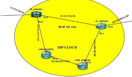
[image:2.595.321.538.230.349.2]The topology in Figure 1 below shows the simulation of a wide area network (WAN) on a GNS3 platform using multi-protocol label switching. Covenant University and Landmark University were used as case study and were assumed to have same network topology. The topology shows the Covenant University network and the Landmark University network and the Internet service provider cloud with the two core routers and the two provider edge routers.
Fig 1: Network Topology
[image:2.595.314.543.457.591.2]In a converged network, such as the simulated network illustrated above, the shortest path is usually followed. Using the simulated network, the IP_PHONE 1 and IP_PHONE 2 are trying to communicate with each other. The shortest path does not have the required amount of bandwidth to carry out the call from IP_PHONE 1 to IP_PHONE 2, so we create another path that has the required amount of bandwidth.
Fig 2: The ISP Cloud and the Interfaces Between the Provider Edge Routers and the Core Router
The end users include IP phones, printers, servers, PC computers. The figure 3 below shows the configured interface and the IP address for IP_PHONE1 using the „show interface brief‟ command.
Fig 3: The IP interface of IP_PHONE 1
[image:3.595.54.299.123.287.2]The figure below also shows the configured IP interface for IP_PHONE2 still making use of the „show interface brief‟ command.
Fig 4: The IP interfaces of IP_PHONE 2
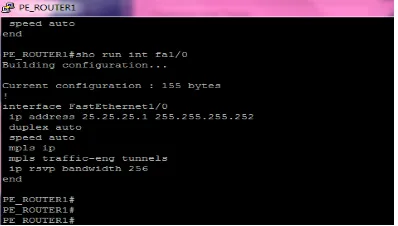
[image:3.595.316.549.267.427.2]The figures below shows the configured interfaces for the provider edge routers using the „show interface brief‟ command. The interfaces are not given in details but the IP addresses of the interfaces are given.
Fig 5: The IP interface of PE_ROUTER 1
Fig 6: The IP interface of PE_ROUTER 2
The figure below shows the details of the available bandwidth for the transfer of information from one network to another in the PE_ROUTER 1.
Fig 7: The available bandwidth in PE_ROUTER 1
[image:3.595.54.305.355.521.2] [image:3.595.316.515.496.609.2]Fig 8: The Enabling of MPLS
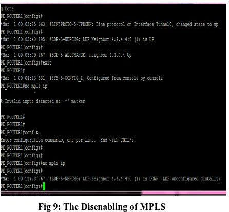
[image:4.595.316.545.70.202.2]The Figure 9 below shows the disenabling of MPLS using the „no mplsip‟ command.
Fig 9: The Disenabling of MPLS
Figure 10 and Figure 11 below show the build- up of MPLS forwarding table on core router and PE router.
Fig 11: The MPLS Forwarding Table for PE Route 1
3.
RESULTS
[image:4.595.53.276.312.519.2]The Successful ping test shows the recorded success when IP_PHONE1 with IP address 192.168.20.2, which is present in the Covenant university network is trying to ping the IP_PHONE2 which is in the Landmark University network with IP address 20.0.90.2. Figure 12 shows the path followed by the IP_PHONE 1 to IP_PHONE 2.
[image:4.595.315.546.335.492.2]Fig 12: The route followed by IP_Phone 1
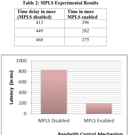
[image:4.595.312.545.412.622.2] [image:4.595.54.261.558.720.2]Table 2: MPLS Experimental Results
Time delay in msec (MPLS disabled)
Time in msec MPLS enabled
413 296
449 282
468 275
Fig 14: Bar Chart Showing Latency Per Bandwidth Control Mechanism for MPLS Disabled and MPLS
Enabled
4.
CONCLUSION
This report is based on the implementation of MPLS to improve bandwidth on a WAN. Results from the simulation has shown that the bandwidth availability in an IP network (MPLS disabled network), reduces as number of packets in the Core of the Service Provider increases while it increases significantly in an MPLS enabled network, even as number of packets in the core of the Service Provider increases. From this, conclusions can be made that MPLS is a better technique for improving bandwidth when compared with the traditional IP network.
The simulation experiment revealed that MPLS takes less time to send data from a source to its destination also, that it is more efficient than IP networks. Hence, MPLS will be more efficient if applied in the current internet architecture. With so many benefits and applications, MPLS will definitely increase its market share and will continue to be deployed in the network by the service providers and others in the future.
This research has shown that enterprises and service providers can experience an improvement in the rate of achievement of business targets by implementing and maximizing the capabilities of MPLS in their networks.
REFERENCES
[1] Webopedia, “MPLS”, retrieved from www.webopedia.com/TERM/M/MPLS.html
[2] Margaret Rouse, “What is Multiprotocol Label Switching (MPLS)?, retrieved from www.searchenterprisewan.techtarget.com
[3] Nanog, “MPLS for Dummies”, retrieved from www.nanog.org.
[4] Cisco Systems, “Multiprotocol Label Switching (MPLS)”,retrievedfrom
http://www.cisco.com/en/US/products/ps6557/products_i os_technology_home.html
[5] Top speed data communications, “MPLS-Multi-Protocol LabelSwitching”,Availableat:
http://www.topspeeddata.com/MPLS.html
[6] Broadband learning Centre. “History of bandwidth”,
Available at:
http://www.broadbandbuddy.com.au/broadband-learning-centre/history-of-bandwidth..
[7] E. Rosen; Y. Rekhter (2006), RFC 4364: BGP/MPLS IP virtual private networks (VPNs), IETF.
[8] S. Bryant; P. Pate (2005), RFC 3985: Pseudo wire emulation edge-to-edge (PWE3) architecture, IETF.
[9] L. Andersson; L. Minei; B. Thomas (2007), RFC 5036: LDP specification, IETF.
[10] Y. Rekhter; E. Rosen (2001), RFC 3107: Carrying label information in BGP-4, IETF.
[11] Sotiris I. Maniatis, Eugenia G. Nikolouzou, and Iakovos S. Venieris,”QoS Issues in the Converged 3G Wireless and Wired Networks”, IEEE Communications Magazine. August, 2002pp.44, © 2002 IEEE. ISSN:0163-6804/02.
[12] Odinma, A.C. and Oborkhale, L. 2006. “Quality of Service Mechanism and Challenges for IP Networks”. Pacific Journal of Science and Technology. Vol, 7, No.1:
pp10-16. May 2006.
http://www.akamaiuniversity.us/PJST.htm.
[13] Janusz Gozdecki, Andrzej Jajszczyk and Rafai Stankiewicz, “Quality of Service Terminology in IP Networks”, IEEE Communication Magazine, March 2003.
[14] Gero Schollmeier, Christian Winkler,”Providing Sustainable QoS in Next-Generation Networks”, IEEE Communication Magazine, June 2004.