Dual Chambered Microbial Fuel Cell For Bioelectricity
Generation From Environmental Samples
Varsha Reddy,T.
*,
Kavya,C.
*,
Krishna Prasad Reddy,K.
*,Srinivas Naik, K.
**, Sandeepta Burgula
** Department of Microbiology, Osmania university, Hyderabad – 500 007. **Centre for Plant Molecular Biology,Osmania University, Hyderabad – 500 007.
VRT, CK and KPRK contributed equally to this work.
DOI: 10.29322/IJSRP.9.05.2019.p8996
http://dx.doi.org/10.29322/IJSRP.9.05.2019.p8996
Abstract-
.
Microbial Fuel Cell(MFC) is an emerging technology which under anaerobic conditions, converts chemical energyintheorganicsubstratesto electrical energy through catalytic reactions of microorganisms. This study is aimed to generate bioelectricity using a
fabricated MFC with low cost anode and cathode materials without any toxic mediators. We devised MFC using Plain Graphite plates as electrodes.
The cathodic electrolytes used were distilled water with NaCl whereas anodic compartments were inoculated with enriched bacterial culture. Anodic
and Cathodic chambers were separated by a Proton Exchange Membrane. Current and Voltage measurements were recorded using a digital
Multimeter. The performance of MFC was analysed using Polarization Curves. Maximum Power and Current densities obtained were
91,509.7mW.cm¯² and 46.88mA.cm¯² respectively. This experimental research was targeted to understand the capability of mediator-less dual
chambered microbial fuel cell as electricity production unit
.
Index Terms
-
Anaerobic conditions, Mediator-less MFC, Graphite plates, ElectricityI.
I
NTRODUCTIONThe International Energy Agency (IEA) in 2013 estimated World energy consumption as 1.575 × 10¹⁷ kWh per year. Fossil fuels have supported the industrialization and economic growth of countries during the past century, but they cannot indefinitely sustain a global economy. The use of Fossil
fuels leads to negative environmental impacts. Therefore, newer approaches like using fuel cells have emerged as a renewable energy sources that
produces sufficient energy while at the same time reduces environmental damage. Among different kinds of fuel cells, Microbial Fuel Cells defined
as devices which directly converts microbial metabolism into electricity have attracted researcher’s attention (Allen, R.M. et al.,1993). The working
principle of MFCs is based on the tenets of microbial physiology coupled with electrochemistry. MFCs are the major type of bio electrochemical
systems which convert biomass spontaneously into electricity through the metabolic activity of the microorganisms. MFC technology has been found
as a potential technology for electricity generation.
While the first observation of electrical current generated by bacteria is generally credited to Potter in 1911, after William Grove who built the first
fuel cell in 1839, very few practical advances were achieved in this field even 55 years later (Lewis. K, 1966). The breakthrough in MFCs occurred
in 1999 when it was recognized that mediators need not to be added. The essential physical components of the MFC are the anode, cathode and
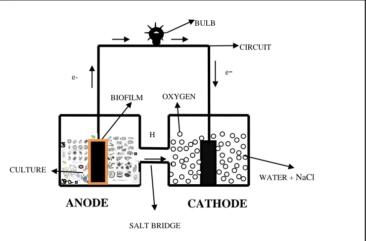
electrolyte. MFCs are typically designed as a two-chamber system (shown in Fig 1) with the bacteria in the anode chamber separated from cathode
chamber by a polymeric Proton Exchange Membrane, which often separates the liquid in the two chambers while allowing protons to pass between
the chambers. Microorganisms catalyze the oxidation of substrates releasing electrons and protons in the anode chamber. Electrons, collected on the
anode, are transported to cathode by external circuit to create current and protons are transferred through the membrane internally, to sustain the
current. Thus, due to dissimilar liquid solutions, a potential difference is produced between anode chamber and cathode chamber. Typically, the
electrons and protons react with oxygen at the cathode, to form water. The defining characteristics of an MFC includes microbially catalyzed electron
anaerobic bacteria are even able to transfer electrons extracellularly to insoluble, solid-state electron acceptors such as electrodes (DiChristina et al.,
2002).
Applications of MFCs:
The electricity produced by MFCs can be used for powering other technologies, such as biologically inspired robots, some remote devices. In
addition, the voltage generated by MFCs can be used on microbial electrolysis cells (MECs). MFCs are especially suitable for powering small
telemetry systems and wireless sensors that have only low power requirements to transmit signals such as temperature to receivers in remote
locations (Ieropoulos et al., 2005). MFCs provide a renewable hydrogen source that can contribute to the overall hydrogen demand in a hydrogen
economy.MFCs can potentially produce about 8–9 mol H2/mol glucose compared to the typical 4 mol H2/mol
glucose achieved in conventional fermentation (Liu, H., et al., 2005). MFCs were considered to be used in treating sanitary waste, food processing
wastewater, swine wastewater(Zhuwei Du, Haoran Li, 2007). MFC type of BOD sensor is used as a sensor for pollutant analysis and in situ process
monitoring and control (Picioreanu. C, et al., 2007). Microbial communities in MFCs can function as tool for bioremediation (Jeffrey M. Morris and
Song Jin., 2007). The main objective of the present study was to design an MFC which is capable of generating power simultaneously while
employing low-cost materials without using toxic mediators. The fabricated MFC system (graphite electrode without any coating) was evaluated at
ambient conditions using anaerobic mixed consortia and glucose as the sole source of electron. The current produced by an MFC is typically
[image:2.612.99.469.371.615.2]calculated in the laboratory by monitoring the voltage drop across the resistor using a multimeter.
Fig 1: Schematic diagram of a typical two-chamber MFC
BULB
H
OXYGEN
WATER + NaCl CULTURE
SALT BRIDGE BIOFILM
ANODE
CATHODE
e- e
-
MATERIALS AND METHODS
Medium Composition and inoculum source-
Samples of coal were collected to isolate electrochemically active bacteria. The collected samples were inoculated in enrichment medium (Anaerobic
media- Tryptone – 20gm/l, Dextrose – 10gm/l, Sodium Chloride – 5gm/l, Sodium thioglycolate – 2gm/l, Sodium formaldehyde sulfoxylate – 1gm/l,
Methylene blue – 0.002gm/l, Final pH at 25°c – 7.2 ±2). This medium contains Sodium thioglycolate and Sodium formaldehyde sulfoxylate that
provide adequate anaerobiosis which is indicated by methylene blue present in the medium, which gives blue colour to medium in the presence of
oxygen. Dextrose provide essential nutrients while Sodium Chloride maintains Osmotic equilibrium. For biochemical characteristic analysis of
isolated microorganisms, different media and reagents were used (Paul C. Schreckenberger, et al, 1974).
Cultivation-
One percent of the sample (which was diluted serially) was inoculated into autoclaved enrichment medium and incubated at 37°C without agitation
under anaerobic conditions. The anaerobic conditions were maintained by applying a layer (approx. 2cm) of autoclaved oil over the surface of
medium and sealed with parafilm wax. This ensures anaerobic conditions and therefore, allows the growth of only anaerobes. At the end of 72hr of
incubation, the enriched cultures were analysed for bioelectricity generation.
MFC Fabrication and Operation:
The performance of MFC largely depends on the reactor design and electrode materials. Various forms of two cell compartment electrochemical cell
may be devised to demonstrate microbial electricity generation and the one described here is one of them. The design criteria of dual chambered fuel
cell are shown in Table 1. The electrons available through the metabolism of the electron donors by microorganisms are transferred to the anode of
the fuel cell and then to the cathode through the circuit, where they reduce the oxidant, consuming protons available through the membrane from the
anode (Allen, R.M., et al., 1993). Two chambers were selected in order to avoid mixing solutions of electron acceptors and electron donors and thus
loss of electrons.
H – type two-chamber MFCs was constructed as described by Oh et al. Two polycarbonate bottles (1000ml) were linked with PVC pipe of 5cm
length, which serves as salt bridge. The salt bridge was filled with boiled and cooled Sodium Chloride (15%) solution containing 5% agar. The salt
bridge was fixed to the bottles with the aid of epoxy adhesive. The culture inoculum of bacterial strains was used as anolyte without any
pre-treatment and distilled water with added NaCl was used as a catholyte in MFC setup. Plain graphite plates (5 – 4cm; 0.3mm thick; 45.4cm²surface
area) were used as electrodes. The electrodes were positioned at a distance of 2cm on either side of the PEM. Circuit connections were set with the
copper wires fixed into the drilled holes of the electrodes and sealed with epoxy resin to avoid corrosion of copper wires. The MFC was sterilized by
thorough rinsing with Ethanol (70% v/v) and UV irradiated for 30min. The sterilized MFC chambers were filled with respective electrolytes and kept
Table 1
: Design criteria of Dual chambered mediator-less Microbial Fuel Cell
REACTOR CONFIGURATION
DUAL CHAMBER
Anode chamber
suspended growth
Anode inoculum
Mixed anaerobic
Consortia
Mediator-anode Mediator less
Working volume of anode and cathode 500ml
Electrodes Graphite plates
Surface area of electrodes 45.4cm²
Membrane PEM (salt bridge)
Operating temperature
Room temperature
Calculations:
Current density of MFC was calculated using formula: i (mA.cm¯²) = I/A
where, ‘I’ is the current measured (mA) and ‘A’ is the geometric surface area of anode (cm²). The Power density of the MFC was calculated using formula:
P (mW.cm¯²) = iV
where, ‘i’ is the current density and ‘V’ is the Voltage measured (mV).
RESULTS
Enrichment of anaerobic exoelectron generating bacteria has been reported earlier.A layer of biofilm is formed on the surface of the anodic
graphite plate. This biofilm formation helps in transfer of exoelectrons to the graphite plate. The present study shows that the microbial inhabitant of environmental sample has electrogenic potential and they can manifest this potential if they are properly re-inoculated into their habitat.
This leads to the production of bioelectricity in the fabricated MFC.
A total of seven distinct bacterial isolates were isolated from chosen environmental samples (coal) and their biochemical characteristic analysis
(using tests like IMVIC, gelatine, nitrate reduction test, urease, catalase, oxidase, Esculin hydrolysis and Sugar fermentation) were carried out
and the results are shown in Table 2. MFC constructed by using 1000ml PVC bottles and connected with 5cm long and 5cm diameter salt bridge was
used to generate electricity by microbial cell suspension cultures. Power generation in mediator-less microbial fuel cell was investigated using a
Table 2
: Results of Biochemical characteristic analysis of isolated bacteria
Organism
expected to be
Tests
For
identification
B
a
ci
ll
u
s sp
s.
A
cid
o
th
io
b
a
cil
lu
s
sp
s.
Ps
eudo
m
o
na
s s
ps
.
E
. c
ol
i
St
a
phy
lo
co
cc
us
sp
s.
C
lo
str
id
iu
m s
p
s.
Pr
o
pi
o
ni
ba
ct
er
ium
sp
s.
Gram's
staining
Gram +ve
Gram -ve
Gram -ve
Gram -ve Gram +ve Gram +ve Gram +ve
Shape
Rods
Rods
Rods
Rods
Cocci
Rods
Rods
Motility
Motile
Motile
Motile
Motile
Non-motile
Motile
Non-motile
Capsulated
-
-
+
+
+
-
-
Sporulation
+
-
-
-
-
+
-
Catalase
+
-
+
+
+
-
+
Oxidase
-
+
+
-
-
-
-
Urease
+
-
-
-
+
-
-
Indole
+
-
-
+
-
-
+
MR
+
-
-
+
+
+
-
VP
+
+
-
-
+
-
-
Citrate
utilization
+
+
+
-
+
+
-
Nitrate
reduction
-
+
-
+
+
-
-
Gelatin
hydrolysis
+
-
+
-
+
+
-
Esculin
hydrolysis
+
+
-
+
-
+
+
Starch
hydrolysis
+
-
-
-
-
-
-
Sugar
fermentation
tests
G
+
+
-
+
+
+
+
L
-
+
-
+
+
+
+
M
-
+
-
-
+
-
-
S
+
+
-
+
+
+
-
Where, G = Glucose, L = Lactose, M = Mannose, S = Sucrose.
Table 3:
Measure of Voltage, Current, Current density and Power density for a period of 21days with graphite
as electrode
Power
density(P) in
mW.cm
¯²
Current
density(i) in
mA.cm
¯²
Voltage
measured in
millivolts(mV)
Current
measured in
milliamperes(mA)
Day
S.No.
72.05
1.31
55
59.7
Day 1
1
1054.2
5.02
210
228.2
Day 2
2
1577.9
6.14
257
279.2
Day 3
3
3101.7
8.61
360
391.2
Day 4
4
4462.5
10.33
432
469
Day 5
5
5980
11.96
500
543
Day 6
6
8893.8
14.58
610
662
Day 7
7
31423.3
27.42
1146
1245.3
Day 12
8
39948.6
30.92
1292
1403.9
Day 14
9
91509.7
46.88
1952
2128.7
Day 21
10
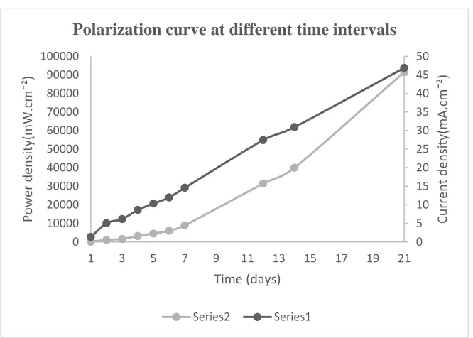
As shown in Fig.2 and Fig.3, there is an increase in Power production with increasing time period. This is due to the formation of bacterial biofilm on
the graphite surface in anode chamber. About two days after the beginning of the MFC operation, the current and power densities increased.
Probably, this period was required by the microorganisms to adapt to the culture medium, to begin to adhere to the graphite plate, and to produce the
biofilm. The Power density was directly dependent on the biofilm development. The spreading property of biofilm is especially useful for MFC
efficiency because it means that the number of electrons transferred to the anode is directly proportional to the anode’s surface area given minimal
loss of electrons due to close proximity between the biofilm and the anode (Kim BH, et al., 2003). The maximum Current density and Power density
[image:6.612.78.411.496.734.2]was 46.88mA.cm¯² and 91,509.7mW.cm¯².
Fig. 2: Polarization curve to show Power generation in MFC
0 5 10 15 20 25 30 35 40 45 50 0 10000 20000 30000 40000 50000 60000 70000 80000 90000 100000
1 3 5 7 9 11 13 15 17 19 21
Cur
re
nt
de
ns
ity(m
A.
cm
¯²)
Po
we
r d
en
sit
y(
m
W
.c
m
¯²
)
Time (days)
Polarization curve at different time intervals
Where, series 1 represents Current density and series 2 represents Power density
Fig.3: A curve showing an increase in volts in MFC
CONCLUSION
Microscopic, Morphological and Biochemical characteristic analysis revealed the presence of seven different microorganisms which include aerobes,
anaerobes and facultative anaerobes. The results revealed the feasibility of bioelectricity generation using a fabricated MFC with low cost anode
materials (non-coated plain graphite electrodes), without any toxic mediators. It can hence be stated that the potential electrogenic bacteria can be
easily procured from environment and deployed in MFCs for an eco-friendly and economically viable method of electricity generation. Maximum
Current and Power densities obtained using anaerobic consortia in this experiment were 46.88mA.cm¯² and 91,509.7mW.cm¯². Although MFCs are a
promising technology for renewable energy production, they face several challenges, as well.
ACKNOWLEDGMENTS
The authors gratefully acknowledge the Department of Microbiology, Osmania University for providing the necessary facilities to carry out the
present study.
REFERENCES
[1] Allen, R.M., and Bennetto, H.P. (1993). Microbial Fuel Cell. Electricity Production from Carbohydrates. Applied Biochemistry and
Biotechnology, Vol.37 No.39/40, pp 27-40.
0
500
1000
1500
2000
2500
0
10
20
30
Curve for Days vs Volts
Volts
Time (days)
Vo
ferE, a homolog of the pulE (gspE) type II protein secretion gene. J. Bacteriol.,184: 142-151.
[4] Du, Z., Li, H., Gu, T. (2007). A state of the art review on microbial fuel cells: A promising technology for wastewater treatment and
bioenergy. Biotechnology Advances 25, 464-482.
[5] Gil, G.C., Chang, I.S., Kim, B.H., Kim, M., Jang, J.Y., Park, H.S., Kim, H.J. (2003). Operational parameters affecting the performance of a
mediator-less microbial fuel cell. Biosensors and Bioelectronics 18, 327-334.
[6] Ieropoulos et al., (2005). Comparative study of three types of microbial fuel cell. Enzyme Microb. Technol., 37 (2) (2005), pp. 238-245.
[7] Jadhav, G.S. and M.M. Ghangrekar,. (2008). Improving performance of MFC by design alteration and adding cathodic electrolytes. Applied
Biochem. Biotechnol., 151: 319-332.
[8] Jeffrey, M., Morris and Song Jin. (2007) Feasibility of using MFC technology for bioremediation of hydrocarbons in groundwater. Journal
of Environmental Science and Health Part A 43(1):18-23.
[9] Kim, H. J., Hyun, M. S., Chang, I. S., & Kim, B. H. (1999). A microbial fuel cell type lactate biosensor using a metal-reducing bacterium,
Shewanella putrefaciens. Journal of Microbiology and Biotechnology, 9(3), 365-367.
[10] Kim, B.H., Chang, I.S., Gil, G.C., Park, H.S., Kim, H.J. (2003). Novel BOD (biological oxygen demand) sensor using mediator-less
microbial fuel cell. Biotechnol Lett 25: 541-545.
[11] Lewis, K., (1966). Symposium on bio electrochemistry of microorganisms. Bacteriology Reviews, 30(1): 101-113.
[12] Lim, S.S., Jahim, J.M., Wan Daud, W.R., Ismail, M., Anuar, N., Kamarudin. S.K., and Shari. S.N. (2010). Optimization of electricity
generation and palm oil mill effluent (POME) treatment from microbial fuel cell. J. Applied Sci., 10: 3335-3360.
[13] Liu, H., Grot, S., Logan, B.E. (2005). Electrochemically assisted microbial production of hydrogen from acetate, Environmental Science &
Technology 39, 4317–4320.
[14] Logan, B.E., Hamelers, B., Rozendal, R., Schröder, U., Keller, J., Freguia, S., Aelterman, P., Verstraete, W., Rabaey, K. (2006). Microbial
fuel cells: methodology and technology. Environmental Science & Technology 40, 5181-5192.
[15] Logan, B.E. (2009). Exoelectrogenic bacteria that power microbial fuel cells. Nature Reviews Microbiology 7, 375-381.
[16] Mathuriya, A.S. and V.N. Sharma. (2008). Bioelectricity production from paper industry waste using a microbial fuel cell by Clostridium
species. J. Biochem. Tech., 1: 49-52.
[17] Patil, V.D., Patil, D.B., Deshmukh, M.B., and Pawar. S.H. (2011). Comparative study of bioelectricity generation along with the
treatment of different sources of wastewater. Int. J. Chem. Sci. Appl., 2: 162-168.
[18] Paul, C., Schreckenberger and Donna J. Blazevic, (1974). Rapid methods for Biochemical testing of anaerobic bacteria. Applied
Microbiology, Nov. 1974, p. 759-762.
[19] Potter, M. (1911). Electrical effects accompanying the decomposition of organic compounds. Proceedings of the Royal Society of London.
Series B, Containing Papers of a Biological Character (1905-1934), 84(571), 260-276.
[21] Picioreanu, C., Head, I. M., katuri, K. P., Van Loosdrecht, M.C.M., and Scott, K. ‘A. (2007).Computational model for biofilm-based
MFCs’. Water Research.
[22] Rabaey, K. and Verstraete W. (2005). Microbial fuel cells: novel biotechnology for energy generation. Trends in Biotechnology 23,
291-298.
[23] Shantaram, A., Beyenal, H., Veluchamy, R. and Lewandowski, Z. (2005). Wireless sensors powered by microbial fuel cells. Environmental
Science and Technology 39, 5037-5042.
[24] Shukla, A., Suresh, P., Berchmans, S. and Rajendran, A. (2004). Biological fuel cells and their applications. Current Science 87, 455-468.
[25] Zhuwei, D.u., Haoran, Li. A.(2007) .Promising technology for wastewater treatment and bioenergy. Biotechnology advances 25 464-482.
[26] Zhou, M., Chi, M., Luo, J., He, H., Jin, T. (2011). An overview of electrode materials in microbial fuel cells. J Power Sources 196:
4427-4435.
Authors
T Varsha Reddy, M.Sc: Department of Microbiology, Osmania university, Hyderabad – 500 007.
C Kavya, M.Sc: Department of Microbiology, Osmania university, Hyderabad – 500 007.
K Krishna Prasad Reddy, M.Sc: Department of Microbiology, Osmania university, Hyderabad – 500 007.
K Srinivas Naik, M.Sc., Ph.D: Centre for Plant Molecular Biology,Osmania University, Hyderabad – 500 007.
Sandeepta Burgula, M.Sc, Ph.D : Department of Microbiology, Osmania university, Hyderabad – 500 007.
Note: TVR, CK and KKPR have contributed equally to this work.
Correspondence Author: Sandeepta Burgula, Department of Microbiology, Osmania University, Tarnaka, Hyderabad- 500007 Tel: +91-40-27090661; Mobile phone: 9848056930