Development of a Novel Robust Differential Maximum
Power Point Tracking (MPPT) Method
Tafiq Ahmed *, Mohammad Liton Hossain**
*
Electrical Engineering, University of Rostock, Germany
* *
Computational Science and Engineering, University of Rostock, Germany
DOI: 10.29322/IJSRP.8.5.2018.p7729 http://dx.doi.org/10.29322/IJSRP.8.5.2018.p7729
Abstract- The use of photovoltaic (PV) systems is increasingly growing in importance since they involve an exploitation of solar radiation constituting an energy source which is renewable, available in most places, and pollution-free. Despite their numerous advantages, PV systems have two major drawbacks: low energy conversion efficiency and loss of energy due to variations in meteorological conditions; for this reason, Maximum Power Point Tracking (MPPT) control techniques play a key role in exploiting the maximum energy caught by PV modules. The output characteristic of a photovoltaic array is non-linear and changes with solar irradiation and the cell’s temperature. Therefore, a Maximum Power Point Tracking (MPPT) technique is needed to draw peak power from the solar array to maximize the produced energy. In this study we have analyzed the Maximum Power Point Tracking (MPPT) method and finding out a new and easier way to track maximum power point (MPP) and also our study is focused to overcome the drawbacks of MPPT. This research paper presents a novel MPP tracking method for tracking exact Maximum Power Point (MPP) if the irradiation or load changes.
Index Terms- Irradiance, MPP, MPPT, PO, PV I. INTRODUCTION
M
aximum Power Point Tracking (MPPT) is a technique which is used commonly with photovoltaic (PV) solar systems to maximize power extraction under all conditions [1]. MPPT is not a mechanical tracking system that “physically moves” the modules to make them point more directly at the sun. MPPT is a fully electronic system that varies the electrical operating point of the modules so that the modules are able to deliver maximum available power.As PV solar panel efficiency is low, so it is very important that load works in maximum power. Otherwise power losses occur. In PV solar system, it is not necessary that the load works in the maximum power. That is why it’s necessary to track the maximum power point so that load can work at that point for reducing power losses. In this study we have considered the challenge to minimize the power losses of existing solar systems and another challenge to track the maximum power.
Due to changes in irradiation the load characteristics also changes as a result the efficiency of the whole system is also variable.
Our main focus of this study is as follow:
• To investigate and track the maximum power point in present solar system and find the suitable and stable way for tracking MPP.
• To learn and study about algorithms for tracking maximum power point.
II. METHODOLOGY
A. MPP Tracking Methods
Over the past decades many methods to find the MPP have been developed and published. These techniques differ in many aspects such as required sensors, complexity, cost, range of effectiveness, convergence speed, correct tracking when irradiation and/or temperature change, hardware needed for the implementation. Some popular MPPT algorithms are Perturb and Observation, Incremental Conductance, Fractional Open Circuit Voltage, Fractional Short Circuit Current etc.
Perturb and Observation MPPT Algorithm:This algorithm is an iterative technique and very simple one. It measures the panel operating voltage and current periodically and calculates the instantaneous power p(n). This instantaneous power compares with the previous output power P(n)-P(n-1), then the operating voltage X(n+1) is determined and changed by changing the duty ratio of the converter X(n+c) or X(n-c). The sign of change of output power is also observed to track the MPP. This method has some drawbacks as well: The operating point continues to oscillate around the MPP, resulting in PV power losses, The P&O fails to work properly under a sudden increase in insolation level, exhibiting erratic behavior, It lacks accuracy in finding whether the MPP is reached.
III. PROPOSEDMETHOD
A. Proposed MPP Tracking Technique:
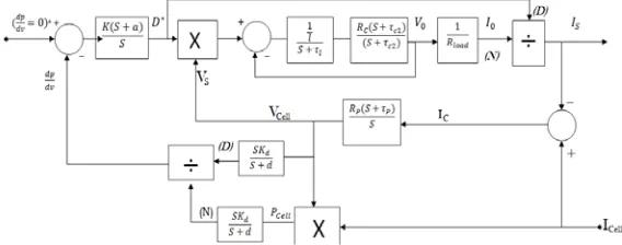
[image:2.612.39.296.166.270.2]Analyzing all popular algorithms and technique we have proposed a robust optimization 1st order close loop differential MPP tracking method which is controlled by PI controller. We have developed this method to track MPP whether the radiation or load changes. Here is the block diagram of our proposed method
Figure 1: Model of MPPT using block diagram
The Figure 1 shows PV system block diagram with MPPT Technique. It consists of PV array, Buck converter, MPPT block, and finally load. Combination of Series and parallel solar cells constitute PV array. Series connection of solar cells boost up the array voltage and parallel connection increases the current. In order to change the input resistance of the panel to match the load resistance (by varying the duty cycle), a DC to DC converter is required. Buck converter is used to obtain more practical uses from solar panel. The input of buck converter is connected to PV array and output is connected to load [12]. MPPT block receives VPV and IPV signals from PV array. The output of MPPT block is going to the PI controller. Then from PI controller these pulses are given to buck converter. Converter works based on these pulses to make the PV system operate at Maximum power point (MPP) [3]. The heart of the model is MPPT block which is working through the PI controller helps in finding the maximum operating point of the solar panel. This can be done by using a robust 1st order close loop differential MPPT method
B. Modeling of MPPT
The proposed circuit needs independent dc source which is supplied from photovoltaic cell. The inputs are fed by voltage and current of the PV terminals, while the output provides duty cycle for the buck converter. Buck converter controls the output voltage by varying the duty cycle k, of the switch. This is calculated using the formula
V0= KVS.
If we vary the pulse width of the pulse generator various voltage ranges at the output can be obtained. Once the buck converter injected the power from the PV panel and the PI controller starts function, it varies the value of duty cycle which will change the input value that is sensed by the PI controller. By using the PI controller the error has been minimized in the system and the efficiency is improved [12].
C.MPPT implementation
MPPT implementation is a close loop system. Here dP
dV= 0 goes
to dc/dc buck converter. From PV array Icell and Pcell is goes through the differentiator and PI controller forcefully maintain that dPdV is equal to zero (0). The controlling block diagram is given bellow:
IV. ANALYSIS AND SIMULATION
A. Simulation Circuit diagram of MPPT tracking in PSIM
In this paper, the simulation model is developed with PSIM. The proposed circuit needs independent dc source which is supplied from photovoltaic cell. The inputs are fed by voltage and current of the PV terminals, while the output provides duty cycle for the buck converter. Buck converter controls the output voltage by varying the duty cycle k, of the switch. Which is calculated using the formula𝑉0=𝐾𝑉𝑆. If we vary the pulse width of the pulse generator various voltage ranges at the output can be obtained. Once the buck converter injected the power from the PV panel and the PI controller starts function, it varies the value of duty cycle which will change the input value that is sensed by the PI controller. By using the PI controller the error has been minimized in the system and the efficiency is improved [12].
[image:2.612.317.601.348.460.2]Figure 3: Simulation circuit of solar panel with MPPT block The model shown in figure 3 represents a PV solar panel connected to resistive load through a DC/DC Buck converter. The DC-Buck boost system specifications are given as follows_
Load Resistance, RLoad= 1.5Ω.
Buck inductance, L= 500μH ; Resistance, RL= 10mΩ Buck capacitor, Cc= 47μF; Resistance, Rc= 1mΩ.
Here in the block there are two differentiator. One is connected to the PCell and another is connected to the VCell. Now the specifications are given_
Power diff. resistor, R1P= 20Ω ; R2P= 100 Ω Power diff. capacitor, CP= 10nF
Voltage diff. resistor, R1V= 20Ω ; R2V= 100 Ω Voltage diff. capacitor, CV= 10nF
PI controller gain (K)= 10000 and a= 0.1 Now here is the panel parameter below_
Table 1: The parameters of 60w solar panel 60W Solar Panel
Sr. no
Parameter Value 1 Number of cell Ns= 36 2 Standard radiation 1000w/m2 3 Series resistance Rs= 0.008Ω 4 Shunt resistance Rsh= 1000Ω 5 Short circuit current Isc= 3.8A 6 Open circuit voltage Voc= 21.1V
B. Irradiance Effect
Effect of Decreasing Irradiance:
In solar panel irradiance is not constant, it is changeable. If it is cloudy day then irradiance effect is decreasing. Then it is very important to track that MPP. On that condition dP
dV= 0 is
required. The output power of the solar panel varies with the irradiance. Solar power is high at high value of solar irradiance & it starts decreasing as the solar irradiance value decreases.
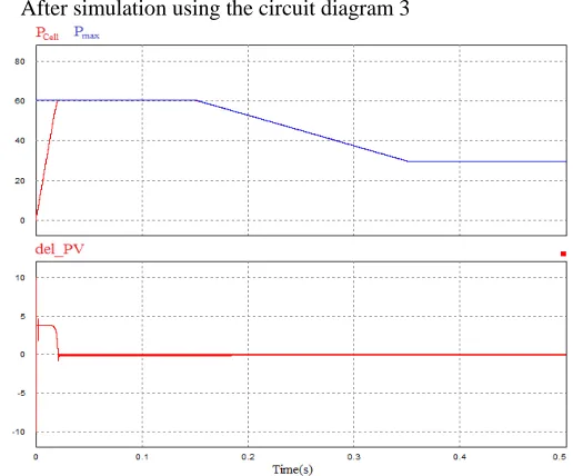
[image:3.612.44.297.61.234.2]After simulation using the circuit diagram 3
Figure 4: MPP track when the irradiance is low Here in the figure, when irradiance is low then on the upper portion PCell track the Pmax and in lower portion 𝑑𝑃�𝑑𝑉 track the zero(0) point. If 𝑑𝑃�𝑑𝑉= 0 then power will be maximum. That mean PCell track the Pmax. It is clear from waveform that even though solar irradiance varies output remains constant. This is because of PI controller and novel robust differential MPPT method.It is also necessary that Load can work at that maximum power. This is shown in below simulation figure.
Figure 5: Load is working in maximum power point
Increasing Irradiance Effect
:
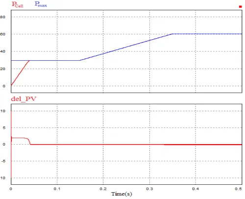
When it is sunny day then irradiance effect is high. Then it is also necessary to track MPP for minimize power loss. On that condition dP [image:3.612.332.569.434.566.2] [image:3.612.30.278.490.620.2]Figure 6: MPP track when the irradiance is high Here in the figure, when irradiance is high then on the upper portion PCell track the Pmax and in lower portion dP�dV track the zero(0) point. If dP�dV= 0 then power will be maximum. That mean PCell track the Pmax. Load must have to work at that maximum power when the irradiance is high. This is shown in below simulation figure.
Figure 7: Load is working in maximum power point
C. Load Changing Effect
It is very difficult to track MPP when load is changed. Because when load is changed power consumption fluctuate at instant. That is why is too difficult to track MPP. But using PI controller and 1st order close loop differential MPPT method can easily track maximum power point.
Here is the changing load is Rload = 1Ω
[image:4.612.326.576.62.286.2]Now load changing effect is shown in the below figure _
Figure 8: MPP is tracked when the load is changing Here in this figure…..though load is changed on the upper portion Pcell easily track the Pmax and also dP�dV is equal to zero (0) is shown in the lower portion.
V. RESULT ANALYSIS
We have found a new MPP tracking method which is controlled by PI controller. This new method name is “Novel Robust Differential MPP Tracking Method”. Using this method through the PI controller we can easily track the maximum power point.
A. Irradiance Effect
The output power of solar panel with MPPT block with respect to solar irradiance level is as shown in the figure 4 and 6. It is clear from the figure that the output power of the solar panel varies with the irradiance. Solar power is high at high value of solar irradiance & it starts decreasing as the solar irradiance value decreases.
Now here is the result justifying table_
Table 2: Result justification on irradiance varies Sr.No X-axis (Time in second) Y-axis(Power in watt)
1 0.0 0.0
2 0.0066 20 3 0.0133 38
4 0.02 60
5 0.10 60
6 0.15 58
7 0.20 48
8 0.30 38
9 0.35 31
[image:4.612.40.299.377.510.2] [image:4.612.309.583.591.732.2]From the table 2 it is shown that at X-axis when time is between 0(zero) s to 0.2 s Pcell couldn’t track the Pmax. This is the error of this method. But on the other side 0.02 s is very small time. So this small time couldn’t create any effect on the output result. After that small time maximum power point is tracked exactly by Pcell. That mean it takes time 20ms to track maximum power point.
B. Load Changing Effect
Output power of solar panel of with MPPT block varies with respect to the changing of load. By using PI controller to track maximum power Pmax in MPPT method while the load is changing, as shown in figure 8
PI controller forcefully create dP
dV is equal to 0(zero) and that is
why load can track the maximum power point. This is shown in figure 8
Now here is the result justifying table
Table 3: Result justification on changing load Sr.No Time in
s(X-axis) Pcell(Y-axis)W I1(Y-axis)A PV(Y-axis) 1 6.66ms 10 0 3.5 2 13.33ms 40 0 3.4
3 20.00ms 60 8 0
4 26.66ms 60 8 0 5 33.33 60 8 0 6 200ms 60 11 0 7 300ms 60 11 0 8 400ms 60 11 0 9 500ms 60 11 0 From the table 3 it is clear that from time 0 (zero) to time 0.02 there is some error. On that time Pcell,I1 and ∆PV is not expected value. But after that point all three Pcell,I1 and ∆PV is expected value. That mean system takes 20ms to track maximum power point. After that small time load can easily track the maximum power point and PI controller forcefully create dP
dV is
equal to 0(zero).
VI.
CONCLUSIONPower generation method using solar photovoltaic module is a foremost effective technique of using the solar energy. In this method solar panel directly convert sunlight irradiation into electricity by the photoelectric effect. It is clean and pollution-free. MPPT algorithms used in PV systems are one of the most important factors affecting the electrical efficiency of system. As a result of cost optimization, after decided to use an MPPT system, it is important to decide which technique or method will be used in application [10]. After studying MPPT techniques , it is clear that it can be very difficult to choose the best; each MPPT method has its own advantages and disadvantages and the choice is highly application dependent. That’s why MPPT algorithms are not suitable for tracking MPP [11].
Analyzing these methods we find out an easier new method
which is controlled by PI controller. The name of this method is “Novel robust differential maximum power point tracking method”.
The output power of the solar panel varies with the irradiance. Solar power can be high when irradiance is high or power can be low when irradiance is low. So it is difficult to track MPP. One the other hand when load is varying the output is varying at instant. That is why it is more difficult to track maximum power point than irradiance varying. So it is important to use a robust and cost effective method. Using this Novel robust differential maximum power point tracking method through PI controller, we can track maximum power point perfectly whether it is irradiance effect or load change effect or temperature effect on PV panel.
ACKNOWLEDGMENT
At first all thanks goes to almighty creator who gives me the opportunity, patients and energy to complete this study. I would like to give thanks to Mr. Ahmed Al Mansur; Assistant Professor at Green University of Bangladesh. I have found always immense support from them to keep my work on the right way. His door was always open for me, when I have got myself in trouble.
Finally, I must express my very profound gratefulness to my parents and to my wife for providing me with constant support and encouragement during my years of study and through the process of researching and writing this paper. This accomplishment would not have been possible without them. Thank you.
REFERENCES
[1]”A Survey of Maximum PPT techniques of PV Systems”, IEEE Xplore, Retrieve 2016-10-04
[2] “Maximum Power Point Tracking”, available online at: https://en.wikipedia.org/wiki/Maximum_power_point_tracking
[3] P. A. Lynn, Electricity from Sunlight: An Introduction to Photovoltaics, John Wiley & Sons, 2010, p. 238.
[4] T. Markvart, Solar electricity, Wiley, 2000, p. 280.
[5] G. M. S. Azevedo, M. C. Cavalcanti, K. C. Oliveira, F. A. S. Neves, Z. D. Lins,
"Evaluation of maximum power point tracking methods for grid connected photovoltaic
systems," in Proc. IEEE PESC, 2008, pp. 1456-1462.
[6] T. Esram, P.L. Chapman, "Comparison of Photovoltaic Array Maximum Power Point Tracking Techniques," IEEE Transactions on Energy Conversion, vol. 22, no. 2, June 2007, pp. 439-449.
[7] Mammano, Robert. "Switching power supply topology voltage mode vs. current mode." Elektron Journal-South African Institute of Electrical Engineers, 18.6 (2001): 25-27.
[8] Laplante,Philip A, “Comprehensive Dictionary of Electrical Engineering”, 2nd Ed.CRC Press, 2005, ISBN1420037803, p. 190
[09] PID Controller, available on-line at:
[10] Nevzat Onat, “Recent Developments in Maximum Power Point Tracking Technologies for Photovoltaic Systems” International Journal of Photoenergy Volume 2010 (2010)
[11] Saleh Elkelani Babaa, Matthew Armstrong, Volker Pickert “Overview of Maximum Power Point Tracking Control Methods for PV Systems”, Journal of Power and Energy Engineering, 2014, 2, 59-72
[12] Shiba Arora, Pankaj Sharma, “Modeling & Similation of Photovoltaic System to Optimize the Power Output Using DC-DC Converter”,
International Journal of Advanced Research in Electrical, Electronics and Instrumentation Engineering
AUTHORS
Author – Tafiq Ahmed, M.Sc in Electrical Engineering in University of Rostock, Germany;
Email: [email protected]
Second Author: Mohammad Liton Hossain,
M.Sc in Computational Science and Engineering, University of Rostock, Germany. Lecturer at Institute of Science and Technology (IST), Bangladesh.