Starting, Steady-State Modelling and Simulation Studies
Of Single-Phase Transfer-Field Reluctance Motor,
Operating In the Asynchronous Mode
Obute K.C. 1, Agu V.N. 1, Anazia E.A 1, Okozi S.O. 2, Anih L.U. 3
1
Department of Electrical Engineering, Nnamdi Azikiwe University Awka, Anambra State, Nigeria
2
Department of Electrical/Electronic Engineering, Federal University of Technology, Owerri, Imo State, Nigeria.
3
Department of Electrical Engineering, University of Nigeria Nsukka, Enugu State, Nigeria.
Abstract- The work presents starting, steady-state modelling and simulation studies of single-phase transfer field reluctance motor operating in the asynchronous mode from which the performance indices could be predicted. The machine is made up of two similar motors that are integrally wound and mechanically coupled together, but with their pole axes 0.5π degree out of phase in space. The transfer field machine in general is a low speed machine operating at half the synchronous speed of a normal induction machine. The equivalent circuit of the machine is derived using d-q-o transformation fundamentals. The speed range of the machine unlike the normal induction machine counterpart with slip range 0 < s < 2, has a corresponding slip range 0.5 < s < 1.5. The simulation results reveal a good similarity in its steady state characteristics with that of the existing normal single phase induction motor counterpart. Obviously, all single phase asynchronous motors are not self starting. They suffer the severe problem of getting the rotor rotate when started. The designed value of capacitor necessary for satisfactory starting performance of the machine is also discussed. Due to its inherent half speed characteristics, the possible areas of application are limited and are also suggested in the work.
Index Terms- asynchronous mode, single-phase transfer field machine, induction machine, slip, half-speed, clockwise rotating field, counter-clockwise rotating field.
I. INTRODUCTION
asically, the asynchronous machines are those machines whose rotors rotate at speeds other than the synchronous speed of the rotating magnetic field in the air gap (Obute et al 2010). These machines are notably induction machines and transfer field machines. The asynchronous machine is reversible in the sense that it can operate as either a motor or a generator at a time. The mode of operation of the machine is a function of the speed of the rotating field in relation to the rotor. In reality, all asynchronous machines are basically motors. The single phase operation of the induction motor dates over several decades ago. However, the single phase operation of transfer field reluctance motor is new and gradually gaining ground in literature. In general, a reluctance machine is an electric machine in which torque is produced by the tendency of a movable part to move into a position where the inductance of an energized phase
winding is a maximum. The single phase transfer field reluctance machines are basically single-phase induction motors built with variable air-gap reluctance and with no d.c. supply on the rotor. The machine in its most primitive form comprises two identical salient-pole machines (A&B) whose rotors are mechanically coupled together but with their pole axes displaced by 0.5π electrical radians in space. Each machine unit has two sets of windings, identifiable as main and auxiliary windings respectively. The main windings of both machines are connected in series. The auxiliary windings are also connected in series but are transposed and short-circuited. No winding (conductor) is necessary in either of the rotors. The pictorial/connection diagrams are shown in fig. 1 (a and b) respectively. This class of machines has a peculiar advantage over the normal induction motor counterpart from the control point of view, since the auxiliary winding terminals, which act as the rotor conductors in normal induction machines are readily available without the use of slip-rings or current gears (Agu 1978).
(a)
Where
II = Main winding current of machine A and B, I2 = Auxiliary winding current of machine A and B, XmA, = Main winding reactance of machine A, XMB = Main winding reactance of machine B, XaA, = Auxiliary winding reactance of machine A, XaB, Auxiliary winding reactance of machine B, V = Supply voltage.
Fig. 1a – The pictorial diagram of transfer field reluctance motor (Courtesy of machine laboratory University of Nigeria Nsukka)
b – The connection diagram of transfer field reluctance motor
II. EQUIVALENT CIRCUIT OF SINGLE PHASE TRANSFER FIELD RELUCTANCE MOTOR
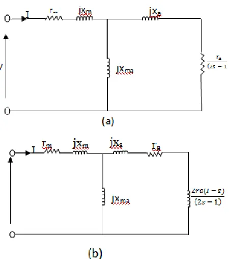
In the course of developing the equivalent circuit of single phase transfer field motor, fig. 1b is redrawn for clarity and then analysed as shown in Fig. 2 (a/b) below:
Fig. 2 - Modified circuit models of single phase transfer field reluctance motor
a) – Motor under standstill condition (s = 1)
b) – Motor under running condition at variable slip (2s-1) From fig 2a,
V1 = I1(R1+R2) +I2 xd -I2xq+I1(xd+xq) = I1 (R1+R2) +I1 (xd +xq)+I2(xd-xq)
…1 Since windings are identical, R1 = R2
∴V1 = 2I1R1+I1 (xd +xq-xd+xq) +I1 (xd -xq)+I2(xd-xq) = 2I1R1+ 2xqI1+(xd -xq) [I1+I2] = (2R1+ 2xq)I1+(xd -xq) [I1+I2]
...2 Similarly, from fig 2b,
V2 = I2(R1+R2) +(2s-1)xd I1-(2s-1)xqI1 +(2s-1)xdI2+(2s-1)xqI2 …3
Since windings are identical, R1 = R2
∴V2 = 2R2I2+I2[(2s-1)xd +(2s-1)xq]+I1 [(2s-1)xd- (2s-1)xq]
𝑉𝑉2
(2𝑠𝑠−1) = (2𝑠𝑠−1)2𝑅𝑅2𝐼𝐼2 + I2 [xd+ xq]+ I1[xd- xq ]
⇒ 𝑉𝑉2
(2𝑠𝑠−1) =
2𝑅𝑅2𝐼𝐼2
(2𝑠𝑠−1) +I2 (xd+ xq- xd+ xq )+ I2 (xd- xq)+I1 (xd- xq ) ⇒ (2𝑠𝑠−1)𝑉𝑉2 = (2𝑠𝑠−1)2𝑅𝑅2𝐼𝐼2 + 2xqI2 +(xd- xq) [I2+ I1]
𝑉𝑉2
(2𝑠𝑠−1) = �
2𝑅𝑅2+2𝑥𝑥𝑞𝑞
(2𝑠𝑠−1) � I2 +(xd- xq) [I2+ I1] ….4
Fig. 3 - Equivalent circuit of single-phase reluctance motor Since the auxiliary winding of Fig. 1b is short-circuited; then fig. 3 yields 𝑉𝑉2
2𝑆𝑆−1=𝑜𝑜.
Hence Fig 3 is redrawn as below;
Fig 4 - Equivalent circuit of the machine when the output voltage 𝑉𝑉2
[image:3.612.321.546.62.316.2]2𝑆𝑆−1 of Fig 3 is shorted.
Table 1 – Parameters of the experimental machine of fig. 1
Parameter Value
Lmd 133.3mH
Lmq 25.6mH
Lm = La 25.6mH
Ls 24mH
rm = ra 3.0Ώ
rs 2.5Ώ
V 220V
F 50Hz
J 1.98 x 10⁻³ kgm3
No of poles P 2
From fig. 4 and table 1.
If 2R1 = rm, 2Xq = Xm = Xa
2R2 = ra, Xd – Xq = Xma, NB - (X=2πFL)
Then fig. 4 can be redrawn as below;
Fig. 5 (a/b) – Steady-state equivalent circuits of single phase transfer field motor with the machine parameters.
III. ROTOR SLIP WITH RESPECT TO TWO ROTATING FIELDS. All single phase asynchronous motors suffer from a severe handicap. Since there is only one phase on the stator winding, the magnetic fields in all single-phase asynchronous motors do not rotate. Instead it pulses, getting first larger and then smaller, but always remaining in the same direction. Because there is no rotating stator magnetic field, all single-phase asynchronous motors have no starting torque.
However, once the rotor begins to turn, an induced torque will be produced in it. This stationary pulsating magnetic field of single phase motor can be resolved into two rotating magnetic fields, each of equal magnitude but rotating in opposite directions. The motor responds to each magnetic field separately, and the net torque in the machine will be the sum of the torques due to each of the two magnetic fields (Stephen Chapman 2005). The flux density (Bs) of the stationary magnetic field is given by,
Bs(t) = Bmax cosωt …1
A clockwise-rotating magnetic field (Bcw) can be expressed as;
Bcw(t)= (0.5 Bmax cosωt) 𝑖𝑖̂+(0.5 Bmax sinωt) 𝑗𝑗̂ …2
Similarly, a counter clockwise –rotating magnetic field (Bccw) can be expressed as;
Bccw(t) = (0.5 Bmax cosωt) 𝑖𝑖̂ + (0.5Bmaxsinωt)𝑗𝑗̂ …3
Hence, equation 1 becomes;
Bs(t)= Bcw(t) + Bccw(t) …4
For the single phase transfer field reluctance motor, the reaction between the fields created by the current in the main winding, causes the rotation of the rotor. The difference between the rotor speed (ωr) and the synchronous speed (ω) is the slip(s), usually given as a percentage of the synchronous speed.
characteristic features of single phase reluctance motor is similar to that of a normal induction motor counterpart, but with synchronous speed being half that of the normal synchronous motor.
If we let us suppose that;
ωR = synchronous speed of the transfer field motor, then from the foregoing expression;
ωR = 0.5ω …5
Generally, for normal induction machine, slip s, ωr and ω are related by;
ωr = ω (1-s) … 6
Similarly, for the half speed machine of our concern, the slip (Scw) with respect to clockwise rotating field is given by;
Scw =
𝜔𝜔𝑅𝑅−𝜔𝜔𝑟𝑟
𝜔𝜔𝑅𝑅 …7
By substituting equation 5 into equation 7, we have; Scw = 𝜔𝜔−2𝜔𝜔𝑟𝑟𝜔𝜔 ….8
Also, the rotor direction of rotation is in opposition to that of the counter clockwise rotating field, therefore, the slip (Sccw) with respect to the counter clockwise rotating field is;
Sccw = 𝜔𝜔𝑅𝑅−(−𝜔𝜔𝑟𝑟𝜔𝜔 ) 𝑅𝑅 =
𝜔𝜔𝑅𝑅+𝜔𝜔𝑟𝑟
𝜔𝜔𝑅𝑅 …9 By substituting equation 5 into 9, we have; Sccw =
𝜔𝜔+2𝜔𝜔𝑟𝑟
𝜔𝜔 …10
Hence, substituting equation 6 into 8 and 10, we have; Scw =
𝜔𝜔−2𝜔𝜔(1−𝑆𝑆) 𝜔𝜔
= 2s – 1 …11
Similarly, Sccw = 𝜔𝜔+2𝜔𝜔 (1−𝑆𝑆)𝜔𝜔
= 3 – 2s …12
If the clockwise and counterclockwise rotation of the machine at slip s is considered, then fig 5a is modified as below;
Fig. 6 – Modified equivalent circuit of single phase transfer-field reluctance machine rotating at slip s
From the modified equivalent circuit of fig. 6, let Zcw and Zccw be the impedances due to clockwise and counter clockwise rotating field respectively.
Hence, Zcw =
�0.5𝑟𝑟𝑟𝑟2𝑆𝑆−1+ 𝑗𝑗0.5𝑋𝑋𝑟𝑟� (𝑗𝑗 0.5𝑋𝑋𝑚𝑚𝑟𝑟)
�0.5𝑟𝑟𝑟𝑟2𝑆𝑆−1+ 𝑗𝑗0.5𝑋𝑋𝑟𝑟�+(𝑗𝑗0.5𝑋𝑋𝑚𝑚𝑟𝑟) …13
Zccw =
�0.5𝑟𝑟𝑟𝑟3−2𝑆𝑆+ 𝑗𝑗0.5𝑋𝑋𝑟𝑟�(𝑗𝑗 0.5𝑋𝑋𝑚𝑚𝑟𝑟)
�0.5𝑟𝑟𝑟𝑟3−2𝑆𝑆+ 𝑗𝑗0.5𝑋𝑋𝑟𝑟�+(𝑗𝑗0.5𝑋𝑋𝑚𝑚𝑟𝑟) ...14 Similarly, for the series arm, let Zm = rm + jxm ..15
∴ Total impedance of the circuit ZT = Zm+Zcw+Zccw …16
⇒ I = 𝑍𝑍𝑉𝑉
𝑇𝑇 …17 More-still, by current division principle;
iacw = �
𝑗𝑗 0.5𝑋𝑋𝑚𝑚𝑟𝑟
�0.5𝑟𝑟𝑟𝑟2𝑆𝑆−1+𝑗𝑗 0.5𝑋𝑋𝑟𝑟�+ (𝑗𝑗 0.5𝑋𝑋𝑚𝑚𝑟𝑟)� 𝐼𝐼 …18 Similarly;
iaccw = � 𝑗𝑗 0.5𝑋𝑋𝑚𝑚𝑟𝑟
�0.5𝑟𝑟𝑟𝑟3−2𝑆𝑆+ 𝑗𝑗 0.5𝑋𝑋𝑟𝑟�+ (𝑗𝑗 0.5𝑋𝑋𝑚𝑚𝑟𝑟)�𝐼𝐼 ...19
IV. POWER ACROSS AIR – GAP, OUTPUT POWER AND TORQUE IN SINGLE PHASE TRANSFER FIELD RELUCTANCE MOTOR. Mechanical power and torque can be computed by application of power and torque relations. The torques produced by the clock-wise (cw) and counter clockwise (ccw) fields each can be treated. The interactions of the oppositely rotating flux and mmf waves cause torque pulsations and twice stator frequency but produce no average torque.
Hence, the performance characteristics of single-phase transfer field reluctance motor can be obtained by a close analysis of the circuit model of the motor given in fig. 6.
The air-gap power delivered by the stator winding to the clock-wise field (Pgcw) and the counter clockwise field (Pgccw) are given by;
Pgcw = �0.5 𝑟𝑟𝑟𝑟2𝑆𝑆−1� (𝑖𝑖𝑟𝑟𝑎𝑎𝑎𝑎)2 watts …20 Similarly,
Pgccw = �
0.5𝑟𝑟𝑟𝑟
3−2𝑆𝑆� (𝑖𝑖𝑟𝑟𝑎𝑎𝑎𝑎𝑎𝑎)2 watts …21
Also, the mechanical power output for the clockwise field Pmcw = 1- (2s-1) pgcw = 2(1-s) Pgcw = �
𝑟𝑟𝑟𝑟(1−𝑠𝑠)
2𝑆𝑆−1 � [𝑖𝑖𝑟𝑟𝑎𝑎𝑎𝑎]2 watts
…22
Similarly, the mechanical power output for the counter clock-wise field Pmccw = [1−(3−2𝑠𝑠)]𝑃𝑃𝑃𝑃𝑎𝑎𝑎𝑎𝑎𝑎
= -2(1-s) Pgccw = -�
𝑟𝑟𝑟𝑟(1−𝑆𝑆)
3−2𝑆𝑆 �[𝑖𝑖𝑟𝑟𝑎𝑎𝑎𝑎𝑎𝑎]2 watt …23
The mechanical net power output is the algebraic sum of equations 22 and 23.
That is, Pmn = Pmcw + Pmccw
= ra (1-s) �
(𝑖𝑖𝑟𝑟𝑎𝑎𝑎𝑎)2
2𝑆𝑆−1 � − (𝑖𝑖𝑟𝑟𝑎𝑎𝑎𝑎𝑎𝑎)2
3−2𝑆𝑆 watt …24
The electromagnetic torque developed by the two fields can be expressed as;
Tcw =
1
𝜔𝜔 Pgcw (N-m) …25 Putting equation 20 into 25 we have;
Tcw = �
1 𝜔𝜔�
0.5𝑟𝑟𝑟𝑟
2𝑆𝑆−1�(𝑖𝑖𝑟𝑟𝑎𝑎𝑎𝑎)2� N-m …26
Similarly, Tccw = 𝜔𝜔1 𝑃𝑃𝑃𝑃𝑎𝑎𝑎𝑎𝑎𝑎 N-m …27 Putting equation 21 into 27 yields;
Tccw = - �
1 𝜔𝜔�
0.5𝑟𝑟𝑟𝑟
3−2𝑆𝑆�(𝑖𝑖𝑟𝑟𝑎𝑎𝑎𝑎𝑎𝑎)2� N-m …28
Since torque of the counter clock wise field (Tccw) is in the opposite direction to that of the clockwise field (Tcw), the net internal torque (Tnet) of the motor is;
Tnet = Tcw + Tccw = 1
𝜔𝜔 (𝑃𝑃𝑃𝑃𝑎𝑎𝑎𝑎− 𝑃𝑃𝑃𝑃𝑎𝑎𝑎𝑎𝑎𝑎)
= ��0.5𝑟𝑟𝑟𝑟𝜔𝜔 � �(𝑖𝑖2𝑆𝑆−1𝑟𝑟𝑎𝑎𝑎𝑎)2−(𝑖𝑖𝑟𝑟𝑎𝑎𝑎𝑎𝑎𝑎3−2𝑆𝑆)2�� N-m …29
V. TORQUE-SLIP CHARACTERISTICS OF SINGLE PHASE TRANSFER FIELD RELUCTANCE MOTOR.
If the values of the supply voltage, frequency and other machine parameters are given as in table 1, equations 26, 28, and 29 become essential tool for the steady state simulation of the machine performance characteristics.
Plots of the clockwise torque Tcw, counter clockwise torque Tccw net toque Tnet and the superimposition of Tcw, Tccw and Tnet against various values of slip s are shown in Fig. 8a, b, c, and d respectively.
VI. EFFICIENCY OF SINGLE PHASE TRANSFER FIELD RELUCTANCE MOTOR
Since the rotor currents produced by the two components air-gap fields are of different frequencies, the total auxiliary winding I2R loss is the numerical sum of the losses caused by each field.
Thus; clockwise field rotor (auxiliary winding) I2R loss = (2s-1) Pgcw.
Counter clockwise field rotor (auxiliary winding) I2R loss = (3-2s) Pgccw. This contributes immensely to the overall reduction in efficiency of the machine. More-still, the poor pull-out and starting torque of single phase transfer field motor to an extent affect its efficiency and thereby makes it inferior to those of a comparable single-phase induction motor counterpart (Anih and Obute, 2012). The overall effect of these losses is a reduction in the net mechanical power output of the machine and the corresponding efficiency.
The motor efficiency (ξ) is given by;
ξ% = 𝑁𝑁𝑁𝑁𝑁𝑁 𝑚𝑚𝑁𝑁𝑎𝑎 ℎ𝑟𝑟𝑎𝑎𝑖𝑖𝑎𝑎𝑟𝑟𝑎𝑎 𝑝𝑝𝑜𝑜𝑎𝑎𝑁𝑁𝑟𝑟 𝑜𝑜𝑜𝑜𝑁𝑁𝑝𝑝𝑜𝑜𝑁𝑁
𝐼𝐼𝑎𝑎𝑝𝑝𝑜𝑜𝑁𝑁 𝑝𝑝𝑜𝑜𝑎𝑎𝑁𝑁𝑟𝑟 × 100
1 … 30
Where input power = VI cos φ …31
But the motor’s power factor (cos φ) = 𝑍𝑍𝑟𝑟𝑇𝑇 𝑇𝑇 = 𝑟𝑟𝑚𝑚+𝑟𝑟𝑎𝑎𝑎𝑎+𝑟𝑟𝑎𝑎𝑎𝑎𝑎𝑎
𝑍𝑍𝑚𝑚+𝑍𝑍𝑎𝑎𝑎𝑎+𝑍𝑍𝑎𝑎𝑎𝑎𝑎𝑎 … 32 Where, rm, rcw, rccw are the real parts of Zm, Zcw and Zccw respectively.
∴ Putting equations 17,24,31 and 32 into equation 30 we have;
ξ% = �𝑟𝑟𝑟𝑟(1−𝑆𝑆)� (𝑖𝑖𝑟𝑟𝑎𝑎𝑎𝑎)2
2𝑆𝑆−1 − (𝑖𝑖𝑟𝑟𝑎𝑎𝑎𝑎𝑎𝑎3−2𝑆𝑆)2�
(𝑟𝑟𝑚𝑚+𝑟𝑟𝑎𝑎𝑎𝑎+𝑟𝑟𝑎𝑎𝑎𝑎𝑎𝑎) �
𝒵𝒵𝑚𝑚+𝒵𝒵𝑎𝑎𝑎𝑎+𝒵𝒵𝑎𝑎𝑎𝑎𝑎𝑎
𝑉𝑉 �
2
� x 100
…33
By careful substitution of the machine parameters with varying values of s within the stipulated range, a matlab plot of the efficiency ξ against slip s, for the operation of the machine is
obtained as shown in fig 9. It is seen that the optimum efficiency of the machine is very low at about 38%.
VII. STARTING OF SINGLE-PHASE TRANSFER FIELD RELUCTANCE MOTOR
All single phase asynchronous motors are not self starting. The problem in such single phase motor design is to get the rotor started. There are several ingenious methods for doing this. The method specially applied for this machine is the split-phase method. The principle of split-phasing is to create at starting a condition similar to a phase stator winding carrying two-phase current so that a rotating magnetic field is produced. This is achieved by providing, in addition to main single-phase winding, a starting winding which is displaced in space by 900 with the main winding on the stator slots (S.K Bhattacharya 2004). If two windings so placed are connected in parallel to a single phase source, the field produced will alternate but will not revolve, since the two windings are equivalent to one single phase winding. If, however, an impedance (resistance, inductance or capacitance) is connected in series with the one of these windings, the current is made to differ in time phase (Jone and Prior, 1972).
By proper selection of such impedance, the current may be made to differ by as much as 900, thereby producing a rotating field, likened to a two phase motor. However, if the difference between the two currents is less than 900 and the two mmfs are not equal, starting torque will be small, though may be sufficient to start the motor. Hence, accurate design of the impedance necessary to achieve the purpose becomes imperative. In this design, the single phase transfer field motor uses a single-valued capacitor for the starting purpose as shown in fig. 7
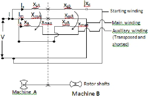
Fig 7- The single phase transfer field reluctance motor with starting windings and capacitor.
Where,
V = Applied voltage, I = Source Current, Im = Main winding Current, Is = Starting winding Current, Ia = Auxiliary winding Current, xmA = Main winding of Machine A. xmB = Main
[image:5.612.327.576.445.611.2]machine A, xsB = Starting winding of machine B, jxC = Capacitive reactance of the starting capacitor (c).
VII/I – Designing for the value of the starting capacitor necessary to place the main and starting winding currents (im/is) in 900 phase shift.
With careful use of the machine parameters of table 1, the main winding impedances (for machine A and B) of fig. 7 can be calculated as below.
Zm(A/B) = ZmA+ZmB ….34
Since ZmA = ZmB = Zm (as xmA = xmB =xm)
⇒ Zm(A/B) = 2zm
= 2(rm+jxm)
…35 By substitution of machine parameters
Zm(A/B) = 2(rm+jxm)
= 2(3+j8.044) =(6+j16.088)
= 17.17∠69.550Ω
Obviously, the main winding current Im lags behind the applied voltage V by 69.550.
Hence Im = 𝑍𝑍 𝑉𝑉 𝑚𝑚(𝐴𝐴/𝐵𝐵) =
220 17.17A∠69.550 = 12.81∠-69.550A
For an efficient design, the starting windings usually have almost the same size of wire and almost as many turns as the main windings. We therefore have that the starting winding impedance for the machine A/B, is
Zs(A/B) =ZsA +ZsB …36
So far ZsA =ZsB = Zs, XsA = XsB = Xs
∴ Zs(A/B) = 2Zs
= 2(rs+jxs) Ω But from the machine parameters of table 1
Zs(A/B) = 2(2.5+j7.544) = (5+j15.088) Ω
Since, time phase angle between starting winding current Is and main winding current Im is 900, so starting winding current Is must lead the applied voltage V by;
φs = 900 - 69.550
= 20.450
If Xc is the capacitive reactance of the capacitor connected in series with the starting winding, then impedance of the starting winding for the two machines A/B, will be given as
Zs(A/B) = (5+j15.088-jXc) = [5+j(15.088-Xc)]Ω
But for starting winding,
Tanφs(A/B) = 15.088−X5 C
⇒ Xc = 15.088 – 5 tan φs (A/B) = 15.088-5tan(-20.45)0 =15.088-(-1.864) =15.088+1.864 =16.952Ω If Xc = 2𝜋𝜋𝜋𝜋𝑎𝑎1
⇒ c = 1
2𝜋𝜋𝜋𝜋 𝑥𝑥𝑎𝑎
= (2x3.142x50x16.952)-1F = 188μF
∴From the above design, the value of the starting capacitor (C ) necessary to place the main and starting winding currents (Im/Is) in quadrature is 188µF.
VIII. SUGGESTED AREAS OF APPLICATION
The transfer field machine in general is a low speed machine operating at half the speed of a normal induction machine (Agu 1978). Single phase motor without rotating windings will have future in a variety or special applications such as very slow speed fixed frequency drives, linear motor for small scale transport systems etc. It is common knowledge that a low speed machine will find application in domestic appliances requiring low speed drives such as grinding machines for perishables. However, many household are invariably supplied with single-phase, necessitating the development of single phase transfer field machine for the purpose of wider applications.
IX. DISCUSSION OF RESULTS/CONCLUSION
This paper has presented the equivalent circuit of a single phase transfer field machine from which the performance indices can be predicted. It may be noted that the torque slip curves due to clockwise, counter clockwise and resultant magnetic fields have been drawn for a slip range of 0.5< s < 1.5. From fig.8c, it is observed that;
a. Net torque Tnet at standstill of the rotor is zero. That is at slip s = 1. The torques developed by the clockwise and counter clockwise fields cancel each other. This is responsible for the non self starting ability of the motor. b. Assuming the rotor is given an initial rotation in any
direction, the net torque developed causes the rotor to continue to rotate in the direction in which it is started c. As a corollary to a, the net torque can also be zero at
some values of rotor speed below the synchronous speed.
Additionally, the machine suffers severe electrical losses which account for its low efficiency when compared to an equivalent single phase induction motor counterpart. This is as a result its excessive leakage reactance. In addition, the intersegment of conductors between the two machine sections contributes to the leakage reactance and does not in any way contribute to energy transfer in the machine.
However, the design analysis for the improvement in the efficiency of the machine is on the pipeline as it is being studied by the authors.
X. ACKNOWLEDGEMENT
REFERENCES
[1] Obute K.C., Anih L.U. and Ezechukwu O.A. (2010) “Steady-State performance analysis of single phase transfer field motor” – A thesis presented to Post Graduate School of Nnamdi Azikiwe University Awka, Anambra State, Nigeria. Pp 1-10, 118-132.
[2] Agu L.A. (1978) “The transfer field Machine, Electric Machine and Electro Mechanics” pp 403-418.
[3] Anih L.U., Obe E.S. and Eleanya M.N. (2015) “Steady-State performance of induction and transfer field motors – A comparison”. Nigeria Journal of Technology (NIJOTECH) Vol 34, No 2 April 2015. Pp. 385- 391.
[4] Jones C.Y. and Prior D.L 1972 “Unification of field and circuit theories of electrical machines” Proc. Of IEE, 119, pp. 871-872.
[6] Stephen J. Chapman (2005) “Electric Machinery Fundamentals” 1221 Avenue Americas New York, Mc. Graw-Hill Inc, NY 10020, Forth edition.
AUTHORS
First Author – Obute K.C, Department of Electrical
Engineering, Nnamdi Azikiwe University Awka, Anambra State, Nigeria
Second Author – Agu V.N, Department of Electrical
Engineering, Nnamdi Azikiwe University Awka, Anambra State, Nigeria
Third Author – Anazia E.A, Department of Electrical
Engineering, Nnamdi Azikiwe University Awka, Anambra State, Nigeria
Fourth Author – Okozi S.O, Department of
Electrical/Electronic Engineering, Federal University of Technology, Owerri, Imo State, Nigeria.
Fifth Author – Anih L.U, 3. Department of Electrical Engineering, University of Nigeria Nsukka, Enugu State, Nigeria
Corresponding Author - Obute Kingsley Chibueze . Department of Electrical Engineering Nnamdi Azikiwe University Awka, Anambra State, Nigeria
Email Address – [email protected]