Abstract- Nowadays there is a huge trend on using timber
roof structure with traditional joineries in hotels
constructions because of its advantages like flexibility,
durability, beautiful appearance, strength, eco-friendly,
energy efficient, and aesthetical freedom. The king post and
beam joinery is one of traditional timber joinery that
commonly used when designing cabanas, summer houses,
greenhouses and lobby in hotels. There is a standard
measurement system is used by carpenters when design a
roof structure and one of the basic measurements is the
distance between two king-post trusses. Generally,
carpenters in Sri Lanka use 8-10 feet as the range for the
distance between two king-post trusses.
In this study, an attempt will be made to investigate the
deflection of a fixed ridge beam due to pressure applied on
the beam and from that to detect the optimum distance
between two king post trusses within the general range and
also find the optimum beam size that can be used to design
the king post beam joinery more effective way. The study is
intended to do analysis on three different types of building
structures; Cabana, Lobby, and Summer house. In this
study, a new model is generated to calculate the deflection
of a fixed beam by using the Euler-Bernoulli Differential
equation and Fourier series. The study is used only clay tiles
as the roof covering materials and Kempas wood as the
material for beams, king posts and rafters.
According to results for the cabana, the optimum distance
between two king post trusses among the general range is 9
feet and the optimum beam size is 2x6 inch2. The optimum
distance between two king-post trusses among the general
range is 8.5 feet and the optimum beam size is 3x6 inch2 for
the lobby. When considering the results for the summer
house, the optimum distance between two king-post trusses
among the considered range is 6.5 feet and the optimum
beam size is 2x6 inch2.
Index Terms- King post, Fixed ridge beam,Euler-Bernoulli
theory, Fourier series
I. INTRODUCTION
The beams are structural elements that resist loads applied
laterally to their axis and they typically transfer loads
imposed along their length to their endpoints where the
loads are transferred to walls, columns, foundations, and so
on. A joint is an area where two separate pieces connect. In timber framing, there are many different types of joints and
connections. Traditional joinery is the classic way to
connect timbers in post & beam and timber frame structures.
The king post and beam joinery are one of traditional
joinery and it is an elegant and beautiful style of
construction.
For this study, the simplest structure of king-post truss used
and king-post and beam joinery connected by using mortise
and tenon. Since both free ends are restrained against
rotation and vertical movement, the ridge beam is a fixed.
II. RESEARCH ELABORATION
Euler-Bernoulli Differential Equation
Euler-Bernoulli Beam theory was developed around 1750 by
Leonhard Euler and Daniel Bernoulli. It is a simple and
effective method to calculate the behavior of beams when a
load is applied.
)
(
1
4
)
(
4
x
q
EI
dx
x
y
d
=
where y(x) - Deflection function. (m)
q(x) - Deflection pressure per unit length at point x(N)
E - Modulus of Elasticity of the beam. (Nm-2)
A Detailed Study on Deflection of Fixed Beams Connected to Three Different
Types of Building Structures due to the Pressure Applied on the Beams
D.S.Rodrigo*, H.M.N.Sewwandi**
*Department of Mathematics, University of Sri Jayewardenepura, Sri Lanka.
www.ijsrp.org I - Moment of inertia of the beam. (m4)
Modulus of Elasticity of wood
The modulus of elasticity is defined as the following
equation.
ε
σ
= E
where ε = Strain (no unit or %)
σ = Stress (MPa)
Its SI unit is the Pascal (Pa) or N/m2 and the practical units
used are Mega-Pascal (MPa or N/mm2) or Giga Pascal (GPa
or kN/mm2).
Moment of inertia of the beam
For this study, the moment of inertia for a rectangular shape
body is used.
Moment of inertia for rectangular shaped body,
I =
12
3
bh
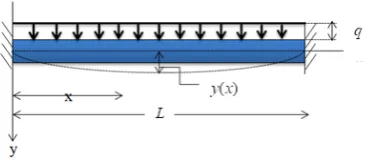
Deflection of a fixed beam under a lateral load
Consider a fixed beam is shown in the following figure 4.1.
It is uniformly loaded by a load
q
per unit length. Thedeflection y(x) of the beam is sought. The axis of the
beam deflects from its initial position under the action of
applied forces.
The function y(x)is satisfied with the differential equation
)
(
1
4
)
(
4
x
q
EI
dx
x
y
d
=
(1)where 1/EI is the rigidity of the beam.
The general expression for y(x)which makes
y
and 𝑑𝑑𝑑𝑑𝑑𝑑𝑑𝑑zero at both ends is
( )
− + − − − + − ∑ ∞ = = L x n n L x L x n L x L x L x n n a xy 1πsin π
2 2 3 3 ) 1 ( 2 2 2 3 3 1 ) (
Assuming the validity of the fourfold by term-by-term
differentiation, obtain =
∑
∞ = L x n L n a dx y d n nπ
π
sin 4 3 3 1 4 4 (2)Then expand q(x)=q into the Fourier sine series
= =
∑
∞ = L x n q q x q n n π sin ) ( 1 (3)where dx
L x n q L q L
n
∫
= 0 sin
2 π n=1, 2, 3…
dx L x n q L q L
n
∫
= 0 sin
2 π =
( )
[
π]
π π π n n q L n L x n L q L cos 1 2 cos 2 0 − = − n
q
= �nπ
q 40
By (1), (2) and (3)
∑
∞ = L x n L n a n n π π sin 4 3 3 1 = ∑
∞ = L x n q EI n n π sin 1 1When n is even, 𝑎𝑎𝑛𝑛= 0 and
when n is odd,
π π n q EI L n
an 4 1 4
3 3 =
b
h
when n is odd
[image:2.595.311.546.399.741.2]when n is even
[image:2.595.54.238.669.749.2]4 4 4 4 π EIn qL an =
Hence + − − − + − − =
∑
∞ = L x n n L x L x L x L x L x a x y n n nπ
π
sin 1 ) 1 ( 2 ) ( 2 2 3 3 2 2 3 3 1 + − =∑
∞∈= + L
x n n L x L x n EI qL x y N i i n π π π sin 1 1 4 ) ( 2 2 1 2 4 4 4 (A)
Maximum Deflection Area Coefficient (MDAC)
In this study, a new coefficient named as Maximum
Deflection Area Coefficient is generated to find the
optimum beam sizes that suitable to build cabana, lobby and
summer house. It is the multiplication of the cross-sectional
surface area of the beam and maximum deflection of the
beam.
A= Cross-sectional surface area
D= Maximum deflection of the beam
Maximum Deflection AreaCoefficient =
A
×
D
Here optimum size beam introduced as the beam which has
the lowest value for Maximum Deflection Area Coefficient.
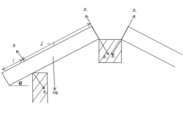
Following reactions are considered for all building structures.
Reaction on the beam by rafter
Following symbols are represented different reactions types
of the roof structures.
−
R
The reaction on wall beam by a rafter,R
1−
Thereaction on beam by rafter,l− Length of the eave, N −
Number of rafters in one side of the beam,
q
1−
Thereaction on the beam per unit length by rafter,
q
2–Theweight of the beam per unit length,
q
3−
The reaction on the beam per unit length by support.The moment around the wall beam
(
)
−
×
×
=
−
×
L
l
M
L
l
R
2
cos
1θ
l
L
l
L
M
R
−
−
×
×
=
2
cos
1θ
The downward reaction on the beam by rafters=
×
=
×
×
=
2
1cos
2
3
R
θ
R
(
)
l
L
l
L
M
−
−
×
×
2
cos
θ
2The reaction on the beam per unit length by rafter,
q
1=
(
)
−
−
×
×
×
37
.
39
2
2
cos
2
2l
L
l
L
M
θ
The weight of the beam per unit length =
D W q2 =
Reaction on the beam by king post
The total reaction on the beam by both rafters and king
[image:3.595.319.495.544.686.2]posts=
×
+
=
2
3 2W
R
N
R
Figure 3: A roof structure [image:3.595.41.226.558.673.2]The reaction on the beam per unit length by support =
37
.
39
3
2
3
=
×
R
q
Following measurements are used for each building
structures to obtain final results.
Table I: Measurements of all building structures
The
building
type
The
length of
the
beam(m) The
number
of rafters The
number
of king
post
trusses
The angle
between
beam and
rafter
Cabana 5.03 11 2 39.810
Lobby 10.01 21 4 39.810
Summer
house
2.54 6 2 36.870
The selected region for the distance between two king post
trusses of the cabana and the lobby is 7.5-10.5 feet and since
the summer house is a small scale size of the building then
the selected region for the distance between two king post
trusses is 4.5-7 feet.
III. RESULTS
The MATLAB software is used to obtain the following
results. In this study, the optimum distance between two
king post trusses among the general range is obtained
directly by using the minimum deflection value for each
beam size. The optimum beam size is obtained by using a
new coefficient named as Maximum Deflection Area
Coefficient. The beam which has a minimum coefficient
value is taken as the optimum beam size. All results are
obtained by using Kempas wood for roof structures.
Table II, III, and IV are depicted the maximum deflection of
the beam for all type of building that has different beam
sizes and different distance between two king-post trusses.
Table V is showed the Maximum Deflection Area
Coefficient for all building structures.
Table II: The maximum deflection of the beam for the
cabana
Type of building
The Cross- sectional surface area of the beam
(inch2)
The distance between two king post trusses
( feet)
The maximum deflection of
the beam (meter)
Cabana 2x4 7.5 0.0056
8 0.0039 8.5 0.0022 9 0.000303 9.5 0.0017
10 0.0037 10.5 0.0059
2x5 7.5 0.0029
8 0.002
8.5 0.0011 9 0.0001619 9.5 0.0008586 10 0.0019 10.5 0.0031
2x6 7.5 0.0017
8 0.0012 8.5 0.0006645
9 0.00009824 9.5 0.0004995
10 0.0011 10.5 0.0018
3x4 7.5 0.0038
8 0.0027 8.5 0.0015 9 0.0002213 9.5 0.0011
10 0.0025 10.5 0.004
3x5 7.5 0.002
8 0.0014 8.5 0.0007872
9 0.000121 9.5 0.0005823
10 0.0013 10.5 0.0021
3x6 7.5 0.0012
Table III: The maximum deflection of the beam for the
lobby
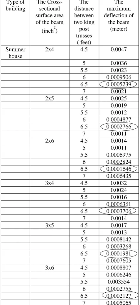
Table IV: The maximum deflection of the beam for the
summer house
Type of building
The Cross- sectional surface area of the beam
(inch2)
The distance between two king post trusses
( feet)
The maximum deflection of
the beam (meter)
Summer house
2x4 4.5 0.0047
5 0.0036 5.5 0.0023 6 0.0009506 6.5 0.0005239 7 0.0021
2x5 4.5 0.0025
5 0.0019 5.5 0.0012 6 0.0004877 6.5 0.0002766 7 0.0011
2x6 4.5 0.0014
5 0.0011 5.5 0.0006975
6 0.0002824 6.5 0.0001646 7 0.0006435
3x4 4.5 0.0032
5 0.0024 5.5 0.0016 6 0.0006361 6.5 0.0003706 7 0.0014
3x5 4.5 0.0017
5 0.0013 5.5 0.0008142
6 0.0003268 6.5 0.0001981 7 0.0007605 3x6 4.5 0.0008807 5 0.0006246 5.5 0.003554
6 0.0002755 6.5 0.0002127 7 0.0005065 Type of
building
The Cross- sectional surface area of the beam
(inch2)
The distance between two king
post trusses
( feet)
The maximum deflection of
the beam (meter)
Lobby 2x4 7.5 0.0985
8 0.0545 8.5 0.0078 9 0.0417 9.5 0.0939 10 0.1489 10.5 0.2066
2x5 7.5 0.0508
8 0.0281 8.5 0.0039 9 0.0217 9.5 0.0488 10 0.0772 10.5 0.1071
2x6 7.5 0.0564
8 0.0310 8.5 0.0041 9 0.0244 9.5 0.0545 10 0.0862 10.5 0.1190
3x4 7.5 0.0666
8 0.0367 8.5 0.0049 9 0.0288 9.5 0.0644 10 0.1018 10.5 0.1410
3x5 7.5 0.0345
8 0.0189 8.5 0.0023 9 0.0152 9.5 0.0337 10 0.0531 10.5 0.0735
3x6 7.5 0.0201
Table V: Maximum Deflection area Coefficient for all building structures
IV. CONCLUSIONS
According to results, the optimum distance between two
king post trusses among the general range is 9 feet, 8.5 feet
and 6.5 feet for cabana, lobby and summer house
respectively. According to Table V, the optimum size of the
beam for cabana is 2x6 inch2, for lobby is 3x6 inch2 and for
summer house is 2x6 inch2.
All the results are obtained by considering the deflection
values of the beam under some limitations from the practical
situation. Following limitations are used for the study.: The
beam is homogeneous material that has the same modulus of
elasticity in tension and compression, The cross-sectional
surface area of the beam is uniform, The beams are
rectangular timber beams and it has a longitudinal plane of
symmetry, Any section of a beam that is a flat plane before
the beam deforms will remain a flat plane after the beam
deforms, Any section of a beam that is perpendicular to the
neutral axis before the beam deforms will remain
perpendicular to the neutral axis after the beam deforms,
The roof covering material here used only clay tiles, In this
study based on fixed supported beam structure that has only
beams king posts and rafters, Only consider the weights of
beams, rafters and clay tiles.
REFERENCES
[1] B. F. Ruffner, The Use of Fourier Series in the Solution of Beam Problem, Oregon State Engineering Experiment Station, Oregon, , 1944.
[2] T. Sakai, Solution of Problems of Applied Mechanics by Fourier Transformation Method, viewed 29 January 2018, 1952,
https://eprints.lib.hokudai.ac.jp/dspace/bitstream/2115/37771/1/9(2)_ 133-190.pdf.
[3] D. A. Thatrigoda, & D. S. Rodrigo, Numerical Implementation of Fourier Transforms and Associated Problems, International Journal of Multidisciplinary Studies, vol.1, 2014.
[4] D. S. Rodrigo & H. M. N. Sewwandi, ‘Analysis of Deflection of a Fixed Ridge Beam due to Pressure Applied on the Beam’, International Journal of Engineering and Applied Sciences(IJEAS), vol.5, pp.24-28, viewed 04 August 2018, https://www.ijeas.org/IJEAS0506009
[5] D. S. Rodrigo & H. M. N. Sewwandi, ‘Comparison of Deflection Patterns of Simply Supported and Fixed Supported Beam Structures’, International Journal of Advanced Engineering Research and Science (IJAERS), Vol -5, Issue-9, Sept- 2018, https://dx.doi.org/10.22161/ijaers.5.9.26
Type of the building structure
The cross-sectional surface area of the
beam (inch2)
The maximum deflection of the beam
(inch)
Maximum Deflection Area
Coefficient (inch3)
Cabana 2x4 0.0012 0.0096 2x5 0.0064 0.0640 2x6 0.0039 0.0468 3x4 0.0087 0.1044 3x5 0.0048 0.0720 3x6 0.0029 0.0522
Lobby 2x4 0.3079 2.4632
2x5 0.1535 1.5350 2x6 0.1614 1.9368 3x4 0.1929 2.3148 3x5 0.0906 1.3590 3x6 0.0512 0.9216 Summer
house
2x4 0.0109 0.0872