Li-Fi Technology and its Application in Wireless
Sensor Network
Ms. Surekha N. Shelke1, Mr. A. P. Kiranagi 2, Mr. A. S. Patel3
1,
M.E scholar,2Asst. Prof, 3H.O.D, Department of Electronics and Telecommunication, MSS College of Engineering and Technology. Jalna (MS), (India)
Abstract: Li-Fi means Light-Fidelity. Li-Fi technology, proposed by the German Scientist Harald Haas, Harald Haas proposed the technology .In this paper design and implementation of Li-Fi technology for wireless sensor network is presented. The wireless sensor node is designed to sense temperature and fire. Whereas Li-Fi is ideal for high density wireless data coverage in confined area and especially useful for applications in areas where radio interference issues are of concern, so the two technologies can be considered complimentary.
Keywords: Light Emitting Diode (LED), Light-Fidelity (Li-Fi), Visible Light Communication (VLC), Wireless-Fidelity (Wi-Fi), Wireless Sensor Network (WSN).
I. INTRODUCTION
In today’s Digital world we have electromagnetic wave in almost all networks. Li-fi is new technology that can be used to transfer of data from one end to other end wirelessly. Li-Fi has got a much broader spectrum for transmission compared to conventional methods of wireless communications that rely on radio waves. The basic ideology behind the technology is somewhat similar to fiber optic communication. At one end light source is use to transfer the data by switching light on and off. The light on off human eye doesn’t notice, because of high switching speed of light.
II. RELATED WORK
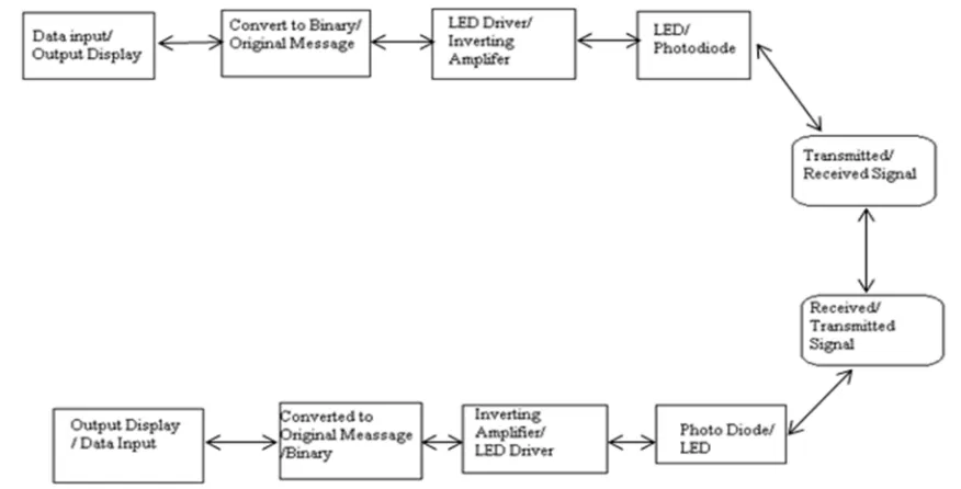
[image:2.612.90.528.493.716.2]The aim of this paper is to design and develop Li-Fi for wireless sensor network by exploring the advantages and limitations of existing work. Bharath B and Yaswanth Digumarthi [1] has proposed the Li Fi system “BIDIRECTIONAL COMMUNICATION IN LI-FI TECHNOLOGY” they have implemented it as shown in block diagram fig 1. In transmitter section, the input data is converted into binary information which is given to LED driver. It drives the binary information to the high illumination LED. In the receiver section, the photo detector receives the binary information and amplifies it using inverting amplifier. The original message is then obtained in the output display.
Alao O.D. [3] has given valuable explanation in paper ‘Light Fidelity (Li-Fi): An Emerging Technology for The Future about limitations of Li-fi’. These are as follow
A. You cannot dim the light
B. You need special LED
C. The main problem is that light can‘t pass through objects, so if the receiver is inadvertently blocked in anyway, then the signal will immediately cut out. If the light signal is blocked, or when you need to use your device to send information you can seamlessly switch back over to radio waves.
D. According to Harald, Reliability and network coverage are the major issues to be considered by the companies while providing
VLC services. Interference from external light sources like sun light, normal bulbs; and opaque materials in the path of transmission will cause interruption in the communication.
E. High installation cost of the VLC systems can be complemented by large-scale implementation of VLC though Adopting VLC
technology will reduce further operating costs like electricity charges, maintenance charges etc.
III. SYSTEM OVERVIEW
[image:3.612.149.464.404.517.2]The main part of Wireless sensor network is Wireless nodes and second is monitoring unit. In this system we used Li-Fi for communication between nodes and monitoring unit because of its benefits over existing radio wave. As shown in fig.3 the Li-Fi sensor node will consist of sensor, microcontroller, Li- Fi wireless connectivity. The main part here is Li- Fi circuitry and its operation. The operating principle used in the system is same as other Li-Fi system with some of the modifications. We used LDR instead of photodiode to sense the light status on and off. Output voltage of photodiode with respect to light intensity is not linear. We used the LDR to sense the existing light intensity present in the working area. This will be the threshold value for normally on status of light. As the light intensity decrease below preset threshold value microcontroller detect it as light source off condition. This way data sent to receiver. The light source will continuously on in this system. During data transfer light source starts blinking. The system block diagram is as shown in fig2.
Fig 2 Li-Fi based Wireless Sensor Node
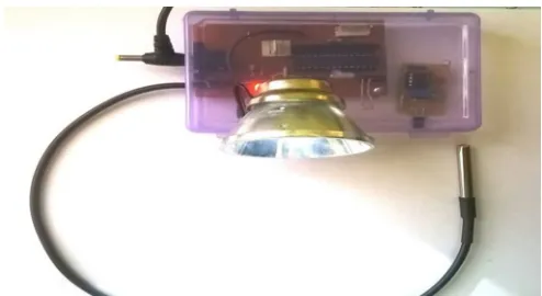
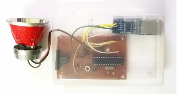
The Sensor node implemented is as shown in fig 3. It consists of Atmega328 microcontroller, LED light source, Fire sensor module and DS18b20 temperature sensor.
[image:3.612.182.429.587.722.2]At receiver end data received is fed to LAN network using ethernet module ENC28J60. So sensor data is visible to all users within network using web browser. The implemented circuit is as shown in fig 4.
Fig 4 Li-Fi based web server node
IV. RESULTS
[image:4.612.111.503.386.520.2]The system tested by operating it within room with minimal light intensity. As receiving node can measure variation in light intensity we don’t need complete dark room. Only requirement is that light source should have light intensity 20 % greater than normal room light intensity. The test set up for experimentation was as shown in fig 5. The 3w LED light source used here and distance between nodes is about 1.5 meter. The test system was in room during day time. Room is not confined has lower light intensity than LED. Remote node sends the parameter temperature, fire using LED to receiver node. As the receiver node is interfaced with ethernet module ENC28J60 using LAN connection remote temperature and fire status available on PC/Laptop.
Fig.5 Implemented working model of Li-Fi
Just we need to enter the IP address in web browser. The result display in web page showing temperature and fire status as shown in fig. 6
A. Features of the system
1) Range: Depends upon how far light Source intensity obtain 20% greater than normal condition
2) Fire detection range: 1 meter
3) Fire sensor wavelength: 760nm to 1100nm
4) Operating Speed: 10 Mbps
5) Temp. Sensing range: -55 to 125 degree
6) Sensor attached: Temp. Sensor DS18b20, Fire detection sensor IR
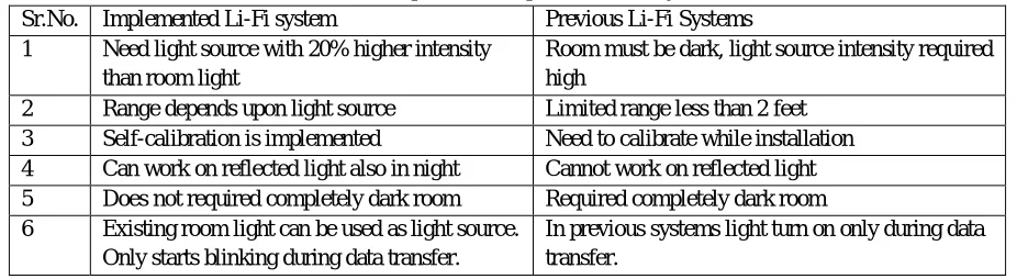
[image:5.612.75.538.217.344.2]B. The comparison of this system with previous work is as follow
Table 1 Comparison with previous Li-Fi system
Sr.No. Implemented Li-Fi system Previous Li-Fi Systems
1 Need light source with 20% higher intensity
than room light
Room must be dark, light source intensity required high
2 Range depends upon light source Limited range less than 2 feet
3 Self-calibration is implemented Need to calibrate while installation
4 Can work on reflected light also in night Cannot work on reflected light
5 Does not required completely dark room Required completely dark room
6 Existing room light can be used as light source.
Only starts blinking during data transfer.
In previous systems light turn on only during data transfer.
V. CONCLUSION
This paper presents the application of Li-Fi in Wireless sensor network. Li-Fi can be used in room during daylight, only needs light source whose light intensity should have greater than normal room light intensity. Implemented system can also work on reflected light. This system overcomes limitation of Li-Fi which is requirement of confided room. The future development required in this design is that extending the communication point to multipoint. Li-Fi Sensor network is best if some of the limitations that are discus in this paper are overcome. If WSN network is in industrial area where already very large electromagnetic interference is present in such place LI- Fi can be best choice. In hospitals and EMF radio wave restricted area Li-Fi Sensor network is can be applicable.
REFERENCES
[1] Bharath B., Yaswanth Digumarthi ,BIDIRECTIONAL COMMUNICATION IN LI-FI TECHNOLOGY, VOL. 11, NO. 13, JULY 2016, ISSN 1819-6608 . [2] Rahul R. Sharma, Raunak, Akshay Sanganal, Li-Fi Technology Transmission of data through light, Vol 5 (1),150-154 ISSN:2229-6093
[3] Alao O.D., Joshua J.V., Light Fidelity (Li-Fi): An Emerging Technology for The Future, Volume 3, Issue 3. (May. - Jun. 2016),e-ISSN: 2394-0050, P-ISSN: 2394-0042.
[4] Mr. Korde S. K, Review Paper on Li-Fi (Light Fidelity), Vol-2 Issue-3 2016,IJARIIE-ISSN(O)-2395-4396
[5] Kiran Maraiya and Kamal Kant, Application based Study on Wireless Sensor Network, Volume 21– No.8, May 2011, International Journal of Computer Applications (0975 – 8887)
[6] Rahul R. Sharma, Raunak, Akshay Sanganal, Implementation of A Simple Li-Fi Based System, Volume 1, Issue 9, October 2014, ISSN : 2348 – 6090 [7] T.Kavitha, Programmable Irrigation Control System Using Li-Fi, Vol. 4, Special Issue 6, May 2015, ISSN(Online) : 2319 – 8753 ISSN (Print) : 2347 – 6710 [8] Ullas Chandran, Implementation of Li-Fi Technology for Home Automation and Vehicle Communication, Vol 2 Issue 10 April 2016, ISSN (online):
2349-784X
[9] Vitthal S Saptasagare, Next of Wi-Fi an Future Technology in Wireless Networking Li-Fi Using Led Over Internet of Things, Volume-3, Issue-3March 2014, ISSN: 2278-9359.
[10] Dr. Deepti Gupta, Wireless Sensor Networks ‘Future trends and Latest Research Challenges’, Volume 10, Issue 2, Ver. II (Mar - Apr.2015), e-ISSN: 2278-2834,p- ISSN: 2278-8735.
[11] Mrs. P. Eswari, A Real Time Application of Li-Fi Technology in Wireless Communication System, Vol. 3, Issue 3, March 2016, ISSN 2394-3777 (Print) ISSN 2394-3785 (Online).