2018 2nd International Conference on Applied Mathematics, Modeling and Simulation (AMMS 2018) ISBN: 978-1-60595-580-3
A Novel Calibration Method Based on Vanishing Points and Lines for
Linear Structured Light Vision Sensor
Yan LIU, Dong WU, Wei-ran LI, and Shu-wen PAN
*School of Information and Electrical Engineering, Zhejiang University City College, Hangzhou, China
*Corresponding author
Keywords: Linear structured light vision sensor, Vanishing points, Vanishing lines, Light plane calibration.
Abstract. To meet the requirements of our own laboratory, the calibration method of linear structured light vision sensor based on the vanishing points and the vanihing lines is proposed. The concentric circles with a set of orthogonal diameters and known distance are designed as targets to calibrate the camera and linear structured light projector. Firstly, the orthogonal characteristics of the two vanishing points on orthogonal diameters are used to calibrate the internal and external parameters of the camera. Then the relationship between the normal vector of plane and the parameters in camera is applied to calibrate the normal vector of light plane. Finally, the forth parameter of light plane is obtained by using the coordinates of the known points in the target coordinate system. The experimental results show that the measurement average relative error of the sensor is 0.17%. It is proved that the linear structured light vision sensor with high accuracy and this is a feasible proposed calibration method.
Introduction
Structured light three-dimensional measurement is an attractive area in computer vision. Potential applications are in the domains of product quality inspection, reverse engineering, 3D printing. The linear structured light vision sensor consisted of a projector and a camera has been widely used for its advantages of simple structure, easy modeling, and high precision [1].
The linear structured light vision sensor based on the triangulation measurement principle must be modeled and calibrated before it can be used. Many scholars have done a lot of research on these areas. According to the method to determine the plane equation coefficients, the existing calibration technique can be divided into the following two categories: (1) obtaining light plane parameters by fitting calibration points; (2) Two-step method: firstly, determine the normal vector; secondly, calculate the forth parameter [2,3]. Most calibration methods fall into the first category.
For the first class of calibration methods, according to their way to the dimension of the target, which can be classified into three types: 3D target, 2D target and 1D target. Self-generated target method [4], jugged target method [5], cross-ratio invariance of three-dimensional target [6] and ball target [7,8] are belong to the methods based on 3D target. These methods need precision calibration auxiliary facilities, the calculation process is complicate, or the image process is complicate. To solve these problems, some methods with the 2D target are proposed [ 9,10]. As for these methods, the calibration targets’ production is simple, and they are suitable for field calibration, but these methods need to establish the local coordinate and to carry out the coordinate transformation many times. To further simplify the calibration procedure, the calibration method based on o1D target was proposed. This method is mainly based on collinear point for plane equation parameters solution [11-13]. These kinds method provide few calibration points, which will decrease the precision of the calibration or increase more moving times of the target in the field of the camera view.
we design the concentric circles with a set of orthogonal diameters and known distance on a plane as the calibration target. We propose a novel 2D target-based calibration method for structured light vision sensors using the vanishing points and lines by randomly viewing the target from different unknown orientations positioned within the field of view. This method can calibration the camera and the light plane. Firstly, the orthogonal characteristics of the two vanishing points are used to calibrate the internal and external parameters of the camera. Then the relationship between the normal vector of plane and the parameters in camera is applied to calibrate the normal vector of light plane. Finally, the optical plane constant term is obtained by using the coordinates of the known points in the target coordinate system.
Measurement Model of Linear Structured Light Vision Sensor
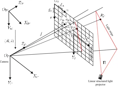
Linear structured light vision sensor consists of a camera and a linear structured light projector, and their relative position between them is fixed, once the system is established. The measurement model of linear structured light vision sensor is shown in Fig.1. The calibration includes camera calibration and the light plane calibration.
Linear structured light projector Camera
Im
a
g
e
p
la
n
e
Lig ht s
[image:2.595.202.411.299.452.2]tripe
Figure 1. The measurement model of linear structured light vision sensor.
Camera Model
Camera is described by the pinhole model on condition that its lens’ aberration is insignificant. Camera calibration is to determine the camera model’s intrinsic parameters and extrinsic parameters. The intrinsic parameters are given by
, . (1)
Where is the transformation matrix between pixel coordinates and the normalized
coordinates of a point. Its elements of and are the scale factors in pixel image and axes,
and is the parameter describing the skew of the two image axes(for square pixels, is zero), and its
elements , are pixels coordinates of the principal point, which can be seen in Fig.1.
The extrinsic parameters represent the position and orientations of the camera relative to the world coordinate system is given by
The top 3×3 corner and 3×1 vector describe the orientation and the translation of the camera relative to the world coordinate system, respectively. They can be also shown in Fig.1.
For cameras with negligible lens distortion, , , , are parameters to be calibrated.
The Linear Structured Light Projector Model
The linear structured light projector projects a laser beam, which is contained in a plane. So the light beam can be expressed by a space plane equation.
. (3)
, , are any real number and the vector are the normal vector of the light plane. It is known that if the sensing system does work the laser light beam cannot pass through the origin of the camera coordinate system, so can be chosen as any real number except zero. The linear structured light projector calibration is to get the plane equation coefficients.
Camera Calibration
Camera Intrinsic Parameters Calibration
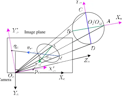
Taking a circle with a set of orthogonal diameters as the calibration target, its image is shown in Fig.2. AB and CD are the set of orthogonal diameters of the circle in the world coordinate system. pc and qc
are the vanishing points of AB and CD, respectively. According to the knowledge of projective geometry [14]and the properties of rigid body, the fact that the vectors Ocpc and Ocqc are always
orthogonal can be obtained. So, the triangle Ocpcqc is a right-a
Camera
[image:3.595.197.406.416.580.2]Image plane
Figure 2. The calibration target imaging process for extrinsic parameters.
For the right-angled triangle, the Pythagorean Theorem provides a useful fact:
. (4)
Set and are the
coordinates of pc and qc in the camera coordinate system, respectively.
and are their focal length normalized
coordinates, respectively. Substitute them into Eq. 4, we get
The Eq. 5 contains u0, v0, , , which are the camera intrinsic parameters. , , and ,
can be calculated by the harmonic conjugate theory.
Eq. 5 is a non-linear equation about the camera intrinsic parameters. To obtain the camera intrinsic parameters linearly, take n images of the target by the camera and calculate the coordinates of the vanishing points, then get n equations about the intrinsic parameters, use the ith equation of Eq. 5 subtracts the jth (1≤i, j ≤n, j≠i) of Eq. 5, we have
. (6)
That is
. (7)
Set , , , when n≥4, we get n-1 linear equations with , , .
. (8)
Write it as a matrix equation
. (9) Using the least square method, we can get
. (10)
The solutions , , are obtained. Substitute them into the Eq. 7, according
to the practical significance of the parameters, so the solution , can be calculated as
(11)
Camera Extrinsic Parameters Calibration
Let be a 3D coordinate frame, whose orientation is in coincidence with the world coordinate frame and whose coordinate origin coincide with the original point of the camera coordinate frame, the dotted line indicated coordinate frame as shown in Fig.3. According to the characteristics of the vanishing points, the vector Ocpc and Ocqc are parallel with the OwXw and OwYw
axes of OwXwYwZw, therefore, the vanishing points p and q lies on the OwXw’ and OwYw’ axes of
OcXw’Yw’Zw’, and OcZw’ can be get from Right-handed Rule.
Owing to the camera has been calibrated, the normalization of focal length coordinates of the
vanishing points p and q are known as and ,
respectively. Since that the vanishing points p and q have been determined, the following simple procedure shows how to calibrate the camera extrinsic parameters:
(1) computer, and normalize to unit length, the normal vector n = (n1, n2, n3)T of Ocpcqc plane using
the two computed vanishing points p and q:
. (13)
(2) computer the angle ηbetween n and the Zc = (0, 0, 1)T of OcXcYcZc:
. (14)
(3) computer, and normalize to unit length, the normal vector δthat is orthogonal to n and the Zc = (0, 0, 1)T of OcXcYcZc :
(15)
(4) computer the rotation matrix R that brings Zc to align with n. It can be perceived form Fig.3 that
a rotation of angle ηabout an axis passing through the origin and parallel to δwould do the job. The matrix for this rotation can be derived from Rodrigues formula. So, Define
(16)
where I is the 3 × 3 identity matrix and I × is the skew-symmetric matrix formed by . If n and
Zc are parallel then =0, and R=I.
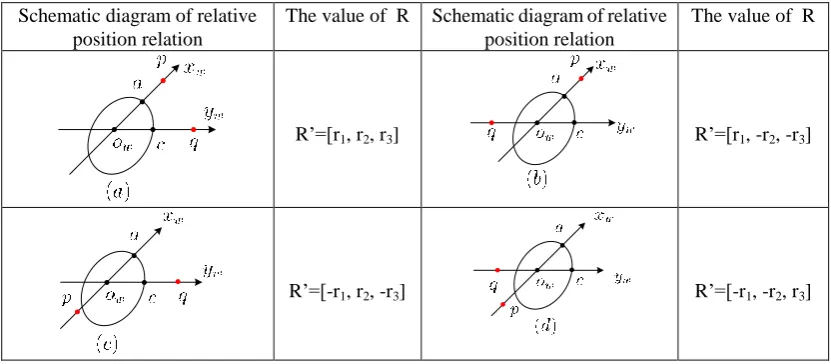
The position of the vanishing points p and q are uncertain relative to the axes image owxw and owyw
of the world frame OwXwYwZw. Set R=[r1, r2, r3], there are four possibilities of the relative position
Table 1. Four possible relative position between the vanishing points p, q and the axes image owxw and owyw.
Schematic diagram of relative position relation
The value of R Schematic diagram of relative position relation
The value of R
R’=[r1, r2, r3] R’=[r1, -r2, -r3]
R’=[-r1, r2, -r3] R’=[-r1, -r2, r3]
According to the combination of point and line in projective geometry and the establishment of world coordinate frame, we can use the cosine of the angle between the vector and , which are the image of the OwXw and OwYw axes of world coordinate frame. We obtain
. (17)
Due to the error of camera calibration and image noise, the rotation matrix obtained by the above process can not satisfy the unit orthogonality. We need to solve the optimal estimation based on the known matrix. According to [15], we can do singular value decomposition for the known matrix first,
. (18) According to the solution criteria,
. (19)
Then the most optimal solution can be calculated to be
. (20) That is the rotation matrix of the camera extrinsic parameters.
Translation vector is the coordinates of the world coordinate frame origin in the camera coordinate
frame. That is .
Structured Light Plane Calibration
Our calibration method based on the planar target can be carried out by two steps. Firstly, calculate the normal vector nL of the light plane using the vanishing points and vanishing line of the light plane;
Secondly, determine the parameter d of the light plane using the points in the target pattern.
Computer the Normal Vector of the Light Plane
Vanishing line l of a plane in 3D space is determined by its normal vector nl, and the following
. (21) where K is the intrinsic parameter matrix of the camera, and L stands for the direction of vanishing line l in 2D image.
By Eq. 18, we can see that if the vanishing line l of the light plane in the image has been obtained, the normal vector nl of the light plane is determined.
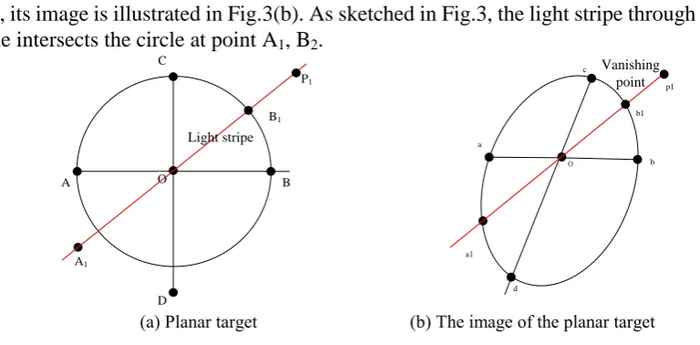
Using the calibration target shown in the above section, its geometric characteristics is illustrated in Fig.3. The light stripe that do fall onto the center O of the circle on the target plane is shown in Fig.3(a), its image is illustrated in Fig.3(b). As sketched in Fig.3, the light stripe through the center of the circle intersects the circle at point A1, B2.
B A D C O A1 B1 Light stripe P1 d b a c a1 b1 p1 o Vanishing point
(a) Planar target (b) The image of the planar target
Figure 3. The Geometric property of planar target projection.
Since O is the center of the circle and it is also the midpoint of A1B1. P1 is a point at infinity. We can
also say A1, B1 harmonically conjugate with respect to points that points O, C1. Suppose the
corresponding image points of A1, B1, O, P1 are a1, b1, o, p1, respectively, and since both collinearity
and cross-ratio are projective invariants, we may easily conclude that a1, b1, o, p1, are also collinear
and their cross-ratio is kept as -1. Based on these two properties, we obtain the following two equations:
. (22)
p1 can be easily solved through the above two equations.
In the field of view of the camera, the position of the plane target is changed for many times under the condition that the light stripe passes through the center of the circle. According to the above process, the vanishing point pi (i=1……n, n≥2) of each different light stripe line can be calculated.
The equation of the vanishing line of the light plane is obtained by fitting all the vanishing points. K and nl are known, and plug them in Eq. 18, the normal vector of the light plane can figured out.
Computer Parameter d of the Light Plane
Using the points known coordinates in the planar target and the relative position between the camera and the target, the parameter d can be determined. To ensure the accuracy of calculation, several points can be selected for calculation.
Physical Experiment
[image:7.595.95.479.174.363.2][image:8.595.103.483.85.268.2]
(a) The planar target (b) The linear structured light vision sensor Figure 4. Calibration equipment.
Calibration Results
The system calibration process is as follow:
(1) Capture images of the planar target 20 different positions within the measurement range of camera. Extract the pixel coordinates of the center, the intersections of the two diameters and each circle. Calibrate the internal parameters of the camera by the principle described in camera intrinsic parameters section. The calibration results are as follow:
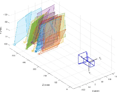
(2) When the target position changes, the external parameters of the camera also change. According to the method of solving the external parameters of the camera introduced in camera extrinsic parameters section, the external parameters of the camera of 20 positions can be obtained. The target positions can be shown in matlab as Fig.5.
Figure 5. Schematic diagram of target locations.
Image Plane Calibration Results
Capture images of light stripe on the planar target cross the Center of the circle at 20 positions within the measurement range of the camera. Extract the pixel coordinates of the of the center, the intersections of the two diameters and each circle. Using the method described in light plane normal
[image:8.595.191.423.495.678.2]After the initial value of the normal vector is known, the fourth parameter d can be obtained by the method described in the part of d calibration, and d=2777.78.
Therefore, the light plane equation in the target coordinate system is 0.0656x+135.7631y+22.6517z+2777.78=0.
Accuracy Evaluation
Use the Zhang’s method[14] to calibrate the intrinsic parameters, and the results are as follows:
Use the above camera parameters and the light plane calibrate method, the light plane equation is 0.0712x+135.9876y+21.9989z+2778.96=0.
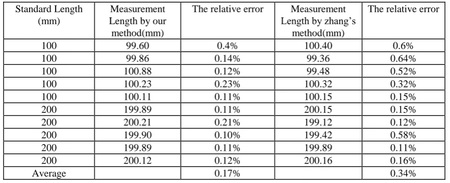
[image:9.595.78.519.299.478.2]Apply the above two sets of data to measure two segment 100mm and 200mm, respectively. The measurement results show in Table 2.
Table 2. The results of the measurement using different method.
Standard Length (mm)
Measurement Length by our method(mm)
The relative error Measurement Length by zhang’s
method(mm)
The relative error
100 99.60 0.4% 100.40 0.6%
100 99.86 0.14% 99.36 0.64%
100 100.88 0.12% 99.48 0.52%
100 100.23 0.23% 100.32 0.32%
100 100.11 0.11% 100.15 0.15%
200 199.89 0.11% 200.15 0.15%
200 200.21 0.21% 199.12 0.12%
200 199.90 0.10% 199.42 0.58%
200 199.89 0.11% 199.89 0.11%
200 200.12 0.12% 200.16 0.16%
Average 0.17% 0.34%
From the measurement Table 2, we can see the method proposed in this method’s have the more accurate measurement results.
Summary
A novel sensor for a linear structured light vision sensor is proposed in this paper. The presented method is used a planar target with concentric circles, which have a set of orthogonal diameters and relative distances and radius are known. The vanishing points on the diameters are applied to calibrate the intrinsic and extrinsic parameters of the camera, and the vanishing lines is used to calibrate the normal vector of the light plane. Here, the forth parameter of the light plane is use the camera extrinsic parameters and the known coordinates in the target. The method proposed in this paper is less difficult than the three-dimensional calibration methods and part two-dimensional calibration methods, and more difficult than the one-dimensional calibration methods. The experimental results show that the average relative measurement error of the proposed sensor is 0.17%. The further test experiment should be done to verify the effectiveness of the method.
Acknowledgements
References
[1] Kaihua Wu, Wenjie Wang, Detection method of obstacle f or plant protection UAV based on structured light vision, Opto-Electronic Engineering, 4, 27-35, 2018.
[2] Tianfei Chen, Jibin Zhao, Xiang Wu, New calibration method for line structured light sensor based on planar target, Acta Optical Sinica, 35(1), 1-9 (2015).
[3] Zhenzhong Wei, Meng Xie, Calibration method for line structured light vision sensor based on vanish points and lines, International Conference on Pattern Recognition, 794-797(2010).
[4] R. Dewar, Self-generated targets for spatial calibration of structured light optical section sensors with respect to an external coordinate system, Robots and Vision’s88 Conf, 5-13(1988).
[5] F. J. Duan, F. M. Liu, Sh. H. Ye, A new accurate method for the calibration of line structured light sensor, Chinese Journal of Scientific Instrument, 12(1), 108-110(2000).
[6] G. Y. Xu, L. F. Liu, J. C. Zeng, et al., A new method of calibration in 3D vision system based on structure-light, Chinese Journal of Computers, 81(6), 450-456 (1995).
[7] Jing Xu, Jules Douet, Jianguo Zhao, Libin Song, Ken Chen, A simple calibration method for structured light-based 3D profile measurement, Optics & Laser Technology, 48, 187-193(2013).
[8] Zhen Liu, Xiaojing Li, Fengjiao Li, Guangjun Zhang, Calibration method for line-structured light vision sensor based on a single ball target, Optics & Laser Technology, 69, 20-28(2015).
[9] F. Q. Zhou, G. J. Zhang, Facilitated method to calibration model parameters of vision sensor for surface measurement, Chinese Journal of Mechanical Engineering, 41, 175-179 (2005).
[10] W. Gao, L. Wang, Z. Y. Hu, Flexible calibration of a portable structured light system through surface plane, Acta Automatica Sinica, 3, 1358-1362(2004).
[11] J. D. Han, N. G. LV, M. L. Dong, Fast method to calibration structure parameters of line structured light vision sensor, Opt. Precision Eng, 17, 958-963 (2009).
[12] Zhenzhong Wei, Lijun Cao, Guangjun Zhang, A novel 1D target-based calibration method with unknown orientation for structured light vision sensor, Optics & Laser Technology, 42, 570-574(2010).
[13] Yan Liu, Qinglin Wang, Yuan Li, Jinhua She, A calibration method for a linear structured light system with three collinear points, International Journal of Computational Intelligence Systems, 4, 1298-1306(2011).
[14] Hartley R. Multiple view geometry in computer vision [M]. London: Cambridge University Press, (2003).