2018 International Conference on Computer, Communications and Mechatronics Engineering (CCME 2018) ISBN: 978-1-60595-611-4
A Computer-Experimental Approach to Modeling the Machine Tool
Dynamics Including the Effect of Spindle Bearing Preload
Wei-zhu LIN, Kun-da WU, Wei-cheng SHIH and Jui-pin HUNG*
Graduate Institute of Precision Manufacturing, National Chin-Yi University of Technology, Taichung 41170, Taiwan, R.O.C.
*Corresponding author
Keywords: Bearing preload, Dynamic compliance, Machining stability.
Abstract. Machining performance of a milling machine is greatly affected by the frequency response function of the spindle tool. Investigation of the preload effect of the spindle bearing on the dynamic performance is of importance for design improvement of the milling machine. This study was therefore aimed to assess the dynamic characteristics of a milling machine by experimental and finite element approaches. To this end, the finite element model of a milling system was created for dynamic analysis. The milling system was composed of a vertical column structure, spindle tool module, and feeding mechanism of the spindle head stock, in which the rolling interfaces in linear components such as bearing and rolling guide were simulated by using surface to surface contact element at the raceways. To ensure the prediction accuracy, the spindle model was experimentally validated by conducting vibration tests on a physical spindle unit and then the frequency responses of milling system with different spindle bearing preload were predicted by harmonic analysis. Current results clearly show that the bearing preload directly affects the tool end frequency response functions to different extent. Compared with the low or high preloaded spindles, the spindle tool with medium preload enables the cutter to have a higher critical cutting depth, about an increment of 7-14%. This implies the machining stability can be improved by adjusting the spindle bearing preload at appropriate amount.
Introduction
The spindle tool system is the most important component for a machine tool executing the machining operation. For various application areas, a wide variety of spindles of different designs have been developed. In machine tool spindle system, the angular contact ball bearings are most commonly used because of the low-friction characteristics and the ability to endure external loads in axial and radial directions. In addition, spindles were designed with appropriate rigidity to meet different machining operation by adequately preload the bearing to high or heavy amount [1-4].
On the other hand, for the design of a milling tooling system with better performance and efficiency, the dynamic behavior of a spindle tool unit was concerned. According to studies [5,6], machining chattering can be caused by the dynamic interaction between the cutting tool and the workpiece during the chip generation process. This implies the importance of the dynamic characteristics of the spindle tool system. Therefore, investigating the factors affecting the dynamic behaviors of a spindle tooling system is necessary for determining the machining performance of a milling machine. While this can be effectively achieved by means of the modeling technology on the assemblage model of a spindle-tool holder-tool unit. Basically, this approach requires a fully modeling of the coupling interface between the cutter and the tool holder and between the tool holder and spindle, apart from the bearing groups.
fundamental vibration characteristics of a commercial high speed spindle was first assessed by vibration test. Then, an finite element model of a milling machine was created. Through the validation by experimental measurements, the proposed machine model was employed to analyze the dynamic behaviors of a milling machine with different spindle preload amounts. The results can provide the reference for improving the machining performance of a milling machine.
Measurement of Dynamic Characteristics of Spindle Unit
Experimental Setup
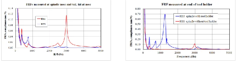
In this study, a commercial high speed spindle was employed for tests. Figure 1 illustrates the vibration testing configuration of the spindle with tool holder (BT30). The accelerometers were mounted on the spindle nose (point 1) and spindle tail (point 2), respectively to measure the vibration signals excited at the opposite side of spindle nose by the impact hammer. The frequency response functions were then assessed from the recorded FFT spectrum. The dynamic compliance associated with the dominant vibration modes were then extracted from measured frequency response functions for comparisons.
[image:2.595.132.462.313.389.2]
Figure 1. Configuration of vibration test of spindle.
Frequency response functions of Spindle Unit
The measured vibration responses of the spindle units are illustrated in Figure2, which are expressed in terms of the compliance varying with frequency. The frequency responses termed as H11 and H21 were measured at nose (point 1) and tail (point 2) of the spindle under excitation at the nose (point 1).As found, the spindle shows four fundamental modes at 360, 740, 2450 and 2970 Hz, in which the spindle shows a great deflection at spindle nose under excitation of the fourth mode of 2970 Hz. Besides, the frequency response(H33) was measured at the end of tool holder. It is found that the spindle with tool holder behaves four fundamental modes at about 347, 713, 1243 and 3140 Hz. The first two modes are similar to those of the spindle unit without tool holder, while the third mode shows great compliance, indicating the effect of the addition of tool holder.
Figure 2. Frequency response functions (H11, H21 and H33) of spindle tool module.
Modeling of the Spindle-Tool Holder System
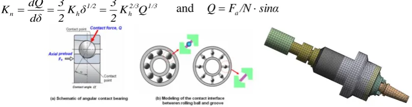
[image:2.595.103.493.569.670.2]Modeling of Angular Contact Bearing
As shown in Figure 3, the contact force between the rolling ball and the raceway can be related to the local deformation of contact point by the Hertzian expression as follows:
3/2 hδ
K
Q (1)
where Q denotes the contact force and is the elastic deformation at the contact point. Kh represents the Hertz constant, which is determined by the contact geometry of the ball groove or raceway and the material properties of the contacting components. The normal stiffness at a specific preload can then be obtained as
1/3 2/3 h 1/2
h
n K Q
2 3 δ K 2 3 dδ dQ
[image:3.595.72.477.224.329.2]K and QFa/Nsinα (2)
Figure 3. Modeling of the angular contact bearing and finite element model of spindle tool.
Finite Element Model of Spindle Unit
Figure 3 shows the finite element model of the spindle bearing system, which was meshed with hexahedron elements with 62,614 elements and 187,021 nodes. In this model, the ball bearing in spindle was simplified as the outer and inner raceways by neglecting the rolling balls. The surface contact elements were introduced at the rolling interface between the inner and outer raceways. The contact stiffness of front and rear bearing was respectively calculated as 426 and 455 N/m according to the Eq. 1 and 2. The contact interface between the tool holder and spindle nose was also modeled by using surface contact elements with the adequate contact stiffness. The stiffness was identified by comparing the frequency response functions obtained from FE prediction and experimental measurements. In finite element modeling, all components were assumed to have the material properties with elastic modulus E = 200 GPa, Poisson’s ratio = 0.3, and density = 7800Kg/m3. The modal analysis and harmonic analysis were conducted to assess the fundamental vibration modes and the dynamic behaviors, respectively. The results were used to validate the spindle model for further creation of the full milling machine model.
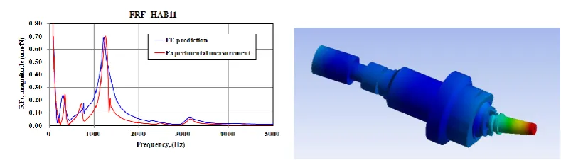
Validation of Spindle Model
Figure 4. Comparison of the predicted and measured frequency responses of the spindle with tool holder.
[image:4.595.197.400.369.494.2]Modeling of Spindle Tool System
Figure 5 illustrates the finite element model of spindle tool system, which is composed of vertical column, head stock, spindle tool module and feeding mechanism. Basically, all structural components of the system were meshed hexahedron elements with 115,375 elements and 324,961 nodes. The linear components in the feeding mechanism of the spindle head stock such as ball screw and the linear guide modulus were included in the finite element model. Similar to the case of ball bearing, the rolling interfaces between rolling balls and raceways were simulated by using surface to surface contact elements with adequate contact stiffness. The rigidity of the linear guides is 1.0kN/μm and 3.0kN/μm in horizontal and vertical directions, respectively. The overall contact stiffness at ball groove was estimated as 1.62 kN/μm according to the specifications of the ball screw.
Figure 5. Solid model and finite element model of the vertical spindle tool module of a milling machine.
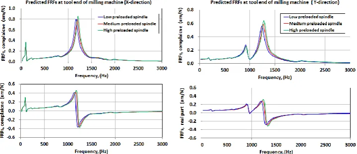
In this study the effect of bearing preload on the dynamic characteristics of a milling tool was concerned. For this, three different preload amounts were assumed in the spindle bearings, which were set at standard preload, lower preload and high preload, respectively. For lower preloaded spindle, the bearing preload was decreased by 20% of standard preload. For higher preloaded spindle, the bearing preload was increased by 20% of standard preload. According to study [10], damping ability at the rolling interface was affected by the amount of bearing preload, which shows a variation in damping by about 5% in negative way with the adjustment of bearing preload. In finite element harmonic analysis, a modal damping ratio of 2.5 % was assumed at dominant vibration mode of a spindle system with standard preload. Again, harmonic analysis was performed to measure the frequency response at the end of the tool holder under the forces in X and Y directions, respectively, which was the important parameters for evaluation of the machining stability [7].
Dynamic Characteristics of Milling Tool
0.645μm/N, respectively. It is found that compliance in X direction is higher than in Y direction, showing the unsymmetrical effect of the structure of the vertical spindle tool system. Besides, the compliance or dynamic stiffness was found to change with the changing of the spindle bearing preload. The spindle with high bearing preload shows a larger compliance, about a difference of 7-15%, as compared to the lower preloaded one. Actually, this can be ascribed to the fact that the dynamic compliance or stiffness of the milling tool is determined by the product of the damping ratio and stiffness of the spindle tool system. When the reduction rate of the modal damping with the increasing bearing preload is higher than the increase of the bending stiffness, it follows causing a decrease of the dynamic stiffness or increase of the compliance.
[image:5.595.118.478.333.489.2]On the other respect, the machining stability of the cutter is determined by the maximum value of the negative real part of the frequency response function. It is found from Figure 6 that the milling cutter installed in spindle with medium preload shows a higher critical cutting depth, about 7-14% as compared with the low or high preloaded spindles. Overall, current results imply that increasing the bearing preload is not favorable to increase the dynamic performance. To the contrary, this may lessen the material remover rate of the spindle tool system at high speed machining. Through the modeling approach proposed in this study, the improvement of the dynamic performance and machining stability of the spindle tool system can be achieved by appropriately adjusting the bearing preload of the spindle tool in assemblage.
Figure 6. Predicted vibration responses of the milling tool with different bearing preload.
Conclusions
The study investigated the variation of the dynamic characteristics of a milling system with the adjustment of the spindle bearing preload. Based on the results, the following conclusions are drawn:
1. The finite element model of the spindle module was experimentally validated and implemented
into a milling machine model to simulate the frequency response functions of the spindle tool. The prediction accuracy is determined by the modelling of the rolling interface of ball bearings in spindles and the interface characteristics between tool holder and spindle nose.
2. The dynamic compliance of the milling machine can be affected to vary with the changing of the
spindle bearing preload. However, a high preload may not be favourable to increase the limit cutting depth of the milling system in stable machining. To the contrary, the milling machine with low or medium preload spindle can be expected to have larger cutting depth.
3. The methodology presented in this paper can be applied to develop a whole milling system at design phase to achieve the desired dynamic characteristics and machining performance.
References
[2] M. A. Alfares, A. A. Elsharkawy. Effects of axial preloading of angular contact ball bearings on the dynamics of a grinding machine spindle system. J. Mater. Proc. Tech. 136 (3) (2003) 48–59.
[3] S. A. Spiewak, T. Nickel. Vibration based preload estimation in machine tool spindles, Int. J. Mach. Tool. Manu. 41(4) (2001) 567–588.
[4] A. Gunduz, J. T. Dreyer, R. Singh. Effect of bearing preloads on the modal characteristics of a shaft-bearing assembly: experiments on double row angular contact ball bearings. Mech Syst Signal Process. 31 (2012) 176–195.
[5] J. Tlusty, M. Polacek. The stability of machine tools Against self-excited vibrations in machining. ASME Int. Res. in Production.1 (1963) 465–474.
[6] E. Abele, Y. Altintas, C. Brecher. Machine tool spindle units. CIRP Ann. Manuf. Technol. 59 (4) (2010) 781–802.
[7] E. Ozturk, E., Kumar, U., Turner, S., Schmitz, T. Investigation of spindle bearing preload on dynamics and stability limit in milling. CIRP Ann. Manuf. Technol. 61(1)(2012) 343–346.
[8] C.W. Lin, J.F. Tu. Model-based design of motorized spindle systems to improve dynamic performance at high speeds. J. Manuf. Proc. 9(2)(2007) 94–108.
[9] S. Jiang, H. Mao. Investigation of variable optimum preload for a machine tool spindle. Int. J. Mach. Tool. Manu. 50(1)(2010)19–28.