2018 International Conference on Computer, Communications and Mechatronics Engineering (CCME 2018) ISBN: 978-1-60595-611-4
Method of Mobile Robot Navigation for Positioning on the Road in
Forest Area
Andrey Sergeevich Karpenkov
1,*and Oleg Vladimirovich Martynov
21
Furmanova str, 14, App. 88, Kovrov, Vladimirskaya obl., Russian Federation
2Degtyareva str, 4, App. 71, Kovrov, Vladimirskaya obl., Russian Federation
*Corresponding author
Keywords: Vision system, Navigation, Digital video signal processing, Unmanned transport systems.
Abstract. The article is devoted to the method of processing data from a laser scanner for solving a
navigation problem when a mobile robot moves along a road on rough and wooded terrain, as well as the task of avoiding obstacles. A comparative analysis of methods for solving these problems. It is shown that the proposed method allows not only to solve the problem of fast and efficient identification of the road boundaries when a mobile robot moves across rough and wooded areas, but also to identify the presence of an obstacle along the way and distance to it.
Introduction
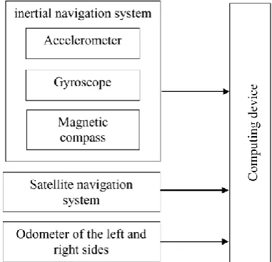
[image:1.595.200.391.456.640.2]Navigation has always been and is a non-trivial and complex mobile robot system. The technical and tactical characteristics of the mobile robot depend on the choice and implementation of the navigation system. As a rule, the majority of navigation systems for ground-based unmanned systems are based on the integration of odometer readings (mechanical or visual), gyroscope and satellite navigation system. An exemplary functional diagram of a typical mobile robot navigation system is shown in Figure 1.
Figure 1. Functional diagram of a typical mobile robot navigation system.
(RTK GPS) is used as the main navigation system of a mobile robot. It allows you to get an error in determining the location of no more than 10 cm. However, for its operation it is necessary to ensure a stable connection between the fixed base station and the robot itself, in order to transfer differential corrections from the base to the robot. As a rule, various VHF modems or GSM cellular network modems are used as a communication channel, whose range is also limited. In the case of an unstable signal reception from a satellite navigation system, the solution of the navigation problem rests on an integrated navigation system consisting of a mechanical odometer and a gyroscope. This leads to large errors (more than 10 km with a route of 100 km) positioning when moving over long distances. The accuracy of such a navigation system strongly depends on the type of gyroscope (micromechanical, fiber optic, laser) and on the state of the roadbed (the presence of wheel slip, different underlying surface of the left and right wheels).
The task of determining the location of a mobile robot is closely related to the task of the trajectory movement. As a rule, the robot is required to move along the existing road, bypassing the existing obstacles on the way.
For the recognition of obstacles to the movement of a mobile robot meets the vision system. Among the widely used vision systems used in robotics, the following can be singled out: ultrasound sonars, laser scanners, optical range video cameras with various kinds of backlights, radar sensors.
As a rule, the above problems are solved by separate systems independently of each other. At the same time, the existing road has a set of characteristic features, given which it is possible to improve the accuracy of localization of a mobile robot on the road. These signs include the boundaries of the road, recognizing the location of which relative to the current position of the mobile robot, you can calculate the necessary correction factor for calculating the course.
As a rule, data from the video camera is used to recognize the boundaries of the roadway and the presence of obstacles on it.
The general algorithm for the operation of such systems is as follows. First, perform the image calibration of the video camera in order to reduce image distortion. Then, the original RGB image is converted into HSV format—it is convenient to select specific color ranges in this color model. The next step is binarization (image conversion into a binary mask with colors of interest) and image vectorization by using a Canny border detector and Hought transformation. In order to improve the accuracy of recognizing the boundaries of the road, the upper part of the image (as a rule, above the horizon line) is not taken into account when carrying out further processing. Then, on the resulting image, there are separate lines belonging to the border of the road.
Such lines must satisfy a number of conditions:
the line cannot be horizontal and should have a moderate slope;
the difference between the slopes of the boundary line of the road and the candidate line cannot be too high;
the line should not be far from the borders of the road to which it belongs; the line should be below the horizon.
The lines selected at the previous step are subjected to additional filtering taking into account the data obtained in the previous frame and the already stable lines corresponding to the border of the roadway are obtained [2].
This method has several limitations. Firstly, it does not work well on a winding road, because in the method itself, it is the detector of the lines, not the curves. Secondly, this method does not work on sections of roads with frequent changes of direction and illumination, since the detector no longer has time to follow the lines due to the accumulation of errors in determining the boundaries of the roadway [3].
Methods
graph of the dependence of the distance on the angle according to the readings of the rangefinder is shown in Figure 2.
Figure 2. Graph of the dependence of the distance on the angle as indicated by the laser scanner.
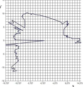
As can be seen from the figure, the graph has a smooth curve section; this section corresponds to the road surface. Let's display the graph in the Cartesian coordinate system y (x), where y corresponds to the axis directed along the center line of the scanner (with a zero angle), and axis x directed perpendicular to y along the road surface. The resulting graph is shown in Figure 3.
[image:3.595.165.434.476.756.2]With this transformation, the smooth region becomes close to a straight line. To automatically determine the boundaries of this area, we use the Ordinary Least Squares method (OLS) for the scan window - a section of a graph of a given width. The window width may vary depending on the task (look for or ignore obstacles on the road, etc.), but, as a rule, does not exceed the width of the road. Based on the window OLS, we obtain the standard deviation of the dependence y (x) from a straight line within the window (σi) depending on the scan angle corresponding to the beginning of the
window (αi) using equations (Eq. 1, Eq. 2):
𝜎𝑖 = √∑𝑁𝑗=1𝑘 (𝑦𝑖+𝑗− (𝑎𝑖∗ 𝑥𝑖+𝑗+ 𝑏𝑖))2. (1)
𝛼𝑖 = 𝛼0+ 𝑖 ∗ 𝑑𝛼. (2) In equations above (Eq. 1, Eq. 2) i is the value of the discrete number (scan step) at the beginning of the scan window, j is the value of the number of discretes within the scan window, yi + j, xi + j – y and x
coordinate of the scanning point i + j, respectively, ai, bi are the direct coefficients in within the OLS,
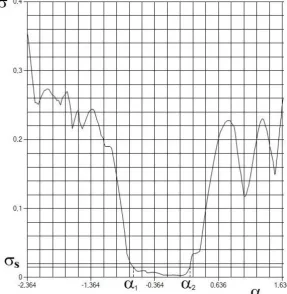
α0 is the initial scan angle, dα is the magnitude of the discrete values. The graph of such dependence is
[image:4.595.149.437.315.610.2]shown in Figure 4.
Figure 4. Graph of the standard deviation σ of the dependence y(x) from a straight line within the window from the scan angle α.
values. These changes can also be traced, which in turn will recognize the presence of an obstacle, its size and location.
Summary
Thus, the proposed method allows not only to solve the problem of quick and effective identification of the boundaries of the road when the mobile robot moves over rough and wooded areas, but also to identify the presence of obstacles along the way and distance to it. The advantages of the proposed method can also be attributed to its invariance to the shape of the boundaries of the roadway and its illumination.
Acknowledgement
This research was financially supported by the Ministry of High Education and Science of the Russian Federation as part of the state assignment number 8.12192.2018 / 11.12.
References
[1] Vlasov S.M., Boykov V.I., Bystrov S.V., Grigoriev V.V. Contactless means of local orientation of robots. - SPb: ITMO University, 2017.
[2] 2. M Kumar, Ammu & Simon, Philomina. (2015). Review of Lane Detection and Tracking Algorithms in Advanced Driver Assistance System. International Journal of Computer Science and Information Technology. 7. 65-78. 10.5121/ijcsit.2015.7406.