DYNAMIC SIMULATION OF SPIRAL BEVEL GEAR BASED
ON SOLIDWORKS AND ADAMS
1 JIHUI LIANG, 2LILI XIN
1 School of Automobile and Traffic, Shenyang LIGONG University, Shenyang 110159, Liaoning, China 2 College of Engineering, Shenyang Agricultural University, Shenyang 110866, Liaoning, China
ABSTRACT
Spiral bevel gears are one of basic mechanical units to transmit motion between concurrent axes. The transmission has quite a few merits, such as the big overlap ratio, the high loading capacity, the high transmitting efficiency, the stability and the small noises, and they are widely used in automotive vehicle, planes, machine tools and all kinds of machines. Mechanical properties of spiral bevel gear have significant influence on the whole mechanical structure and play an important role in the system optimization, strength check, fault diagnosis and fault prediction, and gear tooth meshing-dynamic load is an important issue in the gear research field. Three-dimensional models of spiral bevel gears are created by SOLIDWORKS and then converted to ADAMS by means of data exchange interface between SOLIDWORKS and ADAMS. By the contact algorithm theory of multi-body dynamics and ADAMS, the dynamic simulation of the spiral bevel gears mesh is specified. The curves of angular speed, torque and meshing force on the spiral bevel gears are obtained by simulation calculation, which provide references to research on dynamic characteristics of gear driving device.
Keywords: Spiral Bevel Gear, ADAMS, Gear Meshing, Dynamics Simulation
1. INTRODUCTION
Spiral bevel gear is the most important industrial mechanical part. Its main feature is that the axis of drive gear and that of driven gear would intersect vertically here. Due to the influence of overlapping of gear end-face, more than two pairs of gears mesh at the same time. Thus it could bear much loading. Moreover, its teeth do not mesh on the full length. Instead of that, one end of the teeth would steer towards the other end steadily, so the gear boasts the advantages of smooth works, little noise and vibration facilitating the fact that the gear could be used in cars, tractors, machine tools and other dynamic and motion-transmission devices. Its mechanical behavior and working performance play an important role in the whole machine.
It is essential for reliability design, checking calculation and fault diagnosis of gear system to know how to have a good grasp of mechanical properties and movement characteristics of gear transmission, [1, 2, 3] introduce the detection of meshing force in gear meshing process. It is very difficult to detect the interference condition of gear profile, the force of gear surface and gear impact force. [4, 5, 6] discuss the influence of vibration, noise, dynamical load, big stress and distortion caused by high-speed and heavy-duty on the safety and stability of the machine. It is instant to carry on
the study on the gear transmission system with high property.
2. MODELING OF SPIRAL BEVEL GEAR
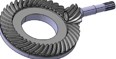
[image:2.612.99.296.307.408.2]Plug-in GearTrax of SOLIDWORKS software could help to finish precise modeling of spiral bevel gear [9, 10]. After-assembling gear is just as that in Figure1. The pair of bevel gear belongs to drive axle and the small bevel gear is drive gear with two-way operation and loading in smooth. The maximum power of transmission of the gear system is 140KW. The transmission ratio is 6.143. The life expectancy is 10 years. Pinion is made of 20CrMnTi with carburization and quenching treatment. Its surface hardness is 54~62 HRC. Large gear is made of 20CrMnTi with carburization and quenching treatment. Its tooth face hardness is 52~58 HRC . Parameters of spiral bevel gear are in Table 1.
[image:2.612.91.297.471.627.2]Figure 1: Three-Dimensional Models Of Spiral Bevel Gears
Table 1: The Proper Geometric Parameters Of Spiral Bevel Gears
Parameters Driving gear Driven gear
Tooth number 9 40
End module /mm 9 9
Pressure angle /(°) 20 20
Face angle/(°) 15.97 79.97
Root angle /(°) 10.03 74.03
Breadth of tooth /mm 60 54
Tooth addendum /mm 7.65 7.65
Tooth dedendum /mm 9.342 9.342
Nodal bevel angle /(°) 13 77
Nodal bevel distance /mm
180 180
Helix angle /(°) 35 35
Shaft angle /(°) 90 90
Change the after-assembling bevel gear module into file format parasolid in SOLIDWORKS and introduce CAD geometric module by exchange module in ADAMS.
3. BUILDING DYNAMIC MODULE
3.1The Choices of Contacting Forces
In ADAMS, there are two types of contacting forces. One is contacting force based on Impact function and the other is based on Restitution function. Impact uses stiffness coefficient and damping coefficient to calculate contacting force but Restitution uses coefficient of restitution. In the article, Impact function is employed. And the basic form is Impact(s,n,s0,K0,j,C0,d) : s is actual
distance between objectives in the contacting process; n is the relative rotation speed of objectives when the two contact; s0 is initial displacement value of contacting force excitation;
0
K is stiffness coefficient; j is contacting force index;C0 is damping coefficient ;d is inertia center distance of two contacting objectives. The function takes comprehensive consideration of many factors in gear incentive, so it is a pretty precise method of stimulation. Mathematical calculation method of impact function is:
)) 0 1 (
) ( 0 (
0 0 0
0 0
, ,s d, s,s STEP n C
s s ,K
max j
− •
•
− − •
(1)
STEP is a haversine step function.
Whens0−s≤0, impact function value is zero
and two gears do not contact.
Whens0−s>0, two gears contact.
The value of contacting force is relevant to stiffness coefficient K0 , deformation s0−s ,
contacting force index j and damping coefficient
0
C . Figure 2 is impact force model of ADAMS, when the distance between I and J decreases to initial displacement value ( s0 ), body I and J
begin to collide. Collision force is made of elastic force (rigid force) and damping force (viscous force), and rigid force is proportional to K0 and inversely proportional to penetration, which is the penetration function about free length range of I
andJ. Damping force is the function of penetration velocity, and its direction is to the opposite movement direction. Impact force is related to stiffness coefficient (K0), contacting force index (j), damping coefficient ( C0 ) and inertia center distance of two contacting objectives ( d ). K0
Figure 2: Impact Force Model Of ADAMS
3.2 The Choices of Tooth Contacting Theory and Contacting Parameters
Impact force of teeth contact can be the same to collision of two variable camber radius cylinders. The problem can be solved in Hertz static elastic contacting theory [11].
According to Hertz contacting theory in which contacting area is round:
3 1
2 2 2
) 16
9 (
RE P
R a
= =
δ (2)
So the relation between contacting normal force
P and deformation δ is 2 3
0δ
K
P= . Stiffness coefficient K0 depends on the materials and structural shapes of contacting objectives.
E
R
K
21
0
3
4
=
(3)Among which:
2 1
1 1 1
R R
R = + (4)
1
R and R2 are contacting radius of contacting objects in the contacting point.
2 2 2 1
2
1) (1 )
1 ( 1
E E
E
µ
µ −
+ −
= (5)
1
µ and
2
µ are Poisson ratios of contacting objectives. E1 and E2 are elastic modulus.
Since materials are both 20CrMnTi, its Poisson ratio µ1=µ2=0.25 ,
5 2
1=E =2.07×10
E
N/mm2. Insert the figures into formula 5 and
5
10 1 . 1 ×
=
E N/mm2 . As to formula 4,
061 . 33
=
R N/mm2. Insert E and Rinto formula 3, stiffness coefficient K0 =8.433×10⁵ N/mm2.
Referring to empirical value, contacting index jis 2.2; damping coefficient c is 100Ns-1; deep friction and lubrication d is 0.1 mm. To get a real situation of bevel gear meshing, gear adopts friction and lubrication, while static friction coefficient is 0.5 and dynamic friction coefficient is 0.3.
3.3 Restriction Imposition of Virtual Prototype Module
Based on virtual prototype module in the article, add two rotating pairs and a contacting pair to bevel gear. Pinion is set to be driven gear as in Figure 3. Constant speed drive of driving wheel is 900°/s (150r/min). Constant loading torque of motor wheel is 15713000Nmm. To prevent loading from drastic changes, use STEP function to enable the gentle loading imposition in 0.1 second; That is
) 15713000 ,
1 . 0 , 0 , 0 , (time
STEP ( time is
independent variable). Loading torque imposed by
[image:3.612.319.516.364.493.2]STEP function is in Figure 4. Dynamic simulation is with simulation time of 0.4 second and step size of 100[12].
Figure 3: Model Of Spiral Bevel Gears In ADAMS
Figure 4: Loading Torque On Driving Gear
4. RESULT AND ANALYSIS OF
SIMULATION
[image:3.612.91.299.427.628.2] [image:3.612.315.519.511.642.2]Figure 5: Angular Speed Of Driving Gear
[image:4.612.95.297.71.219.2]Figure 6 is rotation speed of driven bevel gear. The curve changes as time (t) changes. It shows that from the initial stage of movement of driven bevel gear, under the co-influence of collision between gears and gradually increasing torque on driven bevel gear, rotation speed vary a lot. 0.05 seconds later, the gear movement goes smoothly when rotation speed is about 200 °/s in accordance with theoretical rotation speed.
Figure 6: Angular Speed Of Driven Gear
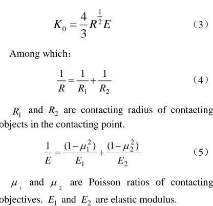
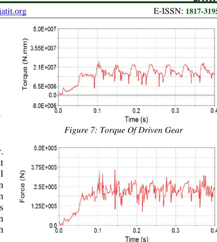
Torque curve of driven gear and teeth meshing force curve are seen in Figure 7 and Figure 8. Referring to analysis of simulation, in 0~0.1 second, since driven gear loading torque increases, the fluctuation range of driven gear torque is greater and so does the range of meshing force. After 0.1 second, the loading torque stays table and so does torque which is about the same as loading torque (15713000Nmm). All meshing forces go up and down around a mean value(transmission load) in certain amplitude and their cycles and amplitudes are stable. That is periodic tooth mesh in and out. After 0.1 second, compare mean value of meshing force with the theoretical calculation value and they are almost the same which verifies the correctness of simulation.
Figure 7: Torque Of Driven Gear
Figure 8: The Curve Of Meshing Force
5. CONCLUSIONS
The precise modeling of spiral bevel gear is based on SOLIDWORKS software. Through seamless interface program of SOLIDWORKS and ADAMS, virtual prototype of gear meshing parameterization under ADAMS is realized; introduce Hertz contacting theory into simulation module and impose contacting force actively between main reducer and driven gear. The result is in accordance with theoretical calculating results, which verifies the feasibility of modeling design of combination of SOLIDWORKS and ADAMS software and dynamics simulation. The result of simulation further verifies that stiffness excitation and meshing impulse excitation could produce cyclical fluctuation. The method makes up for the deficiency of modeling of mechanical parts with complicated and accurate positioning; at the same time, it could serve as reliable basis for strength check, optimization, vibration and noise analysis of spiral bevel gear transmission system and other gear transmission system, of important engineering application value.
ACKNOWLEDGEMENTS
[image:4.612.92.298.331.443.2]REFERENCES:
[1] Yongjun Wu, Jianjun Wang, Qinkai Han, “Contact finite element method for dynamic meshing characteristics analysis of continuous engaged gear drives”, Journal of Mechanical Science and Technology, Vol. 26, No. 6, 2012, pp. 1671-1685.
[2] A. Palermo, D. Mundo, R. Hadjit, W. Desmet, “Multibody element for spur and helical gear meshing based on detailed three-dimensional contact calculations”, Mechanism and Machine Theory, Vol. 62, 2013, pp. 13-30.
[3] A. Fernandez del Rincon, F. Viadero, M. Iglesias, P. García, A. de-Juan, R. Sancibrian, “A model for the study of meshing stiffness in spur gear transmissions”, Mechanism and Machine Theory, Vol. 61, 2013, pp. 30-58. [4] Faydor L. Litvin, Qiming Lian, Alexander L.
Kapelevich, “ Asymmetric modified spur gear drives: reduction of noise, localization of contact, simulation of meshing and stress analysis”, Computer Methods in Applied Mechanics and Engineering, Vol. 188, No. 1-3, 2000, pp. 363-390.
[5] Faydor L. Litvin, Daniele Vecchiato, Eugene Gurovich, Alfonso Fuentes, Ignacio Gonzalez-Perez, Kenichi Hayasaka, Kenji Yukishima, “Computerized Developments in Design, Generation, Simulation of Meshing, and Stress Analysis of Gear Drives”, Meccanica, Vol. 40, No. 3, 2005, pp. 291-323.
[6] Jiandong Sun, Wenyu Fu, Hong Lei, E. Tian, Ziping Liu, “Rotational swashplate pulse continuously variable transmission based on helical gear axial meshing transmission”,
Chinese Journal of Mechanical Engineering, Vol. 25, No. 6, 2012, pp. 1138-1143.
[7] X. Hua, T. C. Lim, T. Peng, W. E. Wali, “ Dynamic analysis of spiral bevel geared rotor systems applying finite elements and enhanced lumped parameters”, International Journal of Automotive Technology, Vol. 13, No. 1, 2012, pp. 97-107.
[8] S. H. Suh, D. H. Jung, S. W. Lee, E. S. Lee, “Modelling, Implementation, and Manufacturing of Spiral Bevel Gears with Crown”, The International Journal of Advanced Manufacturing Technology, Vol. 21, No. 10-11, 2003, pp. 775-786.
[9] Zhenyun Duan, Houjun Chen, Zhilan Ju, Jian Liu, “Mathematical model and manufacture programming of loxodromic-type normal circular-arc spiral bevel gear”, Frontiers of Mechanical Engineering, Vol. 7, No. 3, 2012, pp. 312-321.
[10] Faydor L. Litvin, Alfonso Fuentes, Ignacio Gonzalez-Perez, Luca Carvenali, Kazumasa Kawasaki, Robert F. Handschuh, “Modified involute helical gears: computerized design, simulation of meshing and stress analysis”,
Computer Methods in Applied Mechanics and Engineering, Vol. 192, No. 33–34, 2003, pp. 3619-3655.
[11] F.L. Litvin, I. Gonzalez-Perez, A. Fuentes, K. Hayasaka, K. Yukishima, “Topology of modified surfaces of involute helical gears with line contact developed for improvement of bearing contact, reduction of transmission errors, and stress analysis”, Mathematical and Computer Modelling, Vol. 42, No. 9-10, 2005, pp. 1063-1078.
[12] He Zhang, Lin Hua, Xinghui Han, “Computerized design and simulation of meshing of modified double circular-arc helical gears by tooth end relief with helix”,