THE RESEARCH ON NONLINEAR CHARACTERISTIC OF
FIXED DISPLACEMENT PUMP–VARIABLE MOTOR
SYSTEM
1AI CHAO, 2KONG XIANGDONG, 3WANG JING
1Hebei Provincial Key Laboratory of Heavy Machinery Fluid Power Transmission and Control, Yanshan
University, Qinhuangdao 066004, China
2Key Laboratory of Advanced Forging & Stamping Technology and Science ( Yanshan University),
Ministry of Education of China, Qinhuangdao 066004, China
E-mail: [email protected], [email protected], [email protected]
ABSTRACT
In different system working points, response characteristics of the fixed displacement pump – variable motor volume speed control system are different. For example, after the input speed of the fixed displacement pump and the pivot angle of the variable motor are changed, the same variation in pivot angle of the motor causes different variation in speed of the motor. Therefore, multiplication nonlinear law works here. As for this problem, small signal linearization method is adopted to analyze a fixed displacement-variable motor system transfer function and obtain the relationship among natural frequency, damping ratio and the pivot angle of the motor. Further identify the experimental data, experimental value for natural frequency and damping ratio of the system is obtained. Also, fitting method is adopted to obtain the relationship among natural frequency, damping ratio and pivot angle of the motor, which lays the foundation for the application of fixed displacement pump-variable motor speed control system.
Keywords: Fixed Displacement Pump – Variable Motor Volume Speed Control System, Multiplication Nonlinear Law, Small Signal Linearization Method, System Identification
1. INTRODUCTION
As for the fixed displacement pump-variable motor positive displacement speed control loop, the main feature is constant-power speed regulation. But when it runs at high speed and the displacement of motor is small, the speed rigidity of the loop is very low[1].
Specific to the characteristics of the fixed pump-variable motor loop, Liu Keming in Guangxi University did the static analysis and speed characteristics deduction. The research found out that regulation range for the actual maximum speed of the limit hydraulic motor due to the existence of “dead zone”[2].On the basis for analyzing the relationship between the speed and displacement, Michael in Purdue University designed and verified the fixed displacement pump-variable motor system for solving the impulse problem in the driver cycle so that the system efficiency is successfully improved under the conditions of low pump displacement of the traditional hydraulic system and low actuating speed[3]. Aachen University did theoretical and experimental studies of the fixed displacement pump-variable motor closed system,
and the experimental data show that the efficiency up to 85%[4]..
Professor Kong Xiangdong in Yanshan University did the simulation research for the characteristics of constant speed output control in fixed constant pump-variable motor closed system. And also, he analyzed the influence of factors such as load torque fluctuation, speed input fluctuation and variation of inertia moment at load end on constant speed output control[5]. As for the fixed displacement pump-variable motor system, Hu Na in Yanshan University established the transfer function and analysised characteristics influencing factorso of the system[6]. Zhang Gang in Yanshan University analysed the impact of different factors on the fixed displacement pump-variable motor system power control using the mechanism modeling techniques[7].
research only established system model and did preliminary analysis, there is no in-depth study .
On the basis of the above analysis, this paper analysed nonlinear characteristics and speed response characteristics of the the fixed displacement pump-variable motor system. It also established the mechanical model and got the transfer function. Theory and experiment in this thesis are both analyzed.
2. FIXED DISPLACEMENT PUMP–
VARIABLE MOTOR SYSTEM
CHARACTERISTIC ANALYSIS AND MATHEMATICAL MODEL
2.1. Multiplication Nonlinear Characteristic Of the Fixed Displacement Pump-Variable Motor System
Fixed displacement pump-variable motor volume speed regulation system adjusts the speed nonlinearly. The motor flow is as follows:
Q=Km⋅ γ ⋅ωm m (1)
As the pivot angle of variable displacement mechanism γm and the speed of variable motor ωm are both variables, the cross product is nonlinear. As shown in Figure1, displacement Vm is in inverse proportion to speed ωm when the input flow of the displacement pump isQ1. When the motor works at different speeds, the speed ωm and pivot angle γm of the variable mechanism is of nonlinear relationship; when the output discharges of the fixed displacement pump varies asQ1, Q2 andQ3, the same motor speed has different pivot angles of variable mechanism. Besides, the rates of change between speed and tilting tray angleK1, K2and K3
are different.
0 V1 V2 V3 Vm
1
K K2 K3
m
ω
1
Q
2
Q
3
Q
Figure1 Curve Of Relationship Between Speed And Displacement Of Motor Under Different Input Flows
2.2. Mathematical Model For Fixed Displacement Pump-Variable Motor System
(1) Quantitative pump drive torque balance equation:
(
)
22d
d
p p
p p h l p p p p
d
T D p p J B G
dt t
− − = θ + θ + θ (2)
Where Tp is driving torque on the pump, Dp is
the pump displacement, ph is high pressure, pl is the low pressure, Jp is total inertia, θp is pump
swing angle, Bp is viscous damping coefficient,
p
G is the spring stiffness of load;
Laplace transforms of the increment equation is as follows:
2
p p h p p p p p p
T −D p =J s
θ
+B sθ
+Gθ
(3)(2) Quantitative pump flow equation:
(
)
p p p ip h l ep h
q =D
ω
−C p −p −C p (4)Where qp is the pump flow, ωp is the pump
speed, Cip is the inner leakage coefficient, Cep is the outer leakage coefficient.
Laplace transforms of the increment equation is as follows:
Qp =D sp θp−C ptp h (5)
(3) Flow continuity equation in the high pressure chamber of the fixed displacement pump -variable motor is as follows:
0 h
p m
e
V dp
q q
dt β
= + (6)
Where V0 is the total volume, βeis the integrated fluid bulk modulus.
The cross product of variables γ and d m
dt θ
forms a nonlinear equation. Small signal liberalization method, the method for taylor series expansion, is adopted to deal with linearization.
( )
m( )
[( )
0 ( )][ m( )
0 m( )]d t
t t t
dt θ
γ = γ + ∆γ θ• + ∆θ• (7)
( )
m( )
0 m0 ( ) m0 0 m0( )
d t
t t t
dt θ
γ =γ θ• + ∆γ θ• + ∆γ θ• (8)
(4) Load torque balance equation of the variable motor is as follows:
(
)
2 2d d
m m
m h l m m m m m
d
D p p J B G T
dt t
θ θ θ
− = + + + (9)
Where Dm is the motor displacement, Jm is inertia of the motor and load, θm is motor swing angle, Bm is viscous damping coefficient, Gm is the spring stiffness of load, Tm is driving torque on the motor.
The cross product of variables γ and
p
hforms a nonlinear equation. Small signal liberalization method, the method for taylor series expansion, is adopted to deal with linearization.( )
( )
[ 0 ( )][ 0 ( )]
h h h
p t p p t
γ
=γ
+ ∆γ
+ ∆ (10)Ignoring the second order infinitesimal, the following can be obtained:
( )
0 0 ( ) 0 0
h h h h
p p t p p t
γ
=γ
+ ∆γ
+ ∆γ
(11)Pivot angle of variable motor can be deduced from formula (3), (5), (8) and (11); it can be expressed as (12):
0 0
0 0
2 2 2
0 0 0 0
2
0 0
2 2 2 2 2 2
0 0 0
( )
( ) (1 )
[ s ( ) 1]
h t
p
m e t
m
m e t
m m
m
m m t m
e m m e m
V
P C s
Q C V
s T
K C
K K
J V J C B V
s s
K K K
θ β γ
γ γ γ γ β
θ
β γ γ β γ
+ − + + − + = + + + (12)
The block diagram for fixed displacement-variable motor system transfer function is shown in the Fig2. When the rigidities of the output ends of the motor and the fixed displacement pump are large,Gm =Gp =0.
K
mθ
m01
V
0β
es
C
t+
K
mγ
01 s
K
mγ
0K
mP
h01
J
ps+B
p1 s
γ
T
mω
mθ
mθ
pω
pT
pQ
pQ
m0P
h 1J
ms+B
mD
pD
pFigure2 The Block Diagram For Fixed Displacement - Variable Motor System Transfer Function
2.3 Variable Motor Speed Mathematical Model Simplification And Analysis
Transfer the formula (12) into the standard form as formula (13).
0 0
0 0
2 2 2
0 0 0 0
2
2
( )
( ) (1 )
2 s
( 1)
h t
m e p t
m
m e t
m m m hm hm hm V
p C s
Q C V
s T K C K K s s β θ γ
γ γ γ γ β
θ ξ ω ω • + − + + − + = + + (13)
Where,
ω
hm is the hydraulic natural frequency of the motor speed controlled channel,2 2 0 0 e m hm m K J V
= β γ
ω
Where, ξhp is the hydraulic damping ratio of the motor speed controlled channel
0
0 0 0
2
2
t e m m
hm
m m e m
C
J
B
V
K
V
K
J
=
β
+
ξ
γ
γ
β
The transfers function between variable motor speed and pivot angle of the variable motor can be expressed as (14):
0 0 0 2 0 0 2 2 ( ) 2 s 1 h t m e m m hm hm hm V
p C s
K s β γ ω γ ξ γ ω ω
θ• +
− +
=
+ +
(14)
system has different inherent characteristics when the pivot angles of the motor are different. Frequency is in proportion to the pivot angle of the motor; damping is in inverse proportion to the pivot angle of the motor.
3. FIXED DISPLACEMENT
PUMP-VARIABLE MOTOR SYSTEM
EXPERIMENTAL STUDY AND OPEN LOOP IDENTIFICATION
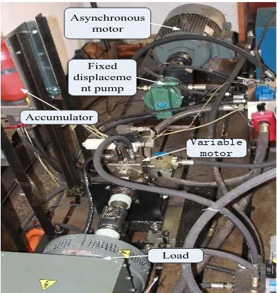
Open loop identification shall be done to the fixed-displacement pump-variable motor system to obtain the transfer function between speed and pivot angle of the motor under different positions of pivot angles for further soft parameter analysis. The structure of experimental table is shown in Figure3.
The working range of the variable motor adjustment displacement servo cylinder adopted in the experiment is±4mm. And the corresponding pivot angle of the variable motor is ±15°and the working range of the variable motor is ±40ml. It is believed that any two of the three factors, displacement, pivot angle and position of the servo cylinder are of linear relationships. What’s more, the three variables in this thesis are defined as dimensionless values in the interval [0, 1].
Open loop identification shall be done to the fixed displacement-variable motor system It can be seen from Figure4 that the natural frequency of the speed open loop is 3.68rad/s and the damping ratio is 0.349. It can also be known from Figure5 that the identification accuracy is 98.02%.
Asynchronous motor
Fixed displaceme
nt pump
Variable motor
Load Accumulator
Figure3 The Structure Of Experimental Table
The varying pattern for the natural frequency and damping ratio of system is shown in Table 1.
Figure4 Zero-Pole Curve
[image:4.612.98.298.485.697.2]Figure5 System Identification Precision Curve
Table 1 The Experimental Value Of The System Natural Frequency And Damping Ratio
0
γ
ω
h/(rad/s)ξ
0.6509 3.81427 0.3322 0.7548 4.4431 0.2787 0.8532 4.9997 0.2579 0.9258 5.4252 0.2356 Drawn the curve using the data in the table 1, which showing as figure 6 and figure 7.
0.6 0.7 0.8 0.9 1.0
3.0 3.5 4.0 4.5 5.0 5.5 6.0
motor pivot angle γ0/100%
na
tur
al
f
re
que
nc
y
ω
h/
(
ra
d
·
s-1
)
h
0
γ
=5.86
ω
h=5.86 0
ω γ
Figure6 The Relationship Between Motor Pivot Angle And Natural Frequency
M; measured Zr; fit: 98.02%
Time t/s
1 2 3 4 5 6 7 50
100 150 200 250
S
p
ee
d
Δ
n
/(r/
m
in
)
0 0
Real Axis 500
-1000 50
100 System: sys
Pole: -4.07 + 97.4i Damping: 0.0417 Overshoot (%): 87.7 Frequency (rad/sec): 97.5 System: sys
Pole: -12.8 + 3.45i Damping: 0.332 Overshoot (%): 32.1 Frequency (rad/sec): 3.38
Im
ag
in
ar
y
A
x
is
System: sys Pole: 15.4-40.7i Damping: -0.354 Overshoot (%): 329 Frequency (rad/sec): 43.5
0
-50 50
-500 0 1000
0.6
0.7
0.8
0.9
1.0
0.2
0.3
0.4
da
m
pi
ng
ra
ti
o
ξ
motor pivot angle
γ
0/
100%
-1
=0.22
0
ξγ
-1
=0.22 0
ξ
γ
Figure7 The Relationship Between Motor Pivot Angle And Damping Ratio
Linear relationship between the natural frequency and pivot angle can be obtained by linear fitting the experimental data:
ω =
h5 86
.
γ
0 (15)As shown in Figure8, fit the curve between damping ratio and pivot angle in accordance with the experimental data.
ξ =
0 22
.
γ
0−1 (16) (16)4. CONCLUSIONS
Speed response characteristics of the fixed-displacement pump and variable motor speed control system are analyzed theoretically and experimentally in this thesis so that theoretical analysis and experimental study are done to solve the multiplication nonlinear problem. The experimental study discovers that the system can operate stably when the range for pivot angles of variable motor is within the interval (0.6, 1.0) although the natural frequency of the system is in proportion to the pivot angle of the motor and the damping ratio is in inverse proportion to the pivot angle of the motor.
REFERENCES
[1] Li Shuai. The speed control system Characteristic of the pump control motor closed loop. Hangzhou, Zhejiang University, 2010: 1-3.
[2] Liu Keming. The static characteristics analysis of fixed displacement pump – variable motor volume speed control loop. Construction Machinery. 1989(12): 29-31.
[3] Holland, M., Harmeyer, K., and Lumkes, J. Electrically Controlled Fixed-Displacement Pump, Variable-Displacement Motor Hydrostatic Transmission. SAE Technical Paper 2006-01-3469. 2006, doi: 10.4271/2006-01-3469.
[4] Johannes Schmitz, Nils Vatheuer, Hubertus Murrenhoff. Hydrostatic drive train in Wind Energy Plants[C]//EWEA 2011 Brussels Europe´s Premier Wind Energy Event Scientific Proceedings European Wind Energy Conference & Exhibition. Brussels:EWEA, 2011:20-23.
[5] ChaoAi, Xiangdong Kong, Hao Li. Simulation Study on Constant Speed Output Control of Fixed Displacement Pump-Variable Displacement Motor Hydraulic System. Proceedings of 2011 International Conference on Fluid Power and Mechatronics. FPM 2011. Beijing, 2011: 276-281.
[6] Hu Na. Speed control characteristic research on the main transmission system of hydraulic
model wind generators. Qinghuangdao,Yanshan University, 2012:21-29.
[7] Zhang Gang. research on the power control in the main transmission system of the turbine
with hydraulic transmission. Qinghuangdao,Yanshan University, 2012:33-36.