DOS ASSEMBLER 5
DOSASM5
User's Guide
Version 3
January,
1976
Model Code No. 50019
~TAPOINT
-The Leader In
DI.per.ed Data· Proc ••• ing
PREFACE
This manual explains the operating instructions for the
ASSEMBLER 5 and defines the directives and macros which are
available to the, user. The programmer will find the Datapoint DOS
User's Guide helpful if more detailed systems information is
required, and the Datapoint 2200 Reference Manual should be
consulted for fUrther instruction definition.
TABLE OF CONTENTS
pa:ge
1. INTRODUCTION 1-1
2. STATEMENTS 2-1
2.1 LABEL FIELD 2-1
2.2 INSTRUCTION FIELD 2-2
2.3 EXPRESSION FIELD 2-3
2.4 EXAf<1PLES OF EXPRESSIONS 2-6
2.5 COMMENT FIELD 2-7
3. ASSEMBLER DIRECTIVES 3-1
3.1 INCLUDE 3-1
3.2 EQUIVALENCE 3-1
3.3 SET 3-1
3.4 SKIP 3-2
3.5 TABULATE PAGE 3-2
3.6 TABULATE MAYBE 3-2
3.7 DEFINE CONSTANT 3-2
3.8 DEFINE ADDRESS 3-3
3.9 LOCATION 3-3
3.10 ORIGINATE 3-4
3.11 USAGE 3-4
3.12 REPEAT 3-4
3.13 END 3-5
3.14 PERIOD 3-5
3.15 PLUS SIGN 3-5
3.16 ASTERISK 3-5
3.17 LIST 3-6
3.18 ERROR 3-6
3.19 IF 3-7
3.20 XIF 3-7
4. .A.SSEMBJ..JER MACROS 4-1
4.1 HL 4-1
4.2 DE 4-1
4.3 BC 4-1
4.4 MEMORY STORE 4-2
4.5 MEMORY LOAD 4-2
4.6 SHIFT RIGHT NUMBERIC 4-2
4.7 SHIFT LEFT NUMERIC 4-3
5. OPERATING PROCEDURES 5-1
5.1PARAMETERIZATION 5-1
5.2 EXECUTION-TIME COMMANDS 5-2
5.3 ASSEMBLER PASS ONE 5.4 ASSEMBLER PASS.TWO
5.5 CROSS-REFERENCE GENERATION 5.6 ASSEMBLY ERRORS
Appendix A. INSTRUCTION REPERTOIRE
Appendix B. MNEMONIC OPCODE REPERTOIRE
Appendix C. EXTERNAL COMMAND REPERTOIRE
Appendix D. OBJECT FILE FORMAT
Appendix E. SAMPLE PROGRAM
iii
CHAPTER 1. INTRODUCTION
Generating machine language programs for the Datapoint 2200 with ASSEMBLER 5 consists of using the DOS EDITOR to create one or more symbolic source file(s) comprised of mnemonic instructions, symbolic variables, and symbolic routine names which can then be processed' by the ASSEMBLER to create an absolute, executable object file which can be loaded and executed by the OPERATING SYSTEM.
,
Since ASSEMBLER 5 and this manual assume many details which are inherent to the DOS and 2200, a working knowledge of both the DOS and the 2200 VI and VII processors is recommended before
proceeding.
Basically, the ASSEMBLER is a program that assigns nUmerical values to symbols and puts out these values upon input of the associated symbols. Symbols in certain fields have preassigned values (such as instruction mnemonics) while other symbols are defined by the user (such as labels).
The value assigned to an instruction mnemonic is the binary bit configuration recognized by the 2200 processor for that
instruction. For example, the following instruction mnemonics have the following octal values:
ADB RET SU
0201 0007 0024
Symbols in fields other than the instruction field (except for the expression field in EXternal commands) may be defined by the user. Pre-defined symbols are kept separately by the
ASSEMBLER so that the user may define symbols that are the same as the pre-defined symbols without encountering any difficulties. For example:
LABEL INSTRUCTION EXPRESSl.QN
L1 AD 1
JMP CALL
L2 AD 2
CALL CALL SUBRl
INPUT INPUT
will not present a problem in differentiating the two CALL and INPUT symbols since the ones in the instruction field are
pre-defined and the ones in the label and expressio~ fields are user-defined.
Along with relating symbols to numbers, another major
function of the ASSEMBLER is to enable the programmer to reference a symbol that is defined later in the program. This is called FORWARD REFERENCING, and may be handled in a variety of ways. One of the simplest is to look at the source code twice. The first
look determines the definitions of all the symbols and the second look uses the symbols to produce the object code. Each "look" at the source code is ca lIed a "PASS". Therefore, we end up wi th a two pass assembly process.
An optional function of the ASSEMBLER is that of producing a tabularized listing of all user-defined symbols, their octal
value, and all references to them. This cross:"'reference table generation consists of recording all references to user-defined symbols during pass two, sorting the references, and merging them with their values.
The ASSEMBLER maintains two internal counters called the ADDRESS COUNTER and the LOCATION COUNTER. The ADDRESS COUNTER
indicates the memory address of the object code currently being generated and the LOCATION COUNTER indicates the memory address at which the object code currently being generated will be executed. These counters are usually the same except in the case of Located Code (see Section 3.9). Each time a byte of code is generated, both counters are incremented. The values of these counters are initially set to 010000 but directives are available for changing their values either initially or dynamically (see Sections 3 and 5). The cont~nt of the ADDRESS COUNTER when processing of the current line is initiated is usually displayed at the left side of the listing. When the Location flag is set by a LOC directive, the LOCATION COUNTER (identified by a trailing L) is displayed instead of the ADDRESS COUNTER. The symbol $ has special meaning in that it has the value of the'LOCATION COUNTER when processing of the current line began. For example:
ADRCTR OBJECT CODE SOURCE CODE
01000 SET 01000
01000 104 000 002 XXX JMP XXX
01003 104 003 002 DOG JMP $
01006 A EQU $
00001 B EQU 1
01006 123 123 DC 0123,83
05400L LOC 05400
05400L 104 000 013 C JMP $
05403 D EQU $
01013 LOC *
The ASSEMBLER maintains a stack of 16 dynamic Program Address Blocks (PAB'S) which may be used to locate data and code at
Assembly time. A PAB is actually an ADDRESS COUNTER which has been given a symbolic name. This name is not used as a dictionary entry but is used solely for the purpose of requesting an ADDRESS COUNTER swap with the current PAB (see Sections 3.10 and 3.11).
An ABSOLUTE PAB is defined by the ASSEMBLER and is implicitly used anytime the programmer neglects to Originate (ORG) and Use
(USE) additional PAB's (see Section 3.10 and 3.11). When a new PAB is requested, the current PAB's ADDRESS COUNTER is stored and the next available address associated with the requested PAB is placed in the ADDRESS and LOCATION COUNTERS.
The first word address and the length of each PAB is printed at the end of pass 1.
Example of PAB usage:
ADRCTR OBJECT ~ODE SOURCE CODE
01000 BUFFER ORG 01000
07000 CODE ORG 07000
00120 LTH EQU 80
07000 USE CODE
07000 002 000 120 DC *BUF1,LTH
07003 002 120 120 DC *BUF2,LTH
01000 USE BUFFER
01000 BUFI SK LTH
01120 BUF2 SK LTH
07006 USE *
07006 377 HALT
CHAPTER 2. STATEMENTS
A 2200 assembly code statement consists of a label field, an
instruction field, an expression field and a comment field. For
example:
1 4
LABEL
_2_
JTC
__3_
START THIS IS A COMMENT FIELD
Field 1 is the LABEL FIELD
Field 2 is the INSTRUCTION FIELD Field 3 is the EXPRESSION FIELD Field 4 is the COMMENT FIELD
The 2200 editor provides tabulation so that the fields may be
justified to begin in a certain column for ease of reading. Tab
stops at columns 9, 15 and 30 create a good appearance. However,
the ASSEMBLER only requires the following:
A non-space in the first column means that the first field is a label except for a leading period, plus, or asterisk, which deSignates the entire line as a comment line.
A space in the first column means no label and the first symbol on the l.ine is an in struction.
Scanning proceeds from left to right. One or more spaces
serve as delimiters for the LABEL and INSTRUCTION fields. Spaces may appear in the expression field without terminating the expression (see, however. Section 2.3).
2.1 LABEL FIELD
The Label Field mayconsi st of any number of characters. However, only the first six will be used as a label name in the
dictionary and, therefore, the first six must be unique. The
first character may be any alphabetic character or a $ sign. The
other characters may be any alphanumeric character or a $ sign. An asterisk or colon immediately following the label (with no
intervening spaces) will declare the label as a program entry
point and the label will be written to the entry point file by the ASSEMBLER (see Section 5). If the label field is terminated by an equal sign followed by a space, this occurrence of the label may
not be the first; in which ca se, a redefinition of the label's value will occur and the normal 'D' error flag will not be generated. Extreme care must be exercised when using this redefinition capability as directives must not use multiply
defined symbols in their expression field and the ASSEMBLER will not error flag such usage. Some examples of labels follow.
VALID LABELS
LBL123
LABEL$
LABELA*
LABELB=
INVALID LABELS REASON FOR ILLEGALITY
lLABEL Starts with numeric
LABEL# Non-alphanumeric or $ character ( # )
LABELA. Non-alphanumeric or $ character (
.
)Ll-2L3 Non-alphanumeric or $ character (- )
in a statement which has empty instruction A label may appear
expression fields.
5.5.3). Invalid labels are flagged as
'E' errors
2.2 INSTRUCTION FIELD
and (see
The Instruction Field may be any of the instruction
mnemonics, assembler directives, or assembler macros. It has the same syntactical restrictions as the Label Field (any number of characters starting with a letter and containing only
alphanumerics or $'s) except only the first two or three
characters are used and consequently the user may abbreviate some instructions. For example:
CALL
CALBCDEFG
INP INPUT
INC
RET RETURN
These are both CALL instructions
These are both INPUT instructions
This is an INCLUDE directive
These are both RETURN instructiqns
Any illegal or undefined instruction mnemonics will cause ' I ' error flags to be generated.
2.3 EXPRESSION FIELD
The Expression Field consists of one or more expressions, delimited by commas, comprised of any number of strings, numbers, or symbols with operators between them. However, only the first expression will have significance except in the case of certain assembler directives (DC, DA, and IFnn) as' noted in Sections 3.7, 3.8, and 3.19. DOSASM5 will allow spaces within an expression
field in most caseSi however, the use of spaces within expressions is not encouraged since other assemblers (i. e. SNAPl and SNAP2) will not accept expressions with imbedded spaces. Numbers are assumed to be decimal (base 10) unless they have one or more
leading zeros, in which case they are taken to be octal. That is, 123 is 123 decimal, whereas 0123 or 00123 (the octal number 123) is really 83 decimal.
String quantities are denoted (preceded and followed) by apostrophes. In expressions, only one character is allowed with the exception of the DC directive. The character's value is the ASCII binary number with the parity bit always a zero· A null
string is illegal. A forcing character (#) is used in strings to indicate that the next character should be taken as ASCII no
matter what it is. Thisis useful for entering the characters (') and (#l themselves string. For example:
'#'##' is the character string 'I
Expressions are evaluated strictly from left to right and all operators have the same precedence (with no parentheses allowed). The expression scanner generates a 16-bit two's complement value giving a decimal range of -32768-to +32767. Instructions which use only eight bits will discard the most significant byte (MSB) of the value generated by the expression scanner and use only the least significant byte (LSB) of the value. Syntax errors in
expressions will be flaggedwith'E' error flags. A
'u'
flag is issued in pass one when an assembler directive other than DA or DC is operating on an expression containing a label not yet in the dictionary. A'u'
flag is issued in pass two whenever anexpresssion contains an undefined label. The expression field is omitted for instructions which require no expression.
There are eleven operators allowed in expressions:
+
*
*
/
>
<
This means addition.
This means subtraction. Note that the minus sign may be placed at the beginning of an expression if the value of the first item is to be negated.
When used as the first character in the expression, this operator will set the
ASSEMBLER'S star flag (see Sections 3;7, 3.8, 4.4, and 4.5). It may be followed by a minus operator (e.g. *-DOG+l).
When used as other than the first character in the expression, signifies 16-bit integer
multiplication.
A slash indicates least whole integer division. This means that any remainder produced by the division will not be used.
This means shift right. The value accumulated up to this point is logically shifted right the number of places indicated in the
following label value or number (all bits shifted off the end are discarded and zeros are filled in on the left). Because the operation is a logical shift, sign is not maintained. Thus, negative numbers will be treated as positive 16-bit values instead of two's complement 16-bit values.
This is the same as > except shifting is to the left with zero filIon the right.
2.3.8
2.3.9
.AND.
.OR. • IOR.
This means to perform a logical 'AND' of the two positive 16-bit numbers.
These mean to perform a logical inclusive 'OR' of the two positive 16-bit numbers .
2.3.10 .XOR. This means to perform a logical exclusive 'OR' of the two positive 16-bit numbers.
Note that only the first character of a logical operation is used to determine the operation type and that additional characters prior to the second period are ignored.
2.4 EXAMPLES OF EXPRESSIONS
The following examples assume that the value of DOG is 1 and that the value of CAT is 2.
VALID EXPRESSIONS VALUE
DOG 1
DOG+1 2
l+DOG 2
DOG+CAT 3
, A' +1 0102
*-CAT+1 -1
-DOG<3 -8
-DOG>3 8191
8>3+1 2
CAT*CAT 4
CAT.AND.DOG 0
DOG.OR.CAT 3
0377.XOR.DOG 0376
2-6 DOS ASSEMBLER 5
Note that star flag will be set.
Note that sign is not extended on right shifts.
ILLEGAL EXPRESSIONS
DOG+
DOG#l
'AB'
'A'+l
CAT+DOG=
CAT.NOT.l
**12
• XOR.1
2.5 COMMENT FIELD
Terminating character not a space or comma.
Illegal binary operator.
Illegal if not a DC statement. Only 1 character allowed in all other expression strings.
\
\Illegal only in a DC statement because a
separator is expected after a string and + is not a valid separator (see Section 3.7).
Illegal terminator character.
Illegal binary operator.
Star flag set but no multiplier exists for second asterisk •
No value prior to operator.
The Comment Field begins anywhere after the Expression Field, Instruction Field (if the Expression Field is not used), or Column 2 (if Column 1 contains a period, plus, or asterisk as noted in Sections 3.14, 3.15, and 3.16). The Comment Field may contain any character and is terminated by the end of the line. The ASSEMBLER puts out its listing of the source line exactly as it is provided in the source code so formatting of comments will be maintained.
CHAPTER 3. ASSEMBLER DIRECTIVES
Assembler Directives are used for setting the LOCATION COUNTER, ADDRESS COUNTER, and LABEL values to other than the normal sequential assignments and for defining constants. Oth~r
Directives are used to control certain ASSEMBLER functions such as input file linking, source file assembly, and program listing. Note, that the normal forward ref~rencing in the expression field
is only permitted in the DC and DA directives.
3.1 INCLUDE
INC Includes the source from the file specification given in DOS format in the expression field. Up to 25 files may be included at nesting levels of up to 4 deep. Exceeding these limits will result in 'F' errors and the inclusion(s) will not be made. Lines of source code originating from an included file are noted by a trailing alphabetic character in the line number. Note that the label field of an INCLUDE directive is ignored and no dictionary entry made.
3.2 EQUIVALENCE
3.3 SET
EQU Sets the value of the label on the statement to the value of the expression field. Object code is not generated by EQU's, but dictionary labels are. External references can be handled by equating
labels to external locations and then referencing the labels. Will produce an 'E' error if no label is found.
SET Sets the first word and current word address of the ABSOLUTE PAB (initially 010000) to the value of the expression field, clears the Location flag, and initiates usage (USE) of the ABSOLUTE PAB (see Section 3.11).
3.4 SKIP
SK Increments the values of the LOCATION and ADDRESS COUNTERS by the value of the expression field.
3.5 TABULATE PAGE
TP Increments the value of the ADDRESS COUNTER uritil it is
a
multiple of 256 (LSB=
000). This is useful for setting up page-dependent data areas which are addressable by single precision (leaving H fixed and manipulating only the L-register). If the Location flag is set, the ADDRESS COUNTER is not incremented and an ' I ' error is produced.3.6. TABULATE MAYBE
TM Performs a .Tabulate Page if the value of the expression field would cause a page overflow if added to the current ADDRESS COUNTER. Will
produce an ' I ' error if the Location flag is set.
3.7 DEFINE CONSTANT
DC Generat.es eight b1tobject bytes from one or more expressions or strings delimited by commas found in the expression field. A leading asterisk on any expression will produce two object bytes (LSB, MSB) and therefore addresses may be imbedded
with~n DC directives. A special exception is made for string items found in the DC directive. All the characters of a string item are significant and as many words as necessary are generated to accommodate all the characters of the given string. This special string item is in effect only if the expression is opened with an
apostrophe.
String items in expressions still have only one character of significance. For example:
DC 1,2+3,2+'A','ABC'
generates the following octal values:
001,005,0103,0101,0102,0103
Note that 'A'+2 is illegal as the DC directive will consider it as a special multiple-character
string and the + is not a legal terminator (only space or comma) but that 2+'A' is legal since the normal expression scanner will be used to
determine its value.
3.8 DEFINE ADDRESS
DA Generates a two byte constant which is the
address, LSB first, of the "expression. Placing an
*
in front of an expression will cause the two bytes to be generated in the reverse order (MSB first, LSB second). For example:3.9 LOCATION
DOG
EOO
DA
01234
DOG,*DOG,l
gives the following octal values:
234,002,002,234,001,000
LOC Sets LOCATION COUNTER to the value of the
expression field and sets the Location flag. If the expression field consists of an asterisk, the Location flag is cleared and the LOCATION COUNTER
is set to the ADDRESS COUNTER. Note that the
listing will have the LOCATION COUNTER (noted by a trailing L) printed instead of the ADDRESS
COUNTER.
3.10 ORIGINATE
ORG Initializes a new PAB and sets its first and current word addresses to the value of the
expression field. The label field only defines the PAB's name and not a label for the dictionary. An 'E' error flag will be issued if the PAB has
been previously defined or if there is no label. This error is fatal and causes pass two to abort.
3.11 USAGE
USE Declares the usage of the PAB whose name is given in the expression field. An asterisk in the field will revert back to the last PAB used. An 'E' error will be issued if the PAB named has not been originated. This error is fatal and will abort pass two.
3.12 REPEAT
kPT Will cause the following line of source code to be processed the number of times indicated by the LSB of the expression field's value. For example:
RPT 5
CALL INCHL
wi 11 produce the same code as:
CALL INCHL CALL INCHL CALL INCHL CALL INCHL CALL INCHL
Repeating statements with labels which do not ha ve a trailing
=
to signify a multiple definition willresult in 'D' error flags.
3.13 END
END Indicates that there is no more source code to be processed and that the ASSEMBLER should proceed to pass 2 if in pass 1 or complete generating the output if in pass 2. Note that an 'F' error will be issued if an END is found in an Included file. The expression field has special significance in the END statement in that its value is taken as the Primary Transfer Address at which program execution will begin. This is optional and a
Secondary Transfer Address is set by the ASSEMBLER to the location of the first byte of object code.
3.14 PERIOD
3.15 PLUS SIGN
A period' in the first column will cause the ASSEMBLER to treat the entire line as a comment
line.
+ A plus sign in the first column will cause a page eject during the listing of the program. The line will be treated as a comment line as well and
printing will occur after the ejection.
3.16 ASTERISK
*
An asterisk in the first column will cause a page eject if the listing is within two inches of the bottom of a page. The line is treated as a commentline and printing occurs after any possible ejection.
3.17 LIST
LIS This is a directive which is used to alter the settings of the ASSEMB.LER' S listing control flags. Each flag is specified by one character which
turns the flag on when mentioned in a LIST
statement unless it is preceded by a minus sign which wi 11 turn the flag off. Commas may be used to delimit more than one flag character. The flag characters, their default settings, and their
usage are as follows:
L
ON
G OFF
I OFF
F OFF
Master list control. If turned off, no pass two output will be listed until this flag is turned on again regardless of other control flags.
Generated lines. If turned off, this flag will suppress the listing of code lines generated by DC, DA, and RPT statements.
Included lines. Lines of source code included from additional source files will not be listed unless this flag is on.
If-skipped lines. This flag must be 'on to produce a listing of all
lines of code skipped by an IF<nn> statement.
3.18 ERROR
ERR Produces a 'P' error in both pass 1 and pass 2. Usually follows a conditional assembly statement
to trap a page, table, overflow etc. For example:
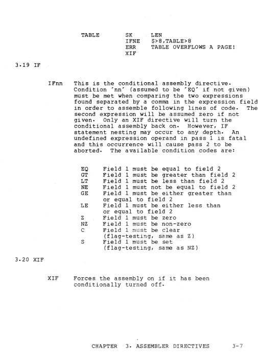
3.19 IF
3.20 XIF
IFnn
TABLE SK
IFNE ERR XIF
LEN
$>8,TABLE>8
TABLE OVERFLOWS A PAGE!
This is the conditional assembly directive.
Condition 'nn' (assumed to be 'EQ' if not given) must be met when comparing the two expressions found separated by a comma in the expression field in order to assemble following lines of code. The second expression will be assumed zero if not
given. Only an XIF directive will turn the conditional assembly back on. However, IF statement nesting may occur to any depth. An undefined expression operand in pass 1 is fatal and this occurrence will cause pass 2 to be aborted. The available condition codes are:
EO Field 1 must be equal to field 2
GT Field 1 must be greater than field 2 LT Field 1 must be less than field 2
NE Field 1 must not be equal to field 2 GE Field 1 must be either grea ter than
or equal to field 2
LE Field 1 must be either .less than or equal to field 2
Z Field 1 must be zero NZ Field 1 must be non-zero C Field 1 must be clear
(flag-testing, same as Z ) S Field 1 must be set
(flag-testing, same as NZ)
XIF Forces the assembly on if it has been conditionally turned off.
[image:22.612.60.565.66.771.2]CHAPTER 4. ASSEMBLER MACROS
Assembler MACROS are opcode mnemonics which directly result in the generation of a sequence of machine instructions.
4.1 HL
HL (exp)
4.2 DE
DE (exp)
4.3 BC
BC (exp)
The HL macro generates the load H register and load L register
instructions necessary to place the value of the expression field in the H and the L registers properly so that a
load to or from memory will use that address i.e. H contains the MSB and L
contains the LSB. The HL macro
generates four bytes of object code. For example:
OOPS EQU 02005
HL OOPS
generates the following code:
066 005 056 004
The DE macro works the same as the HL macro except i t loads the D and E registers instead of Hand L.
The BC macro works the same as the HL macro except i t loads the Band C registers instead of Hand L.
4.4 MEMORY STORE
MS (r) (*){ exp) The Memory Store macro allows the user to store a given register into a given memory location. Placing an * in front of the expression causes the H-register to be loaded as well as the L. The expansion is as follows:
4.5 MEMORY LOAD
LL LH LM{r)
(exp)
(exp»8 if * is present
ML{r) (*)(exp) The Memory Load macro works the same as the Memory Store (MSr) macro with the exception that the register is loaded from memory rather than being stored into memory.
4.6 SHIFT RIGHT NUMBERIC
SRN (exp)
4-2 DOS ASSEMBLER 5
The Shift Right Numeric macro allows the user to generate SRC instructions the number of times specified in the
expression field. The expression must be defined in pass one and must have a value between zero and seven. For example:
SRN 3
will generate the following code:
4.7 SHIFT LEFT NUMERIC
SLN (exp) The Shift Left Numeric macro works the same as the SRN macro with the exception that SLC instructions (002) are
generated.
CHAPTER 5. OPERATING PROCEDURES
The DOS command requesting execution of the Version 5 ASSEMBLER should be as follows:
ASM source ( ,object( ,entryp)) (i (D) (L) (X) (F) (I) (G))
where each pair of parentheses and their content is optional.
5.1 PARAMETERIZATION
.The first file spec (which ~ required) is the source file, the second file specification is for the object file, and the third file specification is for the entry point file. Each of these three files must be physically different. The source file has a default extension of TXT. The object file, if not given, is assumed to have the same name as the source file and has a default extension of ABS. The entry point file, if required and not
gi ven, is a ssumed to ha ve the same name as the source fi Ie with a default extension of EPT. The entry point file is written after pass one only if entry points have been declared in the program. The EPT file is written in a compressed symbolic format which can
be INCLUDED by a later assembly to provide a program linking capability.
The characters on the command line following the semicolon specify output options. The character L will cause the output to be listed on a Servo printer, if one is on-line. Otherwise, L produces a listing on the local printer. If the character X appears, a cross-reference map will be listed on the Servo or local printer (as above). X may appear in the command line without L if a cross-reference table but no program listing is desired. The character D signifies that the output should be displayed on the 2200 CRT, and the remaining valid characters
instruct the ASSEMBLER to turn on their respecti ve Ii sting control flags (see Section 3.17). If neither L nor X appear as parameters, no printed output is produced. Assembly error messages are
displayed on the CRT regardless of which options are specified.
5.2 EXECUTION-TIME COMMANDS
During the ASSEMBLER pass one and pass two, two
execution-time commands may be invoked. Depressing the DISPLAY key will prevent the 2200 CRT screen from rolling up until the key is released. The KEYBOARD key may be used to terminate the
assembly and return to DOS.
5.3 ASSEMBLER PASS ONE
Initially the ASSEMBLER will validate the three file
specifications and the parameter string and will then request an 80-character heading if either the L or X parameter was specified. Next it wi 11 print i t s Version number and the maximum number of
labels it can handle in its dictionary. The ASSEMBLER will then read the source file and any INCLUDED files in order to build a dictionary containing all symbolic names used by the programmer and their equivalent octal value or address. A notation is printed as each INCLUDE is processed along with any lines which contain errors. At the end of pass one, one or more of the f9l1owing items will be printed:
1) Any pass one error flags
2) Dictionary overflow message if overflow occurred 3) Fatal error message if error occurred
4) Program Entry Points--name, value 5) List of undefined symbols
6) List of unused symbols
7) List of multiply defined symbols 8) PAB starting locations and lengths
5.4 ASSEMBLER PASS TWO
If no fatal pass one errors occurred, the ASSEMBLER will now write the entry point file, if required, and proceed into pass
two. Pass two is responsible for the actual generation of object code and.a program listing. However, if a cross-reference listing is to be generated, pass two will also write a reference file
(ASMXREF/SYS) which will contain all symbolic references made in
the program. .
5.5 CROSS-REFERENCE GENERATION
At the completion of pass two, the ASSEMBLER will call in overlay 1 if a cross-reference listing is desired. Overlay 1 uses DOS SORT to sort ASMXREF/SYS into the ordered file ASMSREF/SYS and produces from it a cross-reference table. The actual listing of references will contain the symbolic name preceded by its actual octal value, unless the name is undefined in which case it is preceded by asterisks. Following the symbolic name is a list of all line numbers at which that symbolic name was defined or
referenced. All definit~on lines are flagged with a leading asterisk while all Inclusions are noted by a trailing colon
followed by the Inclusion file character (see Section 3.1). For
example:
11304 'DECHL *32:A *32:B
0034i DISPL *24
00024 IDLE *197212 212 212
10176 INCHL 71 * 102 151 156
00007 MANY 21 :A *25:A 21:B *25:B
*****
ILDE 2135.6 ASSEMBLY ERRORS
The ERROR FLAGS produced by the 2200 ASSEMBLER during both passes are as follows:
5.5.1 D
5.5.2 I
5.5.3 E
5.5.4 U
5.5.5 F
5.5.6 P
The D flag means DIFFERENT DEFINITION. It is generated if an attempt has been made to define the label more than once without a trailing; mark. Generated in pass one only.
The I flag means INSTRUCTION MNEMONIC UNDEFINED. The instruction was not an acceptable instruction and a zero or 0377 is inserted for the
instruction.
The E flag means that an error has occurred in an EXPRESSION or some unrecognizable character
appeared in the wrong place. In this case, a zero is substituted for the expression or in whatever was unrecognizable if code generation was
expected.
The U flag means UNDEFINED LABEL. It is issued in pass two whenever a label is referenced and is not defined and it is issued in pass one when an
assembly directive (except DA or DC) is operating on an expression containing a label not yet in the dictionary {forward referencing}.
The F flag means FILE error. It can be issued in either pass when the ASSEMBLER'S limits for an inclusion are exceeded or when an INCLUDED file contains an END directive.
The P flag means PROGRAMMER PRODUCED. It is issued in both pa sses when an ERR directi ve is encountered.
APPENDIX A. INSTRUCTION REPERTOIRE
Notes: Opcodes shown without mnemonics are undefined. See Datapoint 2200 reference manual for further instruction definition.
OP OP
CODE MNEMONIC CODE MNEMONIC
000 040 DI
001 041
002 SLC 042
003 RFC 043 RTC
004 XXX AD <exp> 044
xxx
ND <exp>005 045
006 XXX LA <exp> 046 XXX LE <exp>
007 RET 047
010 SYNC 050 EI
011 051
012 SRC 052
013 RFZ 053 RTZ
014 XXX AC <exp> 054
xxx
XR <exp>015 055
016 XXX LB <exp> 056
xxx
LH <exp>017 057
020 BETA 060 POP
021 061
022 062
023 RFS 063 RTS
024 XXX SU <exp> 064 XXX OR <exp>
025 065
026 XXX LC <exp> 066 XXX LL <exp>
027 067
030 ALPHA 070 PUSH
031 071
032 072
033 RFP 073 RTP
034 XXX SB <exp> 074 XXX CP <exp>
035 075
036 XXX LD <exp> 076
037 077
OP OP
CODE MNEMONIC CODE MNEMONIC
100 LSB MSB JFC <exp> 140 LSB MSB JTC <exp>
101 INPUT 141
102 LSB MSB CFC <exp> 142 LSB MSB CTC <exp>
103 143
104 LSB MSB JMP <exp> 144
105 145
106 LSB MSB CALL <exp> 146
107 147
110 LSB MSB JFZ <exp> 150 LSB MSB JTZ <exp>
111 151 EX BEEP
112 LSB £-1SB CFZ <exp> 152 LSB MSB CTZ <exp>
113 153 EX CLICK
114 154
115 155 EX DECK1
116 156
117 157 EX DECK2
120 LSB MSB JFS <exp> 160 LSB MSB JTS <exp>
121 EX ADR 161 EX RBK
122 LSB MSB CFS <exp> 162 LSB MSB CTS <exp>
123 EX STATUS 163 EX WBK
124 164
125 EX DATA 165
126 166
127 EX WRITE 167 EX BSP
130 LSB MSB, JFP <exp> 170 LSB MSB JTP <exp>
131 EX COMl 171 EX SF
132 LSB MSB CFP <exp> 172 LSB MSB CTP <exp>
133 EX COM2 173 EX SB
134 174
135 EX COM3 175 EX REWND
136 176
137 EX COM4 177 EX TSTOP
OP OP
CODE MNEMONIC CODE MNEMONIC
200 ADA 240 NDA
201 ADB 241 NDB
202 ADC 242 NDC
203 ADD 243 NDD
204 ADE 244 NDE
205 ADH 245 NDH
206 ADL 246 NDL
207 ADM 247 NDM
210 ACA 250 XRA
211 ACB 251 XRB
212 ACC 252 XRC
213 ACD 253 XRD
214 ACE 254 XRE
215 ACH 255 XRH
216 ACL 256 XRL
217 ACM 257 XRM
220 SUA 260 ORA
221 SUB 261 ORB
222 SUC 262 ORC
223 SUD 263 ORD
224 SUE 264 ORE
225 SUH 265 ORH
226 SUL 266 ORL
227 SUM 267 ORM
230 SBA 270 CPA
231 SBB 271 CPB
232 SBC 272 CPC
233 SBD 273 CPD
234 SBE 274 CPE
235 SBH 275 CPH
236 SBL 276 CPL
237 SBM 277 CPM
OP OP
CODE MNEMONIC CODE MNEMONIC
300 NOP 340 LEA
301 LAB 341 LEB
302 LAC 342 LEC
303 LAD 343 LED
304 LAE 344
305 LAH 345 LEH
306 LAL 346 LEL
307 LAM 347 LEM
310 LBA 350 LHA
311 351 LHB
312 LBC 352 LHC
313 LBO 353 LHD
314 LBE 354 LHE
315 LBH 355
316 LBL 356 LHL
317 LBM 357 LHM
320 LCA 360 LLA
321 LCB 361 LLB
322 362 LLC
323 LCD 363 LLD
324 LCE 364 LLE
325 LCH 365 LLH
326 LCL 366
327 LCM 367 LLM
330 LOA 370 LMA
331 LOB 371 U1B
332 LDC 372 LMC
333 373 LMO
334 LDE 374 LME
335 LDH 375 LMH
336 LDL 376 LML
337 LDM 377 HALT
APPENDIX B. MNEMONIC OPCODE REPERTOIRE
This appendix contains a list of all valid mnemonics which
can be used in the opcode field of the ASSEMBLER. Each mnemonic
is followed with a brief definition of its usage. Note that the
condition flip-flops which are specified as <c> may be specified as follows:
Carry
---
C or BZero
----
Z or ESign
----
S or L or NParity
--
PThe processor registers which are specified as <r> may be specified by the register name, i.e. A, B, C, D, E, H, L or M (if Memory Ref).
AC AC<r> AD AD<r> ALPHA
BC BETA CALL CF<c> CT<c>
CP CP<r> DA DC DE
DI EI END
EQU
ERR
DESCRIPTION
Add with Carry Immediate Instruction Add with Carry Register Instruction Add Immediate Instruction
Add Register Instruction
Select Alpha Mode Instruction
Load Band C Macro
Select Beta Mode Instruction Subroutine Call Instruction
Conditional Subroutine Call Instruction Conditional Subroutine Call Instruction
Compare Immediate Instruction Compare With Register Instruction Define Address Directive
Define Constant Directive
Load 0 and E Macro
Disable Interrupt Instruction Enable Interrupt Instruction End Source Code Directive Equivalence Directive Produce Error Directive
3.8 3.7 4.2
3.13 3.2 3.18
OPCODE EX HALT HL IF<nn> INCLUDE INPUT JF<c> JMP JT<c> L<r> L<r><r> LIST LOC ML<r> MS<r> ND ND<r> NOP OR OR<r> ORG POP PUSH RET RF<c> RT<c> RPT SB SB<r> SET SKIP SLC SLN SRC SRN DESCRIPTION
External I/O Instruction Processor Halt Instruction Load Hand L Macro
Conditional Assembly Directive Source File Inclusion Directive
I/O Input Instruction
Jump on False Condition Instruction Jump Instruction
Jump on True Condition Instruction Load Immediate " Instruction
Load from Register Instruction Listing Control Directive
Location Counter Manipulative Directive Memory Load Macro
Memory Store f<1acro
And Immediate Instruction And with Register Instruction
No Operation Instruction Or Immediate Instruction Or with Register Instruction
SECTION 4.1 3.19 3.1 3.17 3.9 4.5 4.4
PAB Origination Directive 3.10
Pushdown Stack Manipulation Instruction Pushdown Stack Manipulation Instruction Subroutine Return Instruction
Conditional Subroutine Return Instruction
Conditional Subroutine Return Instruction
Repeat Source Line Directive 3.12
Subtract with Borrow Immediate Instruction Subtract with Borrow Register Instruction Address Counter Manipulation Directive 3.3
Address/Location Counter Directive Shift Left Circular Instruction Shift Left Numeric Macro
Shift Right Circular Instruction Shift Right Numeric Macro
3.4
4.7
4.6
OPCODE
SU SU<r> SYNC TM TP
USE XIF XR XR<r>
DESCRIPTION
Subtract Immediate Instruction Subtract Register Instruction Processor Sync Instruction Tab Page Maybe Directive Tab Page Directive
PAB Manipulation Directive
End Conditional Assembly Directive Exclusive Or Immediate Instruction Exclusive Or Register Instruction
SECTION
3.6 3.5
3.11
APPENDIX C. EXTERNAL COMMAND REPERTOIRE
MNEMONIC SIGNAL ADDRESS DESCRIPTION
ADR Address All Select New Device
BEEP
BSP
CLICK
COMl
COM2
COM3
COM4
DATA
DECKl
DECK2
RBK
REWIND
SB
SF
STATUS
TSTOP
Command 1
Command 2
Command 3
Command 4
Sense Data
All
0360
All
All
All
All
All
All
0360
0360
0360
0360
0360
0360
Sense Status All
0360
Activate Tone Producing Mechanism
Back Up One Record
Activate Click Producing Mechanism
Output a Control Function
Output a Control Function
Output a Control FUnction
Output a Control FUnction
Connects Device Data to Input Lines
Select Cassette Deck 1
Select Cassette Deck 2
Enable Read Circuitry and Forward Motion
Rewind The Selected Deck
Slew Backward Motion
Slew Forward Motion
Connects Device Status to Input Lines
Stop Any Deck Motion
MNEMONIC SIGNAL ADDRESS DESCRIPTION
WBK
--
\ 0360 Enable Write Circuitry andForward Motion
WRITE Write Strobe All Indicates Output Data
\
Avai labi Ii ty
APPENDIX D. OBJECT FILE FORMAT
The object file created by the ASSEMBLER has a system loader object format (see DOS User's Guide, Part IV, Sections 3.1 and 3.2) :
Logical Record Number
LRN 0 (RIB)
LRN 1 (RIB COPY)
LRN 2
Byte # Description
0 Physica 1 File Number
1 Logical Record Number (LSB) 2 Logical Record Number (~-1SB )
3 0377
4 Segment Descriptor 1 5
6 Segment Descriptor 2
2N+2 Segment Descriptor N 2N+3
2N+4 0377 2N+5 0377
o
1 2
3
4
5 6
7
8
9
n+9 n+10 n+ll n+12
Physical File Number
Logical Record Number (LSB) Logical Record Number (MSB)
o -
indicating data blockStarting address of block (LSB) Starting address of block (MSB) One's complement of LSB of
starting address
One's complement of MSB of starting address
Block length (n) Beginning of data
o -
Next data blockStarting address of block (LSB) Starting address of block (MSB) One's complement of LSB of
LRN 3
LRN N
D-2 DOS ASSEMBLER 5
starting address
n+13 One's complement of MSB of starting address
n+14 Block length (m)
n+15 Beginning of block data
n+m+15 0 - Next da ta block
o
1
2
3
o
0377 - End of Record
Physical File Number
Logical Record Number (LSB) Logical Record Number (MSB)
o -
Next data blocko -
Last data block Transfer address (LSB) Transfer address (MSB)One's complement of the LSB of the transfer address
One's complement of the MSB of the transfer address
APPENDIX E. SAMPLE PROGRAM
The following pages contain a sample assembly language
program to 'give the reader a better understanding of the output he will see from the ASSEMBLER. Due to its tutorial nature, the
program itself does not do anything useful. However, an example of every instruction, expression, directive, and Assembler Macro is given along with examples of how various errors are flagged and treated.
,
. ,
E-2 DOS ASSEMBLERS
(
PAGE ASM5SMPLlTXT APPENDIX E. SAMPLE ASSEMBLY LANGUAGE PROGRAM
DOSAStvJ5 3. 1 568 LABELS
INCLUSION A: ASM5TST2/TXT
E 17 .A 4DOGS BQU $ THIS IS AN ERROR DURING INCLUSION U 19.A HICUPS EQU MANY THIS WILL PRODUCE A 'D' ERROR
F 43.A END ERROR! THIS IS AN INCLUDED LINE
INCLUSION B: ASM5TST2ITXT
E 17 .B 4DOGS EQU $ THIS IS AN ERROR DURING INCLUSION D 19.B HICUPS EQU MANY THIS WILL PRODUCE A 'D' ERROR
F 43.B END ERROR! THIS IS AN INCLUDED LINE
D 287. TABLE DC o 1 0 , 020 ,030 THREE CODE BYTES ARE GENERATED t: 306. DC 'PROGRAM XXXXX VERSION " 'O'+VER
E 313. DC 'PROGRAM XXXXX VERSION ','O'+VER
E 320. lDOG LA 5
E 321, 2DOG LA DOGGIE ONLY ONE ERROR FLAG WILL BE SEEN 322. QUICK% DC 'INVALID DUE TO TRAILIN~ ~ MARK' ,
E
E 332. SLN 25
E 341- DA **3+TABLE
ERRORS: DEUF
PROGRAM ADDRESS BLOCKS: 007314 IABSOLUTEI LTH=000673 010000 /DATAI LTH=000364 012000 /CODEI LTH=OOOOOO 014000 IBUFFER/ LTH=000360 014000 IINIT! LTH=000137
PRIMARY TRANSFER ADDRESS: 014000
ENTRY POINTS: 014000 BUFFER 010006 PNTR 010176 INCHL
MULTIPLE DEFINITIONS: SEC MANY PNTR DECHL
UNDSFINED LABELS: DOGGIE
PAGE 2 1. 2. 3. 4. 5. 6. 7. 6. 9. 10. 11. 12. 13. 14. 15. 16. 17. 18. 19. 20. 21. 22. 23. 24. 25. ASM5SMPLlTXT
26. 000341 27. 000341
28. 29. 30. 3" 32. 33. 34. 35. 36. 37. 38. 39. 40. 41-42. 43. 44. 45. 000252 000125 00037'7 010000 012000 014000 014000
APPENDIX E. SAMPLE ASSEMBLY LANGUAGE PROGRAM
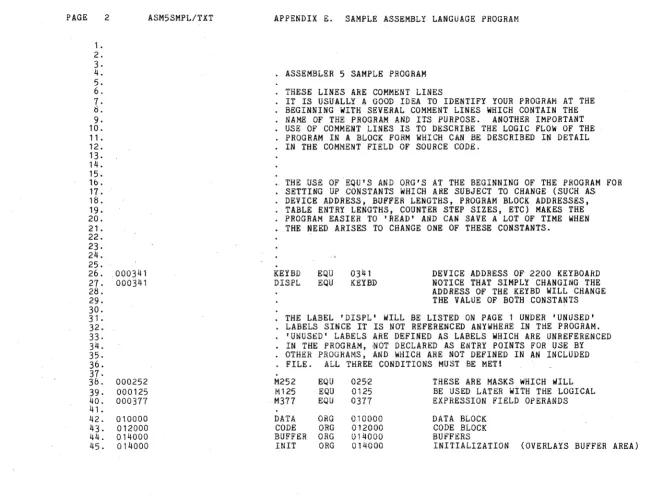
ASSEMBLER 5 SAMPLE PROGRAM
THESE LINES ARE COMMENT LINES
IT IS USUALLY A GOOD IDEA TO IDENTIFY YOUR PROGRAM AT THE BEGINNING WITH SEVERAL COMMENT LINES WHICH CONTAIN THE NAME OF THE PROGRAM AND ITS PURPOSE. ANOTHER IMPORTANT USE OF COMMENT LINES IS TO DESCRIBE THE LOGIC FLOW OF THE PROGRAM IN A BLOCK FORM WHICH CAN BE DESCRIBED IN DETAIL IN THE COMMENT FIELD OF SOURCE CODE.
THE USE OF ·EQU'S AND ORG'S AT THE BEGINNING OF THE PROGRAM FOR SETTING UP CONSTANTS WHICH ARE SUBJECT TO CHANGE (SUCH AS DEVICE ADDRESS, BUFFER LENGTHS, PROGRAM BLOCK ADDRESSES, TABLE ENTRY LENGTHS, COUNTER STEP SIZES, ETC) MAKES THE PROGRAM EASIER TO 'READ' AND CAN SAVE A LOT OF TIME WHEN THE NEED ARISES TO CHANGE ONE OF THESE CONSTANTS.
KEYBD EQU 0341
DISPL EQU KEYBD DEVICE ADDRESS OF 2200 KEYBOARD NOTICE THAT SIMPLY CHANGING THE ADDRESS OF THE KEYBD WILL CHANGE THE VALUE OF BOTH CONSTANTS
THE LABEL 'DISPL' WILL BE LISTED ON PAGE 1 UNDER 'UNUSED' LABELS SINCE IT IS NOT REFERENCED ANYWHERE IN THE PROGRAM.
'UNUSED' LABELS ARE DEFINED AS LABELS WHICH ARE UNREFERENCED IN THE PROGRAM, ,NOT DECLARED AS ENTRY POINTS FOR USE BY OTHER PROGRAMS, AND wHICH ARE NOT DEFINED IN AN INCLUDED FILE. ALL THREE CONDITIONS MUST BE MET!
M252 EQU 025--2 THESE ARE MASKS WHICH WILL M125 EQU 0125 BE USED LATER WITH THE LOGICAL M377 EQU 0377 EXPRESSION FIELD OPERANDS
DATA ORG 010000 DATA BLOCK CODE ORG 012000 CODE BLOCK BUFFER ORG 014000 BUFFERS
[image:47.792.47.704.68.563.2]PAGE 3 ASM5SHPL/TXT APPENDIX E. SAMPLE ASSEMBLY LANGUAGE PROGRAM
46. + THIS WILL FORCE A NEW LISTING PAGE 47.
48.
49. 007314 SET 007314 NOTICE THAT THE ABSOLUTE PAB
50. WILL IMPLICITLY BE USED HERE
51-52. 007400 TP THIS WILL FORCE A NEW MEMORY PAGE 53.
54. 007400 SK 200 IF WE HAVE A TABLE 60 BYTES IN LENGTH
55. WHICH WE ARE COUNTING ON AS BEING
56. ON ONE PAGE (PAGE-DEPENDENT), WE
57. CAN USE A TM DIRECTIVE LIKE THIS
58. 010000 TM 60 TO MAKE SURE THAT THE ENTIRE TABLE
59. WILL EITHER FIT ON THE CURRENT MEMORY
-_ .. ~.~ ._- " ... -. - _.-.. _--- ----... -~-;--....
----
.. ---""-..,.... ...-.
PAGE 4 ASM5SMPLITXT APPENDIX E. SAMPLE ASSEMBLY LANGUAGE PROGRAM
61. +
62. THE FOLLOWING PORTION OF CODE IS A SAMPLE 2200 1/0 ROUTINE 63.
64. 010000 006 341 LA KEYBD PICK UP AN OCTAL 341 IN THE A-REGISTER
65. 010002 121 EX ADR AND ADDRESS THE KEYBOARD
66. 010003 101 WAITI INPUT GET THE DEVICE STATUS IN A
67. 010004 044 002 ND 2 CHECK FOR TriE READ READY BIT
68. 010006 150 003 020 JTZ WAITI AND WAIT UNTIL IT IS SET TO A 1
69. 010011 125 EX DATA SWITCH FROM STATUS TO DATA ON THE
70. 2200 INPUT LINES
71- 010012 101 IN AND INPUT THE ACTUAL DATA CHARACTER
72. 010013 066 056 056 020 HL CHAR POINT HAND L TO MEMORY LOCATION 'CHAR'
73. 010017 370 LMA AND STORE THE CHARACTER WHICH IS IN A
74. 010020 106 176 020 CALL INCHL POINT HAND L TO THE NEXT MEMORY LOCATION
75. 010023 377 HALT STOP THE 2200
76. 010024 151 EX BEEP AND BEEP WHEN 'RUN' IS PRESSED
77. NOTtCE THE FOLLOWING TWO LINES AND THE SEPARATE USES OF 'STATUS'
78. 010025 123 EX STATUS SWITCH BACK TO THE DEVICE STATUS
79. 010026 101 STATUS IN AND GET THE NEW ~TATUS
80. 010027 012 SRC CHECK FOR DISPLAY READY BY POSITIONING
8l. THE READY BIT SUCH AS TO SET THE CARRY FLAG
82. 010030 100 026 020 JFC STATUS AND WAIT FOR THE BIT TO BECOME NON-ZERO 83. BELOW ARE THREE MANNERS IN WHICH TO GENERATE THE 5 BYTES OF
84. CODE WHICH ARE REQUIRES TO STORE THE A-REGISTER IN 'CHAR' 85. 010033 066 056 056 020 370 MSA' ·CHAR YOU CAN USE A SINGLE MACRO 8b.
87. 010040 066 056 056 020 HL CHAR YOU CAN USE A MACRO
88. 010044 370 LMA AND A 2200 MNEMONIC
89.
90. 010045 056 020 LH CHAR>8 YOU CAN ALSO USE THREE
91. 010047 066 056 LL CHAR INDEPENDENT 2200
92. 010051 370 LMA INSTRUCTION MNEMONICS
93.
94. 010052 127 EX WRITE OUTPUT THE CHARACTER IN' A
95. 010053 104 053 020 JMP $ THIS WILL HANG IN AN ENDLESS LOOP! 96. NOTICE THAT THE STORAGE ARRAY CALLED 'CHAR' MAY BE INTERSPERSED
97. • WITH THE CODE PROVIDING THAT NO ATTEMPT IS MADE TO EXECUTE IT
98. 010056 CHAR SK 80 THIS WILL ALLOW 80 MEMORY LOCATIONS
99. TO BE USED FOR THE ARRAY BUT NO
100. DATA WILL BE LOADED INTO THE ARRAY
101.
102.
*
FORCE THE FOLLOWING ROUTINE TO BE PRINTED ON ONE PAGE103. INCHL -- INCREMENT HAND L BY 1
104.
105. 010176 306 INCHL· LAL LOAD THE L-REG INTO THE A-REG
lOb. 010177 004 001 AD ADD ONE TO THE A-REG
107. 0102{)1 360 LLA LOAD THE L-REG BACK FROM THE A-REG
108. 010202 305 LAH . LOAD THE H':"REG INTO THE A-REG
109. 010203 014 000 AC 0 ADD 1 ONLY IF L OVERFLOWED
\
PAGE 5
112. 113. 114. 115. 116. 117 •
11 &.
119. 120. 121. 122. 123. 124. 125. 126. 127. 128. 129. 130. 131. 132. 133. 134. 135. 136. 136. 136. 137. 138. 014000 014000 010000 010000 014120 014120 010002 010002 014240 014240 010004 010004 010006 010006 010010 010012 ASM5SMPL/TXT
000 030
120 030
240 030
000 030 120 030 240 030
APPENDIX E. SAMPLE ASSEMBLY LANGUAGE PROGRAM
+
NOTICE THAT THE ASSEMBLER KEEPS TRACK OF THE ADDRESS COUNTER WHEN SWITCHING BETWEEN PABS TO GENERATE TABLES
.
BUFFER* USE BUFl SK
USE PNTR* DA
USE BUF2 SK
U&E DA USE BUF3 SK
USE DA BUFFER SO DATA BUFl BUFFER 80 DATA BUF2 it SO it BUF3
SET UP 3 BUFFERS IN ONE BLOCK
POINT TO THE 3 BUFFERS
RETURN TO THE BUFFER BLOCK
IMPLIED USAGE OF 'BUFFER' PAB
IMPLIED USAGE OF 'DATA' PAB
• NOTICE THAT A SIMPLIER MANNER IN WHICH TO GENERATE THE POINTER TABLE FOLLOWS AND THAT THIS PROCEDURE WILL NOT GENERATE
DICTIONARY ENTRIES WHICH MAY NOT OTHERWISE BE NEEDED.
PNTR:: EQU $
RP.'J: 3
NOTICE THAT ALL REFERENCES TO 'PNTR' WILL USE THE CURRENT ADDRESS
DA $-PNTR/2itSO+BUFFER
DA $-PNTR/2*SO+BUFFER DA $-PNTR/2it80+BUFFER
[image:50.791.25.748.62.518.2]PAGE 6 ASM5SMPLITXT 139. 140. 141. 142. 143. 144. 145. 146.
147. 014000 148.
149. 014000 066 000 056 150. 014004 070
151. 014005 066 040 056 152. 014011 026 077 153. '014013 307
154. 014014 106 176 020 155. ' 014017 335
156. 014020 346 157. 014021 ' 060 158. 014022 370
159. 014023 106 176 020 160. 014026 070
161. 014027 302 162. 014030 024 001 163. 014032 320 , 164. 014033 353 165. 014034 364
166. 014Q35 100 013 030 '167.
1'68. 169. 170. 171. ' 172. 173. 174.
000
030
APPENDIX E. SAMPLE ASSEMBLY LANGUAGE PROGRAM
+
ANOTHER FEATURE OF USING PAB'S IS THAT THE ASSEMBLER CAN KEEP TRACK OF THE USAGE OF THE SAME BLOCK OF CODE WITH TWO DIFFERENT PAB'S FOR USE IN SETTING UP BUFFERS, ETC. WHICH DO NOT ACTUALLY LOAD MEMORY (THEY GENERALLY ARE SKIPS) AND THEN OVERLAY THESE BUFFERS WITH ONE-SHOT INITIALIZATION PROCESSES.
USE OVERLAY THE BUFFERS
• THIS START CODE HL
PUSH HL LC LAM CALL LDH LEL POP LMA CALL PUSH LAC SU LCA' LHD LLE JFC IN IT MOVES THE
0000 ROUTINE 'INT' INTO LOW CORE (LOC'N 0000) POINT TO DESTINATION ADDRESS
MOVE INT INTEND-INT INCHL INCHL MOVE
AND PUSH IT ON THE STACK POINT TO SOURCE ADDRESS ' C = ROUTINE LENGTH
PICK UP A BYTE
BUMP THE SOURCE ADDRESS AND STORE IT IN D AND E
GET THE DESTINATION ADDRESS AND STORE THE BYTE ' BUMP THE DESTINATION ADDRESS
AND STORE IT ON THE STACK MOVE THE COUNTER FROM C TO A DECREMENT THE COUNT BY ONE RELOAD C WITH THE COUNTER
RESTORE SOURCE A~DRESS
LOOP UNTIL ENTIRE ROUTINE IS MOVED
PAGE 1'75. 176. 177. 17tL 179. 100.
1 b 1.
Hl2. 103. H$4. H15. 106. 107. 1I:HL Hly. 190. 19" 192 . 193. 194. 195. 196. 197. 19b. 199. 200. 201 . 202. 203. 204. 205. 206. 207. 20b. 209. 210. 211. 212. 213. 214. 215. 216. 217. 210. 219. 220. 22,. 222. 223. 224. 225. 22b. 227.
7 ASM5SMPL/TXT
014040 OOOOOOL OOOOOOL 040 000001L 020 000003
000002L 006 000 000004L 004 001 000006L 074 372 000010L 100 037 000 000013L 066 003 056 000 000017L 300
000020L 300 000021L 300 000022L 026 004 000024L 370 000025L 302 000026L 024 001 000030L 300
000031L 110 026 000 000034L 030
000035L 050 000036L 007 00003"{L 250
000040L 066 003 056 000 370
000045L 066 075 307 000050L 004 001 000052L 044 003 000054L 026 002 000056L 110 024 000 000061L 006 000 000063L 370
000064L 066 076 307 000067L 004 001 000071L 370
000072L 104 034 000 000075L 000
000076L 000 014137 000076
APPENDIX E. SAMPLE ASSEMBLY LANGUAGE PROGRAM
+
THE FOLLOWING ROUTIN£ 'INT' IS DESIGNED TO BE MOV~D:INTO LOw CORE PRIOR TO ACTUAL EXECUTION BY SOME TYPE OF A RELOCATING PROGRAM AS SEEN ABOVE. THE ROUTINE 'INT' IS AN INTERRUPT DRIVEN CLOCK PROGRAM WHICH KEEPS TIME IN LOCATION 'SEC' IN ONE SECOND STEPS DERIVED FROM THE 2200'S 1 MILLISECOND INTERRUPT CLOCK. PLEASE NOTICE THAT THE ROUTINE MAKES USE OF A TIMING LOOP AND NOP'S IN ORDER TO CONSUME A PRECISE AMOUNT OF TIME (THAT BEING 116.8 MICROSECONDS) REGARDLESS OF WHETHER UPDATING ONE BYTE OR THREE. THIS IS NECESSARY IF MULTIPLE TIME-CRITICAL 1/0 TASKS ARE TO BE HANDLED AT EACH INTERRUPT TIME.
INT
MSEC
EQU LOC . DI BETA EQU LA AD CP JFC HL NOP NOP NOP LC IDLE LMA
LAC TIMEIT SU
NOP JFZ GOBACK ALPHA
EI RET INT2 XRA MSA NOTICE THE
I"ILA AD ND LC JFZ LA LHA MLA AD LMA JMP QSEC DC SEC DC INTEND LOC SEC= EQU
:$ 0000 $+1 0000 1 250 INT2 MSEC 4 TIMEIT -MSEC
USE OF THE * IN QSEC 1 3 2 IDLE
o
SEC 1 GOBACK o o"
.'ji-1-INTTHIS IS THE LOADING ADDRESS
WHEREAS THIS IS THE EXECUTION ADDRESS DISABLE INTERRUPTS
SWITCH TO BETA MODE REGISTERS MILLISECOND TIMER
LOAD THE MILLISECOND TIMER AND BUMP IT BY ONE CHECK FOR 1/4 SECOND VALUE
AND JUMP IF ATTAINED POINT HL TO 'MSEC'
THESE NOP'S ARE FOR TIMING!
SET TIMING LOOP COUNT STORE THE NEW TIMER VALUE GET THE LOOP COUNT
DECREMENT THE COUNT USED FOR TIMING CYCLE IN TIMING LOOP
RETURN TO THE ALPHA MODE REGISTERS ENABLE THE INTERRUPT SYSTEM
RETURN TO INTERRUPTED PROGRAM LOAD THE A-REGISTER WITH ZEROES CLEAR THE MILLISECOND TIMER THE l'1SA AND MLA MACROS
PICK UP THE QUARTER SECOND TIMER BUMP IT
AND FORCE MODULO 4 (SAME AS CP 4 HERE) SET UP TIMING LOOP COUNTER
GO BACK IF NOT A FULL SECOND
CLEAR THE QUARTER SECOND TJMER PICK UP THE ACCUMULATED SECONDS
BUMP IT AND STORE IT THEN RETURN
THIS IS THE ACTUAL 1 SECOND TIMER THIS IS THE END OF THE ROUTINE
PAGE t3 22B. 229. 230. 231. 232. 233. 234. 235. 236. 237. 238. 239. 240. 241. 242. 243. 244. 245. 246. 247. 24!L 249. 250. 251. 252. 253. 254. 255. 250. 257. 25~. 259. 260. 201. 262. 263. 264. 265. 266. 267. 268. 269. 270. 271. ASM5SMPL/TXT 010014
010014 000 002 000 004 000
010030 300
010031 001 002 003 004 005
010036 005 004
APPENDIX E. SAMPLE ASSEMBLY LANGUAGE PROGkAM
+
HERE ARE A FEW E'AMPLES OF CONDITIONAL ASSEMBLY IF STATEMENTS
DATA
TABLE . NOW
USE LIST DA TEST TO
IFNE ERR XIF
-G
01000,02000,03000,04000,05000,06000 MAKE SURE THAT THE ABOVE 'TABLE' IS
$>d,TABLE>8 ALL ON THE SAME PAGE
******* TABLE ERROR *******
MASK TESTING CAN ALSO BE DONE
IF M252.0.M125,M377
NOP THIS WILL BE ASSEMBLED
XIF
IFZ M252.A.M125 IFGT 5,4
IFS M377
CONDITIONAL ASSEMBLY TESTS MAY BE NESTED TO ANY DEPTH. IN SUCH A CASE, THE CODE WILL ONLY BE ASSEMBLED IF ALL PRECEEDING TESTS ARE TRUE. NOTICE THAT ALTHOUGH THE THREE PRECEEDING IF'S ARE TRUE AS CAN BE SEEN BY THE ASSEMBLY OF THIS DC STATEMENT,
DC 1,2,3,~,5
THE FOLLOWING IF IS NOT SATISFIED AND THEREFORE THE LINES OF CODE WHICH FOLLOW IT WILL NOT BE EXAMINED BY THE STATEMENT SCANNER.
IFLE 010,7
SKIP 4 ALL OF THESE STATEMENTS ARE IGNORED HALT
ERR
DC 0,0
DO NOTE THAT SINCE THE SCANNER IS ONLY LOOKING FOR AN XIF AT THIS TIME THAT ALTHOUGH THE FOLLOWING IF'S ARE SATISFIED ON A LINE FOR LINE BASIS, THEY WILL BE IGNORED AND WILL NOT ALLOW ASSEMBLY OF THE CODE wHICH FOLLOWS THEM.
IFEQ 2,2 DC 2
IF 3,2*1+1 DC 3 NOP
PAGE 9 272. 273· 274. 275. 276.
E 17.A 010040
F 43.A 277. 27(j .. 279. 2(j0. 281. 1.B 2.B 3·B 4.B 5.B b.B 7.B (j.B 9.B 10.B 11.B 12.B 13.B 14.B 15.B 16.B
E 17.B 010040
1!l.B
19.B 000007 20.B
21.B 22.B
23.B 000007 24.B 25.B 26.B 27.B 2b.B 29.B ASM5SMPLITXT
30.B 011304 31.B 32.B 33.B 34.B 35.B 36.b 3'7.B 3d.B 39.B 40.B 41.B 42.B
APPENDIX E. SAMPLE ASSEMBLY LANGUAGE PROGRAM
+
INCLUDE TEXT FROM ANOTHER FILE
LIST -I DO NOT LIST INCLUDED LINES INC ASM5TST2
4DOGS EQU $ THIS IS AN ERROR DUllING INCLUSION END ERROR! THIS IS AN INCLUDt:D LINE
NOW INCLUDE THE SMIE TEXT BUT LIST IT
LIST I
INC ASM5TST2 THIS INCLUSION USES SUFFIX 'B'
NOTICE THAT THIS IS LINE NUMBER 4 OF AN INCLUDED FILE. THE INCLUSION LEVEL IS INDICATED BY THE TRAILING CHARACTER OF THE LINE NUMBER WHICH WILL START WITH AN 'A' AND INCREMENT THROUGH THE ALPHABET AS EACH INCLUSION IS MADE REGARDLESS OF WHETHER THE INCLUDED LINES ARE LISTED OR NOT.
ALL OF THE INCLUSION FILE INFORMATION LINKING EACH INCLUSION OF EACH FILE wITH AN ALPHABETIC CHARACTER IS GIVEN ON PAGE 1 OF THIS LISTING IN SEQUENrIAL ORDER.
NOTICE THAT THE CROSS-REFERENCE MAP WILL FLAG ALL REFERENCES WITH THEIR FILE IDENTIFICATION CHARACTER.
4DOGS EQU $
HICUPS EQU MANY
MANY: EQU 7
DECHL= EQU 011304
THIS IS AN ERROR DURING INCLUSION
THIS WILL PRODUCE A 'D' ERROR SINCE IT IS NOT SPECIFIED AS MULTIPLY DEFINABLE.
ALL lNCLUDED ITEMS MUST HAVE THE TRAJLING = MARK IF THEY MIGHT POSSIBLY BE DEFINED MORE THAN ONCE, SUCH AS IN THE CASE OF INCLUDED SUBROUTINES WHICH ALL USE COMMON OPERATING SYSTEM ROUTINES
HEHE IS SUCH A CRITTER
THE INCLUDED FILE IS ALSO AN INTEGRAL PART OF THE ASSEMBLER'S ENTRY POINT / EXTERNAL REFERENCE 'LINKING' CAPABILITY. THE ONLY MANNER IN WHICH THE ENTRY POINT fILE CAN BE USED IS BY AN INCLUSION IN AN OVERLAY~D PROGRAM'S SOUR~E fILE.
PAGE 10
F 43.B 44.B 45.B 40.B 47.B
ASM5SMPLITXT APPENDIX E. SAMPLE ASSEMBLt LANGUAGE 2ROGRAM
END ERROR! THIS IS AN INCLUDED LINE
PAGE 11 E 2b2. 2b3. 284. 2b5. 286. 2tH. 2bl:L 289. 290. 291. 292. 293. 294. 295. 296. 297. 29b. 299. 300. 301. 302. 303. 304. 305. 306. 307. 3Ub. 309. 310. 311 . 312. ASM5SMPLlTXT 010040 010043 010050 010055 010062 010067 010074 010101 010106 010107 010114 010121 010126 010133 010140 010142 010147 010154 000003 010155 010162 010167 010174 010201 010204 010211 010216 010223 010230
010 020 030
124 110 111 123 040 115 125 114 124 111 055 103 110 101 122 101 103 124 105 122 040 115 105 123 123 101 107 105 040 111 123 040 107 117 117 104
102 105 103 101 125 123 105 105 101 103 110 105 130 120 122 105123123111117 116 123 124 101 122
124 123
127 111 124 110 101 123 124 122 111 116 107
120 122 117 107 122 101 115 040 130 130 130 130 130 040 126 105 122 123 111 117 116 040 063
120 122 117 107 122 101 115 040 130 130 130 130 130 040 126 105 122 123 111 117 116 040 060 000
313. 010234 120 122 117 107 122
APPENDIX E. SAMPLE ASSEMbLY LANU~AGE PBOUHAM
+
NOW A MULTIPLE DEFINITION OF A PREVIOUS LABEL WHERE NO TRAILING EQUAL (=) IS USED PRODUCES AN ERROR IN PASS ONE (SEE PAGE ONE)
TABLE
*
DC010,020,030 THREE CODE BYTES ARE GENERATED HERE IS AN EXAMPLE OF THE SPECIAL DC STRINGS
LIST G
DC 'THIS MULTI-CHARACTER MESSAGE IS GOOD'
DC 'BECAUSE' ,'EACH' ,'EXPRESSION' ,'STARTS'
DC 'WITH' ,'A' ,'STRING'
A GOOD MANNER IN WHICH TO CHANGE A NUMBER wITHIN A DISPLAY MESSAGE WITHOUT SEARCHING FOR THE ACTUAL DC STATEMENT COULD BE HANDLED FROM AN EQU AT THE START OF THE PROGRAM.
VER EQU 3 PROGRAM VERSION NUMBER
AND IMBEDDED WITHIN THE PROGRAM WOULD BE THE FOLLOWING: DC 'PROGRAM XXXXX VERSION' ,VER+'O'
HOWEVER, THIS WILL PRODUCE AN ERROR:
DC 'PROGRAM XXXXX VERSION' ,'O'+VER
THE ASSEMBLER WILL PRINT ALL ERROR LINES REGARuLESS JF TH~
LIST CONTROL FLAGS. HERE IS THE ABOVE EXAMPLE WITH THE 'G' FLAG TURNED OFF AND THE ERROR PRINTED.
LIST -G