SUBJECT
LEVELS 66, 68, AND DPS 8
MSU0500/0501 MASS STORAGE
UNIT OPERATION
General Description, Operation, and Maintenance Procedures for the MSU0500 and MSU0501 Mass Storage Units and Their Associated Mass Storage Processors
SPECIAL INSTRUCTIONS
This edition completely supersedes Revision 0 dated August 1977. It reflects the inclusion of the MSU0501 Mass Storage Unit and the associated Mass Storage Processors. Due to the extent of the revision, change bars and asterisks (denoting deletions) have not been used.
ORDER NUMBER
AY03, Rev. 1 December 1979
Preface
This reference manual contains performance specifications, and a description of the operator-accessible control panel switches and indicators and the oper-ating procedures necessary to enable personnel to operate and maintain the MSU0500/0501. Mass storage processor information is also included.
Contents
Introduction . . . . . . 1 3- Mass Storage Processor
MSU0500 Overview . . . 1 Components . . . 6
MSU0501 Overview . . . 2 4 l\rlSP0602/0603 Singie-Channel MSU0500/0501 Characteristics ... 3 Configurations. . . . 9
Advanced Data Integrity . . . 3 5 lvfSP0602/0603 Dual-Channel Efficient I/O Channel Utilization ... 3 Configurations. . . . .. 10
System Reliability
I
Availability . . . 3 6 MSP0605 Configurations ... 11Site Efficiency . . . 3 7 MSP0604/0607 Configuration ... 12
Options . . . 4 8 MSP0608/0609 Configuration ... 13
Controls and Indicators . . . 4 9 MSP8000 Configurations ... 14
Device Numbering . . . 4 10 MSP8001 Configurations ... 15
Operating Procedures . . . 5 11 Freestanding Mass Storage Power-Up Sequenee . . . 5 Processor Control Panel. ... 15
Power-Down Sequence . . . 5 12 Integrated Mass Storage Initialization . . . 5 Processor Control Panel. ... 16
Startup Sequence . . . 6
Operator Maintenance . . . 6
General Cleaning ... ~ . . . 6
Mass Storage Processors. . . . 6
Tables
Components . . . 6,Options . . . 7 1 Mass Storage Unit Characteristics ... 2
MSP0602/0603/0ti05 . . . 8 2 Subsystem Capacities . . . 3
MSU0500/0501 Attachment ... 8 3 MSU0500/0501 Options ... 4
MSP0604/0607/0608/0609 ... 11 4 MSU0500/0501 Controls and MSP8000/8001 . . . 13 Indicators . . . . . . 5
Controls and Indicators . . . 13 5 Mass Storage Processor Options ... 7
6 Mass Storage Processor Controls and Indicators. . . 16
Figures
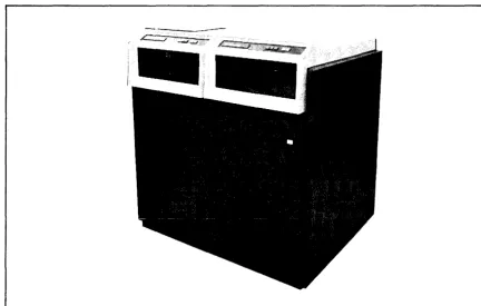
1 MSU0500/0501 Mass Storage Unit. . . . 1INTRODUCTION
The MSU0500 and MSU050 1 Mass Storage Units are dual-spindle, nonremovab!e disk devices with large capacity and high throughput. Salient features of each device are described below. Table 1 ~presents the characteristics in an easy-to-read format; Figure 1 depicts the MSU0500 and MSU0501. Capacities of each subsystem relative to the Mass Storage Proc-essor to which it is attached are presented in Table 2.
MSUOSOO Overview
The formatted storage capacity for the MSU0500 is 626 million 9-bit bytes (940 million characters). The peak transfer rate of the device is 1,065,000 9-bit bytes per second (1,597,000 characters per second). The MSU0500 has one access path per spindle and a dual access feature option (MSFOO 11) is available to provide an additional non-simultaneous access path, providing a path to each device adapter. This option is required when configuring dual channel subsystems.
The MSU0500 units connect to and are controlled by the MSP0602/0603/0605 Mass Storage Processors. They can also be connected to the MSP8000/800 1 and MSP0604/0607/ 0608/0609 Mass Storage Processors. A description of the Mass Storage Processors and diagrams of MSU0500 attachment can be referenced later in this manual. The MSUOSOO can be intermixed with the MSU0400/0402/045 1 as shown in the diagrams.
[image:4.615.90.523.409.684.2]MSUOSOI Overview
The formatted storage capacity for the MSU050 1 is 1101 million 9-bit bytes (1651.5 million characters). The peak transfer rate of the device is 1,065,000 9-bit bytes per second (1,597,000 characters per second). Effective transfer rate is 983,040 9-bit bytes per second (1,474,560 characters per second). The MSU050 1 responds to a request device type com-mand with its own unique identification number. Therefore, it can be mixed with 64-word sector devices, i.e., MSU0451 and MSU0500. The MSU050 1 has one access path per spindle, and a dual access feature option (MSFOO 11) is available to provide an additional non-simultaneous access path, providing a path to each device adapter. This option is required when configuring dual channel subsystems. Refer to the Mass Storage Processor description and diagrams later in this manual.
The MSU050 1 units can connect to and are controlled by the MSP8000/800 1, MSP0604/ 0607/0608/0609 Mass Storage Processors, described later in this manual. The MSU050 1 units can also connect to MSP0602/0603 or 0605 Mass Storage Processors with the appro-priate MSU050 1 Attachment Feature, MSF 1 046 (for MSP0605 attachment) or MSF 1 045 (for MSP0602/3 attachment).
TABLE I. MASS STORAGE UNIT CHARACTERISTICS
Characteristic
FORMATTED CAPACITY: a (Per Dual-Spindle Unit)
Characters 9-bit bytes TRANSFER RATE:
Characters per second 9-bit bytes pt:r second ACCESS TIMES (milliseconds):
Minimum Seek Time Average Seek Time Maximum Seek Time Average Latency
DISK MODULES (two non-operator removable modules per MSU0500/0501):
Number of spindles Number of disks Recording Surfaces Tracks/recording surface Rota tional speed (RPM) SIMULTANEITY: PHYSICAL CHARACTERISTICS: Height Widih Depth Weight ELECTRICAL: Power Power Consumption Heat Dissipalion Frequency ENVIRONMENT:
Temperature (operating) Relative Humidity
aFor subsystem capacities, refer to Table 2.
MSUOSOO MSUOSOI
940 million 626 million
1,651 million 1,101 million
Peak Effective
1,597,000 921,600 1,065,000 614,400
Peak Effecdve
1,597,000 1,474,560 1,065,000 983,040
... 1 - - - 10 ... 1 - - - 25
... f - - - -50
..
..
... f - - - -8.3 ---~.
... i - - - -Included ---!.~
[image:5.613.93.525.236.704.2]... f - - - 2 - - - -...
... 1---12---~·
19 1630
20 1680 ... 1---3600---~.~
2
DUJ:ing data transfer on one spindle, a simultaneous seek operation can be performed on all other spindles attached to the same control.
44.4 in. (112.7 cm) 42 iIi. (l06.6 em) 33.3 in. (84.5 cm) 1080 lb (489.8 kg)
208 Vac + 10%, -15%,3 phase 2.7 kVA
7300 Btu/hr 60 Hz ± Yz Hz
59°F to 90°F (15°C to 32°C) 10% to 80%
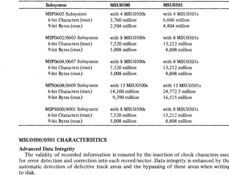
TABLE 2. SUBSYSTEM CAPACITIES
Subsystem
MSP0605 Subsystem 6-bit Characters (max) 9-bit Bytes (max)
MSP0602/0603 Subsystem 6-bit Characters (max) 9-bit Bytes (max)
MSP0604/0607 Subsystem 6-bit Characters (max) 9-bit Bytes (max)
MPS0608/0609 Subsystem 6-bit Characters (max) 9-bit Bytes (max)
MSP8000/8001 Subsystem 6-bit Characters (max) 9-bit Bytes (max)
MSU0500/0501 CHARACTERISTICS Advanced Data Integrity
MSU0500
with 4 MSU0500s 3,760 million 2,504 milli on
with 8 MSU0500s 7,520 million 5,008 million
with 8 MSU0500s 7,520 million 5,008 million
with 15 MSU0500s 14,100 million
9,390 million
with 8 MSU0500s 7,520 million 5,008 million
MSU0501
with 4 MSU0501s 6,606 million 4,404 million
with 8 MSU0501s 13,212 million
8,808 million
with 8 MSU0501s 13,212 million
8,808 million
with 15 MSU0501s 24,772.5 million 16,515 million
with 8 MSU0501s 13,212 million
8,808 million
The validity of recorded infonnation is ensured by the insertion of check characters used for error detection and correction into each record/sector. Data integrity is enhanced by the automatic detection of defective track areas and the bypassing of these areas when writing to disk.
A write protect capability - standard with this unit - allows the user to protect the two individual disk modules against inadvertent writing.
Efficient I/O Channel Utilization
More efficient utilization of the I/O channel is achieved through the use of a rotational position sensing feature, which is included with the MSU0500j050 1. This feature can be used to reduce the effective latency time of the device. The average seek time is 25 milli-seconds.
System Reliability/Availability
Increased reliability has been achieved by the integration of the read/write heads, actuator arms and disks into a sealed disk module. This improved design increases the reliability and environmental control, minimizing the possibility of disk surface contamination.
Enhanced diagnostic ability reduces both systenl time required for online repair and the total offline repair time spent on the device itself. Online error and status reporting to the central processor system allow software-controlled diagnosis of the circuitry. In addition, a hardware diagnostic ability allows offline diagnosis and testing.
Site Efficiency
[image:6.618.65.532.62.419.2]Options
Refer to Table 3 for a list of available options. Refer also to the information in the para-graph entitled "Mass Storage Processors."
TABLE 3. MSU0500/0501 OPTIONS
Device Option Description
MSUOSOO MSFOSOO Additional Head Disk Assembly
for MSUOSOO
MSUOSOI MSKOSOI Upgrade from MSUOSOO to
MSUOSOI
MSFOSOI Additional Head Disk Assembly for MSUOSOI
MSKOS02 Upgrade from MSFOSOO to MSFOS01 Head Disk Assembly
MSFI04Sa MSUOSOI Attachment Feature on MSP0602/0603 with MSUOSOO Device Adapter (MSF 1024) installed
MSFI046a MSUOSOI Attachment Feature on MSP060S with MSlfOSOO Device Adapter (MSFI037) installed
MSFI02Sa Device Adapter for MSUOSOO/OSO 1
MSUOSOO/OSO 1 MSFI02Sa Device Adapter for MSUOSOO/OSOI on MSP0602/0603
MSFOOll Dual Access Feature
aRefer to Table 5 and to the paragraph entitled "MSP0602/0603/0605" later in this manual.
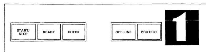
CONTROLS AND INDICATORS
Table 4 lists and describes the various controls and indicators for each MSUOSOOjOSO I unit, while Figure 2 shows the spindle control panel. The text that follows describes the operating procedures for the unit.
Device Numbering
Each spindle control panel has a recessed area (see Figure 2) for the application of spindle identification numbers.
STARTI
[image:7.620.76.529.87.434.2]STOP
BB BB
Figure 2. MSU0500/0501 Spindle Control Panel
[image:7.620.100.492.577.676.2]TABLE 4. MSU0500/0501 CONTROLS AND INDICATORS
Control
POWER ON
(Push Button/Indicator)
Description
Used to energize and remove power supplies in the unit. Located outside the front door of the right-hand spindle cabinet. Lights when power supplies are energized, and extinguishes when power is removed.
NOTE: The following controls and indicators are located on the operator's control of each spindle's cabinet (see Figure 2).
START/STOP
(Push Button/Indicator)
READY
(Indica tor)
CHECK
(push Button/Indicator)
OFF·LINE (Indicator)
PROTECT
(Push Button/Indicator)
OPERATING PROCEDURES Power-Up Sequence
Used to start or stop spindle rotation. When lighted, it indio cates that power is applied to the spindle motor. If pressed when lighted, it causes the spindle to come to a stop and the indicator light goes out.
Lights when the spindle is rotating at the proper speed, the heads are loaded, and the spindle is ready to accept com· mands.
Lights when a fault condition has occurred. In general, the indicator will be cleared by programs that analyze fault conditions. Occasionally, these programs will require the operator to correct the problem, then press the button to clear the fault registers and reset the indicator.
Lights when the spindle is in the offline mode. A spindle may be placed offline by setting the OFF·LINE switch on the maintenance panel which is accessed by opening both rear doors.
Used to inhibit or enable write operations on the disk module. When the PROTECT indicator is lighted, pressing it will turn the light off and enable write operations. When the PROTECT indicator is off,. pressing it will turn it on and inhibit write operations.
In the following procedure, it is assumed that all cables have been properly connected and secured, and that power is supplied to the unit.
Press the POWER ON button located on the front of the right-hand spindle cabinet of each unit. The POWER ON indicator will light. If the indicator fails to illuminate (indicating that power has not been applied to the unit), contact your local Honeywell field service representative.
Power-Down Sequence
1. Press the START/STOP button located on each spindle control panel. START/STOP and READY indicators will extinguish.
2. Press the POWER ON switch. The indicator will extinguish. Initialization
Startup Sequence
In the following procedure, it is assumed that the Power-Up and Initialization procedures have been successfully completed.
1. Select appropriate permit/protect mode for each spindle via the PROTECT button. 2. Press START/STOP button on each spindle control panel. START/STOP indicators
wiIllight and after a few seconds the READY indicators will light. 3. The MSU0500/050 1 is ready to accept commands when READY lights. OPERATO R l\1AINTEN AN CE
The only operator maintenance required is that of general cleaning. GeneralOeaning
Operators should keep cabinets clear and free of dust.
MASS STORAGE PROCESSORS
The mass storage processors for the MSU0500 and MSU050 I are microprogranlmed peripheral processors that connect to the central processor via high-speed I/O channels and relieve the central processor of all device-oriented functions.
Components
Each mass storage processor consists of the following components (also see Figure 3): o Read-Only Memory - provides access and storage to resident control and diagnostic
microprograms.
o Microprocessor - interprets all the microinstructions and performs their specified operations.
o Scratch-Pad Memory - provides temporary storage for data buffering parameters and command storage.
o Peripheral Subsystem Interface Control - provides the logic and buffering necessary to interface with the one-byte-wide PSI to sustain data transfer and control dialogs. o Device Level Interface Control - provides the logic and buffering necessary to
inter-face with DLIs to sustain data transfer and control dialogs in addition to verification information generation and checking.
10M
---,
PSI CONTROLREAD-ONLY MEMORY
MICROPROCESSOR
SCRATCH-PAD MEMORY
I
I
DLIC~NTRDL
i
I
1 ,
Figure 3. Mass Storage Processor Components
[image:9.620.181.417.455.698.2]Options
Refer to Table 5 for a list of Mass Storage Processor options. These options will be refer-enced in the individual processor discussions that follow.
TABLE 5. MASS STORAGE PROCESSOR OPTIONS
Mass Storage Processor
MSP0602/0603 MSP0602/0603/0605 MSP0605 MSP0604/0607 Option MSF1024 MSF1025 MSF1033 MSF1035 MSF1036 MSF1045 MSF1028 MSF1019 MSF1026 MSF1027 MSA1027 MSA1029 MSF1037 MSF1038 MSF1046 MSK6005 MSF1040 MSF1047 MSK6006 MSK6007 MSAI040 MSA1041
MSP0604/0607/0608/0609 MSF 1043
MSF1044
MSP0608/0609 MSA1042
MSA1043
Description
Device Adapter for MSU0500
Device Adapter for MSU0501/0500
When no MSU500s are present on a MSP0602/0603, the MSF 1025 Device Adapter must be ordered to configure MSU0501s, or MSU0500s and MSU0501s in combination. If only MSU0500 is configured, order MSF 1024.
Drive Expansion for more than 16 MSU0400/0402/0451 single channel units
Device Adapter for MSU0400/0402/0451
Dual Processor Crossbar (one per two processors)
MSU0501 Attachment Feature on MSP0602j0603 with MSU0500 Device Adapter MSF 1 024 installed
Dual Simultaneous Channel used when no MSU0500j0501s are configured
Nonsimultaneous IOMjDATANET channel for use when no MSU0500/0501s are configured
Nonsimultaneous 10M Channel used when MSU0500j0501s are configured
Nonsimultaneous DATANETChannel used when MSU0500/ 0501s are configured
Addressing Capability for four (4) MSU0400/0402/0451 units
Addressing Capability for two (2) MSU0500/0501 units
Device Adapter for MSU0500
Device Adapter for MSU0400/0402/04S 1
MSUOS01 Attachment Feature on MSP060S with Device Adapter MSF1037 installed
Upgrade Kit (from MSP060S to MSP0602)
Device Adapter for MSU0400/0402/04S 1 on MSP0607 only
Device Adapter for MSU0400j0402/04S 1 on MSP0604 only
Upgrade Kit, MSP0604 to an MSP0608
Upgrade Kit, MSP0607 to an MSP0609
Addressing Capability for four MSU0400/0402/04S 1 s for MSP0604/0607 only
Addressing Capability for two MSUOSOO/OSOls for MSP0604/0607 only
Nonsimultaneous (switched) DAT ANET Channel for MSP0604/0607/0608/0609
Nonsimultaneous (switched) 10M Channel for MSP0604/ 0607/0608/0609
Addressing Capability for MSU0400/0402j04S 1 (one per four MSUs)
[image:10.621.105.541.109.743.2]TABLE 5 (CONT). MASS STORAGE PROCESSOR OPTIONS
Mass Storage Processor Option Description
MSP8000
MSP8001
MSF1041
MSF1042
MSF1048
MSF8000
MSA8000 MSA8001 MSK8000
MSF8001
Device Adapter for Attachment of up to 16 MSU0400j 0402j0451s for the MSP0609 only
Drive Expansion for up to 7 additional MSU0500j0501 s for the MSP0608j0609
Device Adapter for attachment of MSU0400j0402j0451s for the MSP0608 only
Device Adapter for MSU0400j0402j0451, limit of 16 drives
Addressing Capability for four MSU0400j0402j0451s Addressing Capability for two MSU0500j0501s
Upgrade Kit, MSP8000 to MSP8001 (must replace MSF and MSAs with MSP8001 features)
Device Adapter for attachment of up to 16 MSU0400j 0402j0451s
MSP8000j8001
MSA8002 MSA8003 MSF8002 MSF8003
Addressing Capability for four MSU0400j0402j0451 s Addressing Capability for two MSU0500j0501s Nonsimultaneous DATANET Channel
Nonsimultaneous 10M Channel
MSP0602j0603j060S
The MSP0602 and MSP0605 are integrated processors located in the integrated control unit (leU); the MSP0603 is a freestanding processor.
The MSP0602j0603j0605 can be configured with single channels and nonsimultaneous switched channels. Any two of the processors can be crossbarred to provide dual simulta-neous access to any two disk units. A dual simultasimulta-neous channel on one processor is not possible due to the high transfer rate of the MSU0500j050 1.·
In multiple system configurations the mass storage subsystem can be expanded to two processors to provide four channel connectability plus four nonsimultaneous channels. Any system will have access to any of the disk units within the subsystem.
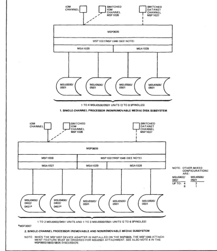
MSU0500j0501 Attachment
The MSP0602j0603 supports one of the following MSUOSOOjOSOl configurations (see Figures 4 and 5).
o Up to 8 MSU0500j050 I units (16 spindles)
o Up to 8 MSU0500j050 1 units (16 spindles) and up to 16 MSU0400j0402j0451 units The MSP0605 supports one of the following configurations (see Figure 6).
o Up to 4 MSU0500/0501 units (8 spindles)
o Up to 3 MSU0500j0501 units (6 spindles) and up to 2 MSU0400j0402j0451 units o Up to 2 MSU0500j050 1 units (4 spindles) and up to 4 MSU0400j0402j0451 units o Up to 1 IvISUOSOOj050 1 unit (2 spindles) and up to 6 lVISU0400j0402!0451 units
NOTES:
1. When no MSU0500s are present on the MSU0602j0603 (Feature MSFI024 Device Adapter is not installed), the MSFI025 Device Adapter must be ordered when configuring the MSU050 1.
2. When the MSFI024 Device Adapter is installed on the MSP0602j0603 (i.e., MSU0500 installed), the MSF 1045 Attachment Feature is required for MSUOSO 1 attachment.
[image:11.615.79.512.50.323.2]MSA 1 029
3. When the MSF 1037 Device Adapter is installed on the MSP0605, the MSF 1046 Attachment Feature must be ordered for MSUOSO 1 attachment.
4. When no MSUOSOO units are present on the MSP060S, the MSFI037 Device Adapter and the MSFI046 Attachment Feature must be ordered for MSUOSOI attachment.
S. The MSUOSOO may be upgraded to the MSUOSOI via the MSKOSOI Upgrade Option. Also~ the MSKOS02 upgrades the MSFOSOO Additional Head Disk Assembly to the MSFOSOI Additional Head Disk Assembly.
10M CHANNEL
" "
O
SWITCHED 10M CHANNEL / , , " MSF1026MSP0602/MSP0603
O
SWITCHED DATANET CHANNEL I MSF1027I
I
MSF1024/MSF1045 (SEE NOTE BOTTOM OF PAGEl
MSA1029 MSA1029
1 to 8 MSU0500/0501 UNITS (2·16 SPINDLESI
1. SINGLE·CHANNEL PROCESSOR (NONREMOVABLE MEDIAl DISK SUBSYSTEM
10M
0
SWITCHED CHANNEL 10MCHANNEL , , " MSF1026
,,"
"
MSP0602/0603
.
nSWITCHED DATANET Y CHANNEL MSF1027
I
I
MSA1027
1 to 8 MSU0500/0501 UNITS (2 TO 16 SPINDLESI AND 1 TO 16 MSU0402/0451 UNITS "MSFOOO7 ROTATIONAL POSITION SENSING
2. SINGLE·CHANNEL PROCESSOR (REMOVABLE AND NONREMOVABLE MEDIAl DISK SUBSYSTEM
NOTE: WHEN THE MSF1024 DEVICE ADAPTER IS INSTALLED ON THE MSP0602/0603. THE MSF1045 ATTACHMENT FEATURE MUST BE ORDERED FOR MSU0501 ATTACHMENT. SEE ALSO NOTE 1 IN rHE MSP0602/0s03/0605 DISCUSSION.
[image:12.617.117.542.167.595.2]10M CHANNEL
O
SWITCHED QSWITCHED 10M DATANET CHANNEL CHANNE L / / / " MSF1026 I MSF1027/ I
MSP0602/0603
MSF1024/MSF1045 ISEE NOTE'
1 TO 4 MSU0500/0501 UNITS 12 TO 8 SPINDLES} aMSF0011 DUAL ACC~SS FEATURE
10M CHANNEL
O
SWITCHEDQ
SWITCHED 10M DATANET CHANNEL CHANNEL / / / / " MSF1026 : MSF1027MSP0602/0603
MSF1024/MSF1045 ISEE NOTEI
1. DUAL-CHANNEL, DUAL PROCESSOR CROSSBAR RED INONREMOVABLE MEDIAl DISK SUBSYSTEM NOTE WHEN THE MSF1024 DEVICE ADAPTER IS INSTALLED ON THE MSP0602/0603, THE MSF1045 ATTACHMENT
FEATURE MUST BE ORDERED FOR MSU0501 ATTACHMENT. SEE ALSO NOTE 1 IN THE MSP0602/0603/0605 DISCUSSION_
SWITCHEDO DATANET CHANNEL MSF 1027 I
I "
/
O
SWITCHED 10M CHANNEL / / / MSF1026SWITCHEDQ DATA NET CHANNEL MSF1027 I
I
"
O
SWITCHED 10M CHANNEL / / / / MSF1026MSP0602/0603 MSP0602i0603
'---~+---~
aMSFOOll. DUAL ACCESS FEATURE bMSF0006, DUAL-ACCESS FEATURE CMSFOOO7, ROTATIONAL POSITION SENSING
1 TO 8 MSU0500/0501 12 TO 16 SPINDLES} AND 1 TO 6 MSU0402/0451 UNITS
2_ DUAL-CHANNEL, DUAL PROCESSOR CROSSBARRED IREMOVABLE AND NONREMOVABLE MEDIAl DISK SUBSYSTEM NOTE WHEN THE M:iF1024 DEVICE ADAPTER IS INSTALLED ON THE MSP0602/0603, THE M~;F1045 ATTACHMENT
FEATURE MUST BE ORDERED FOR MSU0501 ATTACHMENT. SEE ALSO NOTE 1 IN THE MSP0602/0603/0605 DISCUSSION_
Figure 5. MSP0602/0603 Dual-Channel Configurations
1('1
[image:13.620.79.509.28.523.2]10M CHANNEL
. /
MSF1038 "
. /
10M CHANNEL
. /
MSA1029 . / "
O
SWITCHED10M CHANNEL , , " MSF1026
MSP0605
~"SF1037/MSFi046 (SEE NOiE,
Q
SWITCHEDDATANET CHANNEL MSF1027 I I
MSA1029
1 TO 4 MSU050010501 UNITS (2 TO 8 SPINDLES)
1. SINGLE·CHANNEL PROCESSOR (NONREMOVABLE MEDIAl DISK SUBSYSTEM
O
SWITCHED10M CHANNEL , , " MSF1026
MSP0605
Q
SWITCHEDDATANET CHANNEL MSF1027 I I
MSF1037/MSF1046 (SEE NOTE)
~
____ . -___ M_S_A_10_27 ____~
____~
___M_SA~1_0_29
____ L-____~
___ M_S_A_1_02_9 __~
_____=J
1 TO 2 MSU0402/0451 UNITS AND 1 TO 3 MSU0500/0501 UNITS (2 TO 6 SPINDLES) aMSF0007
2. SINGLE·CHANNEL PROCESSOR (REMOVABLE AND NON REMOVABLE MEDIAl SUBSYSTEM NOTE: WHEN THE MSF1037 DEVICE ADAPTER IS INSTALLED ON THE MSP0605, THE MSF1046 ATTACH·
MENT FEATURE MUST BE ORDERED FOR MSU0501 ATTACHMENT. SEE ALSO NOTE 4 IN THE MSP0602/0603/0605 DISCUSSION.
Figure 6. MSP0605 Configurations
MSP0604/0607/0608/0609 ;
NOTE: OTHER MIXED CONFIGURATION:> ARE:
MSU0402/ MSU0500/
0451 0501
UPTO: 4 2
-6 1
The following mass storage processors are available for the DPS 8, Level 66/DPS and Level 68/DPS. Following the list is a description of the processors and the connectability requirements for the MSU0500j050l.
o MSP0604 - Single channel (integrated) Mass Storage Processor for DPS ICU systems only
o MSP0607 - Single channel (freestanding) Mass Storage Processor for DPS systems only o MSP0608 - Dual channel (integrated) Mass Storage Processor for DPS ICU systems
only
[image:14.620.102.541.49.557.2]Upgrade Capabilities:
o MSK6006 - Upgrade, MSP0604 to MSP0608 o MSK6007 - Upgrade, MSP0607 to MSP0609
The MSP0604 is physically located within the central processing system integrated con-trol unit while the MSP0607 is a freestanding unit. Both will support up to a maximum of eight (8) MSU0500j050 1 devices or a maximum of sixteen (16) MSU0400j0402j0451 devices. Any combination of these drives will be supported up to a maximum of sixteen (16) spindles.
The MSU0500j050 1 device adapter is integrated with the controller and need not be ordered separately.
There is an upgrade kit for each of the single channel controllers, MSP0604 to MSP0608 and MSP0607 to MSP0609. When ordering these upgrade kits, the addressing features
MSAI040j41 must be replaced by MSAI042j43 where used.
One channel of the MSP0608 is integrated into the integrated control unit of the central processing system while the second channel is freestanding. The MSP0609 is totally free-standing.
Either of these controllers will support up to 15 MSU0500j050 1 devices (30 spindles) or 16 MSU0400j0402j0451 devices can also be supported.
As with the MSP0604j0607, the MSU0500j050 1 device adapter is included and can support up to eight (8) devices (16 spindles). When expanding to support up to 15 MSU0500j050 1 devices (30 spindles) or when supporting MSU0400j0402j0451 s the appro-priate device expansionjdevice adapter is required.
Refer to Table 5 for a list of the options; Figures 7 and 8 illustrate examples of MSU0500j 0501 attachment.
10M
0
SWITCHED CHANNEL 10MCHANNEL , / " MSF1044
",'"
'"
MSA1041
MSP0604/0607
.
[J
SWITCHED DATANET CHANNELI MSF1043
I
1 TO 8 MSU0501 12 TO 16 SPINDLES) AND 1 TO 16 MSU04OOI0402I0451 UNITS, TO MAXIMUM OF 16 SPINDLES TOTAL
SINGLE·CHANNEL PROCESSOR (REMOVABLE AND NONREMOVABLE MEDIA) DISK SUBSYSTEM
NOTE: MSF2047, DEVICE ADAPTER ON MSP0604, MSF1040, DEVICE ADAPTER ON MSP0607
Figure 7. MSP0604/0607 Configuration
12
MSA1042
[image:15.618.74.509.359.585.2]II
I
10M
0
SWITCHED CHANNEL 10MCHANNEL
[image:16.620.108.537.42.285.2]10M
0
SWITCHED CHANNEL DATANET CHANNEL ... MSF1044... "
" , , " , / ' MSF1043
MSP0608/0609
I
I
~
0501·b
\:Q13 \.
1 TO 8 MSUOSOO/0501 UNITS (2 TO 16 SPINDLES) AND 1 TO 16 MSU0400/0402/0451 UNITS. TO MAXIMUM OF 30 SPINDLES TOTAL aMSFOO1'. DUAL ACCESS FEATURE
bMSFOOO7, ROTATIONAL POSITION SENSING
DUAL,CHANNEL PROCESSOR (REMOVABLE AND NONREMOVABLE MEDIA) DISK SUBSYSTEM NOTE: MSF1041. DEVICE ADAPTER ON MSP0609;MSF1048. DEVICE ADAPTER ON MSP0608.
Figure 8. MSP0608j0609 Configuration
MSP8000/8001
I
J..
The MSP8000 is a single channel microprogrammable mass storage processor physically located within the DPS 8/20 or DPS 8/44 central system. The MSP800 I is a dual channel microprogrammable mass storage processor. One channel of the MSP8001 is integrated into the DPS 8/20 or DPS 8/44 while the second channel is freestanding.
Both the MSP8000 and MSP8001 will support up to a maximum of eight (8) MSU0500/ 0501 devices. The processors also support a maximum of sixteen (16) MSU0400/0402/045I. The MSU0500/050 1 device adapter is included as an integral feature of the MSP8000/ 8001. There is also an upgrade kit to upgrade the MSP8000 to MSP800I.
Refer to Table 5 for a list of MSP8000j8001 options, and to Figures 9 and 10 for examples of MSU0500/0501 attachment to the MSP8000 and MSP800I, respectively. Controls and Indicators
The operator control panel, located on the top of the Mass Storage Processor for free-standing units or in the Integrated Control Unit for integrated versions,} contains the con-trols and indicators required for normal operation of the MSP. Refer to Figures 11 and 12, respectively. A description of each pushbutton/indicator is given in Table 6.
1 Refer to the introductory paragraph under the heading "Mass Storage Processors" earlier in the manual for a defmition
10M CHANNEL
" "
O
SWITCHED10M CHANNEL ,,'" " MSF8003
MSP8000
MSU0500/0501 DEVICE ADAPTER INCLUDED
Q
SWITCHEDDATANET CHANNEL MSF8002 I
I
'---~~---1 TO 8 MSU0500/0501 UNITS (2 TO 16 SPINDLES) 1. SINGLE·CHANNEL PROCESSOR (NONREMOVABLE MEDIA) DISK SUBSYSTEM
10M CHANNEL
"
"
"O
SWITCHED10M CHANNEL , , " MSF8003
MSP8000
MSU0500/0501 DEVICE ADAPTER INCLUDED
MSA8001 MSA8001 MSA8000
Q
SWITCHEDDATANET CHANNEL MSF8002 I
I
MSF8000
MSA8000
1 TO 16 MSU0451 AND/OR 1 TO 8 MSU0500/0501 UNITS (NOT TO EXCEED 16 SPINDLES) aMSF0007 ROT A TlONAL POSITION SENSI NG
2. SINGLE·CHANNEL PROCESSOR IREMOVABLE AND NONREMOVABLE MEDIA) DISK SUBSYSTEM
Figure 9. MSP8000 Configurations
14
CONFIGURATIONS ARE:
MSU04XX MSU050X
UP TO 0 UP TO 8
4 6
8 4
12 2
[image:17.613.80.514.36.535.2]10M CHANNEL
/ /
O
SWITCHED 10M 10M CHANNEL CHANNEL ,,/' '" MSF8003MSP8001
O
SWITCHEO DATANET CHANNEL / / / / ' " MSF80021 TO 8 MSU0500/0501 OR 1 TO 16 MSU0400/0402/0451 UNITS (16 SPINDLES MAXIMUM) aMSFOOll. DUAL ACCESS FEATURE
bMSFOOO6. DUAL ACCESS FEATURE cMSFOOO7. ROTATIONAL POSITION SENSING
1. DUAl·CHANNEl PROCESSOR (REMOVABLE AND NONREMOVABlE MEDIA) DISK SUBSYSTEM
10M
CHANNEL
O
SWITCHED 10M 10M CHANNEL
CHANNEL
O
SWITCHED DATANET CHANNEL / " , / MSF8003 ",,,,'" MSF8002
/ / '"
'"
MSP8001
1 TO 8 MSU050010501 UNITS 12·16 SPINDLES) aDUAL ACCESS FEATUFIE
2. DUAl·CHANNEL (NONREMOVABLE MEDIA) DISK SUBSYSTEM
Figure 10. MSP8001 Configurations
NORMAL READY OVER TEMP
CONFIGURATION: MSU04XX MSUOSOX UPTO 0 UPTO 8
4 6
8 4
12 2 16 0
t.==~=~=E=A=K=E=R::::J
[DE]
~
OFF TEST TROUBLE ALARMRESET
-A
II
START
IIIAUTOMATICII'N;V,....NI,~IEXT 111~~;~RA;'~n~'II'
HALTED
',I,IIN!T!AL!ZE
,II
Il
MANUA L 'I,-=:' =5=TO::::R E=:::JI ,,!IV l e nU~
I 11l.=/I======:::..1'1 t..=1
======:::J
-Figure 11. Freestanding Mass Storage Processor Control Panel
t--- ~
[image:18.623.111.543.45.461.2]r---\1
STARTIII
LA=U=T=O=M=A=TI=C:.J 1 ..=IN=~=o=IN=~=XT:::::.J
... MANUAL .... STORE ~ I - - ~
""---A B C 0
-
-OPERATOR II HALTED II INITIALIZE INTERRUPT
Figure 12. Integrated Mass Storage Processor Control Panel
TABLE 6. MASS STORAGE PROCESSOR CONTROLS AND INDICATORS
Push Button/Indicator Function
START
AUTOMATIC/MANUAL
INT/EXT/CONT STORE
All Processors
Pressing this button when the control/processor is in the HALTED state changes it from the TROUBLE state to the READY state (see READY / TROUBLE indicator) and the indicator lights white.
This split-field indicator identifies the operational mode (green
=
AUTO-MATIC, blue=
MANUAL) of the control/processor. The button allows the operator to control the execution of the initialize and halt options of the microprogram. These options are logically enabled in the MANUAL mode. Pressing this button changes the state of the switch.This three-way split-field indicator lights red in the individual field when an error is detected. Pressing this button or executing the microprogram's error option should reset the error and turn off the indicator light. If the error persists, notify the Honeywell field engineer.
EXT - Indicates an error detected during a device adapter interface or main memory operation.
INT - Indicates an error detected internal to the processing structure of the processor (internal buses, etc.)
STORE - Indicates an error detected during the access of a microprogram from processor store.
OPERATOR INTERRUPT Pressing this button lights the indicator white and causes the execution of a special interrupt that transfers the information stored in the ADDRESS/ SIMULATE switches to the central system. The OPERATOR INTERRUPT state is reset by the microprogram and the indicator goes out.
HALTED This indicator lights blue when the control/processor goes into the halted state.
INITIALIZE Pressing this button lights the HALTED indicator and resets the control/ processor to the initialized state. The indicator lights white.
ADDRESS SIMULATE These four thumb wheel switches, used in conjunction with the maintenance panel switches permit the user to address various functions of the controIl processor, depending upon the specific application required. These switches are used mainly by the field engineer in conjunction with the maintenance panel to diagnose the control/processoro Do not change the state of these switches while they are being sensed by the microprogram.
[image:19.615.65.523.150.641.2]TABLE 6 (CONT). MASS STORAGE PROCESSOR CONTROLS AND INDICATORS
Push Button/Indicator Function
The remaining indicators/push buttons are for the freestanding processors only.
AC BREAKER ON
POWER ON
POWER OFF
NOIUv1AL TEST
READY/TROUBLE
OVER TEMP/ ALARM RESET
This indicator lights red when the cabinet circuit breaker is on and power is being applied to it from its power source panel.
NOTE: The cabinet circuit breaker is located behind the right front door at the bottom right side of the cabinet on the CKP panel. This circuit breaker applies primary service power to the cabinet and protects it from overloads.
Pressing this button when ac power is on (Ae BREAKER ON indicat,)r lit) turns the cabinet dc power on. The POWER ON indicator lights yellow and the POWER OFF indicator goes out.
Pressing this button when dc power is on turns the dc power off. The POWER OFF indicator lights green and the POWER ON indicator goes out.
This split-field indicator identifies the state (green
=
NORl\1AL, yellow=
TEST) of the MAINT PANEL MODE NORMAL/TEST switch located on the TEST area of the maintenance panel. The switch must be in the NORMAL state for online operation.NOTE: The maintenance panel is concealed behind the cover surrolinding the operator panel. If the switch is in the TEST position, the operator may open the cover and reset the switch to NORMAL.
This split-field indicator identifies the operational state (green
=
READY, red=
TROUBLE) of the control/processor.NOTE: The trouble state exists when the HALTED indicator is on or when· the OPERATIONAL MODE OFFLINE/ONLINE switch located on the TEST area of the maintenance panel is set to OFFLINE. If the HALTED indicator is on, the operator may attempt to set the control/processor to the READY state by using the START switch. If it does not leave the HALTED state, open the maintenance panel cover and check and reset the OFFLINE/ONLINE switch to ONLINE if needed. If the trouble persists, the operator should notify the local Honeywell field engineer.
[image:20.620.107.544.59.650.2]UJ
Z
...J
c.:J Z
HONEYWELL INFORMATION SYSTEMS
Technical Publications Remarks Form
LEVELS 66, 68, AND DPS 8
TITLE MSUOSOO/OS01 MASS STORAGE UNIT OPERATION
o ERRORS IN PUBLICATION
...J
«
I-:J
U
SUGGESTIONS FOR IMPROVEMENT TO PUBLICATION
Your comments will be investigated by appropriate technical personnel and action wiii be taken as required. Receipt of all forms will be acknowledged; however, if you require a detailed reply, check here.
D
FROM: NAME
TITLE
COMPANY
ADDRESS
ORDER NO.,
1 . . - . ...:..A~Y...;O;...,:.,3..l-' _R_E....;",.V~ . .::..,.1 _ - - I
DATED
I
DECEMBER 1979PLEASE FOLD AND
TAPE-NOTE: U. S. Postal Service will not deliver stapled forms
I II II I
BUSINESS REPLY MAIL
FIRST CLASS PERMIT NO. 39531 WALTHAM, MA02154 POSTAGE WILL BE PAID BY ADDRESSEE
HONEYWELL INFORMATION SYSTEMS
200 SMITH STREET WALTHAM, MA 02154
ATTN: PUBLICATIONS, MS486
Honeyweii
NO POSTAGE NECESSARY IF MAILED
IN THE UNITED STATES
I .' I '. I I LU
I
.§
It?I Z
.... 3
(
I
I
I I
I
I <t:
o
...J
o
u..
I LU
I Z
I ...J
I l:) . Z
... 3
I
I<t:
o
...J
o
Honeywell
Honeywell Information Systems
In the U.S.A.: 200 Smith Street, MS 486, Waltham, Massachusetts 02154 In Canada: 2025 Sheppard Avenue East, Willowdale, Ontario M2J 1 W5
In the U.K.: Great West Road, Brentford, Middlesex TWa 9DH In Australia: 124 Walker Street, North S~ney, N.S.W. 2060