3493 All Rights Reserved © 2016 IJSETR
A Novel Based Active Type SFCL for Reducing Over
Currents and Over Voltages in a Distribution System
with Distributed Generation Units
1. P.Devendra
M.Tech Student,Dept. Of Electrical and Electronics Engineering S V U College of Engineering, S V University, Tirupati, India.
2. Dr.B.Rajani
Associate Professor, Dept. of Electrical and Electronics Engineering Siddharth institute of Engineering & Technology, Puttur, India.
3. Dr.P.Sangameswara raju
Formerly Professor in Dept. of Electrical and Electronics Engineering, S V University, Tirupati. Director of academics in Siddhartha group of institutions, Puttur, India.
Abstract:Rising public awareness for environmental
protection, increasing energy consumption, lack of power Generation, steady growth in power deregulation and utility restructuring lead to increasing usage of distributed Generationsystems (DG). DG systems installed near load centers due to tight constraints imposed on the construction
of new transmission lines for long-power transmission.Expose of distributed generation (DG) to the distribution network increases the fault current level. This will give rise to fault current which is normally greater than interrupt capability of breakers and fuses. In consideration that applying superconducting fault current limiter (SFCL) may be a good solution. In this paper, the effects of a voltage compensation type active SFCL on them are studied through theoretical derivation and simulation. The active SFCL is composed of an air-core superconducting transformer and a five level diode converter. The magnetic field in the air-core can be
controlled by adjusting the converters output current, and then the active SFCLs equivalent impedance can be regulated for current limitation and possible overvoltage suppression. During this process, in view of the changes in the locations of the DG units connected to the system, the DG unit’s injection capacities and the fault positions, the active SFCLs current-limiting and overvoltage suppressing characteristics are both simulated in MATLAB. The simulation results show that the active SFCL can play a vital role in restraining the fault current and it can contribute to avoiding damage on the relevant distribution equipment and improve the systems safety and reliability.
KEY WORDS—Distribution system,Distributed Generation (DG), Short-circuit current, voltage compensation type active Superconducting Fault Current Limiter (SFCL)
I. INTRODUCTION
In recent years, with the great development of interconnected power grid, the power network structure becomes increasingly complicated, and the system short circuit capacity and short circuit current have reached a new level which could exceed the allowable currents of the circuit breakers. To enhance the security and stability of the power system, and reduce the impact on the electrical equipment, it is
necessary to develop the technology of fault current limiters. The superconducting fault current limiters (SFCL) are regarded as the suitable solution to solve excessive fault current problems. And a great research effort was carried out in order to develop SFCL based on different concepts. Dueto increased consumption demand and high cost of natural gas and oil, Distributed Generation (DG), which generates electricity from many small energy sources, is becoming one of main components in distribution
3494 All Rights Reserved © 2016 IJSETR
systems to feed electrical loads [1]–[3]. The introduction of DG into adistribution network may bring lots of advantages, such asemergency backup and peak shaving. However, the presence ofthese sources will lead the distribution network to lose its radialnature, and the fault current level will increase. Besides, whena single-phase grounded fault happens in a distribution systemwith isolated neutral, overvoltages will be induced on the other two healthy phases, and in consideration of the installation of multiple DG units, the impacts of the induced overvoltages on the distribution network’s insulation stability and operation safety should be taken into account seriously. Aiming at the mentioned technical problems, applying superconducting fault current limiter (SFCL) may be a feasible solution. For the application of some type of SFCL into a distribution network with DG units, a few works have been carried out, and their research scopes mainly focus on current-limitation and improvement of protection coordination of protective devices [4]–[6].
Nevertheless, with regard to using a SFCL for suppressing the induced overvoltage, the study about it is relatively less. In view of that the introduction of a SFCL can impact the coefficient of grounding, which is a significant contributor to control the induced overvoltage’s amplitude; the change of the coefficient may bring positive effects on restraining overvoltage. Voltage compensation type active SFCL is already proposed [7], and analyzed the active SFCL’s control strategy and its influence on relay protection [8, 9]. In addition, a 800 V/30 A laboratory prototype was made, and its working performances were confirmed well [10]. In this paper, taking the active SFCL as an evaluation object, its effects on the fault current and overvoltage in a distribution network with multipleDG units are studied. In view of the changes in the locationsof the DG units connected into the distribution system, the DGunits’ injection capacities and the fault positions, the current limiting and overvoltage-suppressing characteristics of the active SFCL are investigated in detail.
In an effort to prevent damage to existing power-system equipment and to reduce customerdowntime, protection engineers and utility planners have developed elaborate schemes to detectfault currents and activate isolation devices (circuit breakers) that interrupt the over-currentsufficiently rapidly to avoid damage to parts of the power grid. While these traditional protectionmethods are effective, the ever-increasing levels of fault current will soon exceed the interruptioncapabilities of existing devices.
Analysis of DG Impact on power system: When DGs are integrated into a distribution system, the Thévenin impedance seen from a possible fault
location will decrease and thus the corresponding fault current level will increase, which may exceed the interrupting capacity of the installed CBs. For example, when a fault F1 occurs in Figure 1, the fault
current flowing through CB2 (2CBI) is calculated as:
ICB2IsIDG (3)
Where, sI I I is the fault current flowing through CB2
from the source feeder before the presence of DG, then the resulting 2CBwill be greater than sI with help of DGI supplied by DG. Therefore, in some cases the fault current 2CBin the system with DG may exceed the rated current of the specific CB, which is selected in accordance with I. additionally, the application of DG in a distribution network may cause wrong relay coordination. For in-stance, the OCRs R1, R2 and R3
in Figure 1 have been coordinated properly for a fault at F1 and F2.The operating time of R2 is larger
than that of R3 by a certain CTI value while the
operating sequence for relay R1 and R2 is similar.
However, when DG is connected, the coordination between these two pairs of relays (R1-R2 and R2-R3)
is likely to be disturbed by the decreasing operation time of R2 and R3, which is determined by the
increasing fault current flowing through them. Therefore, the CTI be-tween R2 and R3 may decrease
and CTI between R1 and R2 may increase.
Figure 1. DG impact analysis.
II. THEORETICAL ANALYSIS
1. Superconducting Technologies
The concept of using the superconductors to carry electric power and to limit peak currents hasbeen around since the discovery of superconductors and the realization that they possess highlynon-linear properties. More specifically, the current limiting behavior depends on their nonlinearresponse to temperature, current and magnetic field variations. Increasing any of thesethree parameters can cause a
3495 All Rights Reserved © 2016 IJSETR
transition between the superconducting and the normal conductingregime. The curve in the lower half is a normalized plot showing the non-linearrelation between current flow in a superconductor and its resistance. The data for the curve wasmeasured while the superconductor was in a constant magnetic field and a constant temperature.Similar curves can be produced for changes in temperature and magnetic field. The currentincrease can cause a section of superconductor to become so resistive that the heat generatedcannot be removed locally. This excess heat is transferred along the conductor, causing thetemperature of adjacent sections to increase. The combined current and temperature can causethese regions to become normal and also generate heat. The term ―quench‖ is commonly used todescribe the propagation of the normal zone through a superconductor. Once initiated, thequench process is often rapid and uncontrolled
.
The integration of renewable energy sources into electric power distribution systems can provide additional economic benefits because of a reduction in the losses associated with transmission and distribution linesIn this work a SFCL model is designed. SFCL is an innovative fault current limiter. It works on the principle of Superconducting Property. It is inactive e under normal condition. It is in active under fault condition; it inserts some resistance into the line to limit the fault current. It suppresses the fault current within first half cycle only. It operates better than Circuit breakers, Relays, because the Circuit breakers take minimum 2-3 cycles before they getting activated. The effect of SFCL on micro grid fault current observed. The optimal place to SFCL is determined [10]. We have proposed voltage compensation type active SFCL in previous work [7], and analyzed the active SFCL’s control strategy and its influence on relay protection
2. Proposed model and operating Principle
of the Active type SFCL
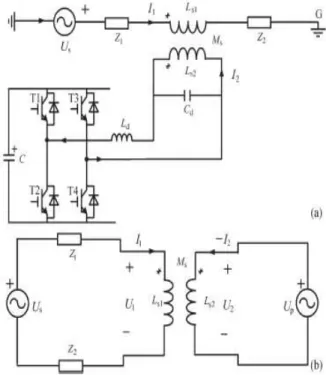
As shown in Fig. 1(a), it denotes the circuit structure of the single-phase voltage compensation type active SFCL, which is composed of an air-core superconducting transformer and Five level diode converter. Ls1, Ls2 are the self-inductance of two superconducting windings, and Ms is the mutual inductance. Z1 is the circuit impedance and Z2 is the load impedance. Ld and Cd are used for filtering high order harmonics caused by the converter. Since the voltage-type converter’s capability of controlling power exchange is implemented by regulating the
voltage of AC side, the converter can be thought as a controlled voltage source Up. By neglecting the
losses of the transformer, the active SFCL’s equivalent circuit is shown in Fig. 2(b).
Fig. 2. Single-phase voltage compensation type active SFCL. (a) Circuit structure and (b) equivalent circuit.
In normal (no fault) state, the injected current (I2) in thesecondary winding of the transformer will
be controlled to keepa certain value, where the magnetic field in the air-core can becompensated to zero, so the active SFCL will have no influenceon the main circuit. When the fault is detected, the injectedcurrent will be timely adjusted in amplitude or phase angle, soas to control the superconducting transformer’s primary voltagewhich is in series with the main circuit, and further the faultcurrent can be suppressed to some extent.
Below, the suggested SFCL’s specific regulating mode isexplained. In normal state, the two equations can be achieved.
1 1 2 1 1 2 1 2 2(
)
1
.
2
S S S P S SU
I Z
Z
j L I
j M I
U
j M I
j L I
Controlling I2 to make jωLs1 I1− jωMs I2= 0 and the
primary voltage U1 will be regulated to zero.
Thereby, the equivalent limiting impedance ZSFCL is zero (ZSFCL = U1/I1), and I2can be set as ˙
3496 All Rights Reserved © 2016 IJSETR
I2=Us_Ls1/Ls2/(Z1+ Z2)k, where k is the coupling
coefficient and it can be shown as k = Ms/ √Ls1Ls2.Under fault condition (Z2 is shorted), the main current will rise from I1 to I1f , and the primary voltage will increase to U1f .
1 1 1 2 1 2 1 1 14
f S f S S S S SU
j L I
j M I
U
j L
I Z
j M
Z
j L
The current-limiting impedance ZSFCLcan becontrolled in:
1 2 1 1 1 15
f S S SFCL S f S S aU
j M I Z
j L
Z
j L
I
U
j M I
According to the difference in the regulating objectives of I2, there are three operation modes:
1) Making I2 remain the original state, and the
limiting impedance
ZSFCL−1 = Z2 (jωLs1)/(Z1 + Z2 + jωLs1).
2) Controlling I2 to zero, and ZSFCL−2 = jωLs1.
3) Regulating the phase angle of I2 to make
the angle
Difference between ˙Us and jωMs I˙2 be 180◦ By settingjωMs I2 = −c Us,
AndZSFCL−3 = cZ1/(1 − c) +jωLs1/(1− c).
The air-core superconducting transformer has many merits, such as absence of iron losses and magnetic saturation, and it has more possibility of reduction in size, weight and harmonic than the conventional iron-core superconducting transformer [11], [12]. Compared to the iron-core, the air-core can be more suitable for functioning as a shunt reactor because of the large magnetizing current [13], and it can also be applied in an inductive pulsed power supply to
decrease energy loss for larger pulsed current and higher energy transfer efficiency [14], [15].
Fig.3. Application of the active SFCL in a distribution system with DG units
There is no existence of transformer saturation in the air-core, and using it can ensure the linearity of ZSFCL
well.
.
3. Placement of SFCL in distribution system
with distributed generation (DG) units
As shown in Fig. 3, it indicates the application of the active SFCL in a distribution network with multiple DG units, and the buses B-E are the DG units’ probable installation locations. When a single-phase grounded fault occurs in the feeder line 1 (phase A, k1 point), the SFCL’s mode 1 can be automatically triggered, and the fault current’s rising rate can be timely controlled. Along with the mode switching, its amplitude can be limited further. In consideration of the SFCL’s effects on the induced overvoltage, the qualitative analysis is presented.
In order to calculate the overvoltage’s induced in the othertwo phases (phase B and phase C), the symmetrical componentmethod and complex sequence networks can be used,and the coefficient of grounding G under this condition canbe expressed as G = −1.5m/(2 + m) ± j√3/2, where m =X0/X1, and X0
is the distribution network’s zero-sequencereactance, X1 is the positive-sequence reactance . Further,the
amplitudes of the B-phase and C-phase over voltages can be
21
3
6
2
BO CO ANG
G
U
U
U
G
Where UAN is the phase-to-ground voltage’s root
3497 All Rights Reserved © 2016 IJSETR
As shown in Fig. 4, it signifies the relationship betweenthe reactance ratio m and the B-phase
overvoltage. It shouldbe pointed out that, for the distribution system with isolatedneutral-point, the reactance ratio m is usually larger than four.Compared with the condition without SFCL, the introductionof the active SFCL will increase the power distributionnetwork’s positive-sequence reactance under fault state. SinceX0/(X1 + ZSFCL) <
X0/X1, installing the active SFCL canhelp to reduce
the ratio m. And then, from the point of the viewof applying this suggested device, it can lower the overvoltage’samplitude and improve the system’s safety and reliability.Furthermore, taking into account the changes in the locationsof the DG units connected into the distribution system, the DGunits’ injection capacities and the fault positions, the specificeffects of the SFCL on the fault current and overvoltage may bedifferent, and they are all imitated in the simulation analysis.
Fig. 4. Relationship between the reactance ratio m and the B-phase overvoltage
.
As shown in Fig. 4, it signifies the relationship between the reactance ratio m and the B-phase overvoltage. It should be pointed out that, for the distribution system with isolated neutral-point, the reactance ratio m is usually larger than four. Compared with the condition without SFCL, the introduction of the active SFCL will increase the power distribution network’s positive-sequence reactance under fault state. Since X0/(X1 + ZSFCL) <
X0/X1, installing the active SFCL can help to reduce
the ratio m. And then, from the point of the view of applying this suggested device, it can lower the overvoltage’s amplitude and improve the system’s safety and reliability. Furthermore, taking into account the changes in the locations of the DG units connected into the distribution system, the DG units’ injection capacities and the fault positions, the specific effects of the SFCL on the fault current and overvoltage may be different, and they are all imitated in the simulation analysis.
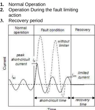
4. Operating sequence of SFCL
1. Normal Operation
2. Operation During the fault limiting
action
3. Recovery period
Figure 5.sfcl operating sequence
III. SIMULATION STUDY
1. Simulation Circuit Analysis
Fig 6: Simulation Circuit of SFCL with DG units
For purpose of quantitatively evaluating the current-limiting and overvoltage-suppressing characteristics of the active SFCL, the distribution system with DG units and the SFCL, as shown in Fig. 3 is created in MATLAB. The SFCL is installed in the behind of the power supply Us, and two DG units are included in
the system, and one of them is fixedly installed in the Bus B (named as DG1). For the other DG, it can be installed in an arbitrary position among the Buses C– E (named as DG2). The model’s main parameters are
3498 All Rights Reserved © 2016 IJSETR
shown in Table I. To reduce the converter’s design capacity making the SFCL switch to the mode 2 after the fault is detected, and the detection method is based on measuring the main current’s different components by Fast Fourier Transform (FFT) and harmonic analysis.
Mainly SFCL has air core transformer and PWM converter, in the proposed method we got the output voltage of three phase bridge inverter having only two pulse output voltages. Because of this we are getting some distortions in the output current. So in order to eliminate these ripples in the proposed inverter we go for extension method. In this method we use a Diode Clamped Multilevel inverter in SFCL to reduce those ripples in the current and to increase the pulses in the voltage level. By this the system performance is improved and the efficiency also improved.
2.Overvoltage-Suppressing Characteristics
of the SFCL
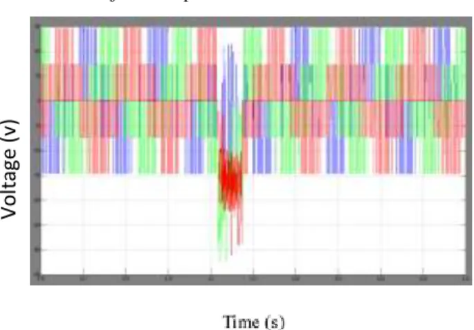
Supposing that the injection capacity of each DG is about 80% of the load capacity (load 1), and the fault location is k1 point (phase-A is shorted), and the fault time is t = 0.2 s, the simulation is done when the DG2 is respectively installed in the Buses C, D, and E, and the three cases are named as case I, II, and III. Fig. 6 shows the SFCL’s overvoltage- suppressing characteristics and the waveforms with and without the SFCL are both listed. For the cases I, II, and III, the overvoltage’s peak amplitude without SFCL will be respectively 1.14, 1.23, 1.29 times of normal value, and once the active SFCL is applied, the corresponding times will drop to 1.08, 1.17, and 1.2.
Table1: Parameters of system model During the study of the influence of the DG’s injection capacity on the overvoltage’s amplitude,
it is assumed that the adjustable range of each DG unit’s injection capacity is about 70% ∼100% of the load capacity (load 1), the two DG units are Located in the Buses B and E, and the other fault conditions are unchanged, Table II shows the voltage’s amplitude characteristics under this background.
Time (sec)
Time (sec)
Fig. 7. Voltage characteristics of the Bus-A under different locations of DG units. (a) Without SFCL and (b) with the active SFCL.
Along with the increase of the DG’s injection capacity, the overvoltage will be accordingly rise, and once the injection capacity is equal or greater than 90% of the load capacity, the overvoltage will exceed acceptable limit (1.3 times). Nevertheless, if the active SFCL is put into use, the limit-exceeding problem can be solved effectively. Superconducting Fault Current Limiter (SFCL) is innovative electric equipment which has the capability to reduce the fault current level within the first cycle of fault current [1]. The first-cycle suppression of fault current by a SFCL results in an increased transient stability of the power system carrying higher power with greater stability. The concept of using the superconductors to carry electric power and to limit peak currents has been around since the discovery of superconductors and the realization that they possess highly non-linear properties.
3499 All Rights Reserved © 2016 IJSETR
Table 2
DG’s injection capacities
Ratio of overvoltage to normal voltage Without SFCL With SFCL 70 % 1.25 1.19 80 % 1.29 1.12 90 % 1.33 1.22 100 % 1.38 1.29
Table 2: Overvoltage’s amplitude characteristics under different injection capacities of DG units
Fig. 8. Voltage characteristics of the Bus-A under different locations of DGunits.
3.Current-Limiting Characteristics of the SFCL By observing the voltage compensation type active SFCL’s Installation location, it can be found out that this device’s current-limiting function should mainly reflect in suppressing the line current through the distribution transformer. Thereupon, to estimate the most serious fault characteristics, the following conditions are designed: the injection capacity of each DG is about 100% of the load capacity (load 1), and he two DG units are separately installed in the Buses B and E. Moreover, the three-phase fault occurs at k1, k2, and k3 points respectively, and the fault occurring time is t = 0.2 s. Hereby, the line current characteristics are imitated. As shown in Fig. 6, it indicates the line current waveforms of the active SFCL when the three-phase shortcircuit occurs at k3 point. After installing the active SFCL,the first peak
value of the fault currents (iAf, iBf, iCf ) can be limited
to 2.51 kA, 2.69 kA, 1.88 kA, respectively, in contrast with 3.62 kA, 3.81 kA, 2.74 kA under the condition withoutSFCL. The reduction rate of the expected fault currents will be30.7%, 29.4%, 31.4%, respectively.
Fig. 8shows the SFCL’s current-limiting performances whenthe fault location is respectively k1 point t (selectingthe phase-A current for an evaluation). Along with the decreaseof the distance between the fault location and the SFCL’sinstallation position, the current-limiting ratio will increasefrom 12.7% (k1 point) to 21.3% (k2 point).Besides, as one component of fault current, natural responseis an exponential decay DC wave, and its initial value has adirect relationship with fault angle. In other words, correspondingto different initial fault angles, the short-circuit current’sPeak amplitudes will be distinguishing. Through the application ofthe active SFCL, the influence of initial fault angle on thepeak amplitude of the A-phase short-circuit current is analyzedin Fig. 8, where the fault location is k3 point. It can be seenthat, under the conditions with and without the SFCL, the shortcircuitcurrent’s peak amplitude will be smallest when the faultangle is about 130◦. At this fault angle, the power distributionsystem can immediately achieve the steady transition fromnormal state to fault state.
Time (sec) Fig.7Active SFCL’s current-limiting performances at k3 faultlocations. Time (sec) IL (A ) Vo lt ag e (v )
I
L( A )3500 All Rights Reserved © 2016 IJSETR
Time (sec)
Fig.8 Line current waveforms when the three-phase short-circuit occurs atk3 point. (a) Without SFCL (b) with SFCL
V. CONCLUSION
This paper is the quick review of Distributed Generation in India, its need, importance in near future. This paper provides how Traditional Generation is differing from Distributed Generation. In this paper, the application of the active SFCL into in a power distribution network with DG units is investigated
In this paper, the application of the active SFCL into in a power distribution network with DG units is investigated. For the power frequency overvoltage caused by a single-phase grounded fault, the active SFCL can help to reduce the overvoltage’s amplitude and avoid damaging the relevant distribution equipment. The active SFCL can as well suppress theshort-circuit current induced by a three-phase grounded fault effectively, and the power system’s safety and reliability can be improved. Moreover, along with the decrease of the distance between the fault location and the SFCL’s installation position, the current-limiting performance will increase.
In recently years, more and more dispersed energy sources, such as wind power and photovoltaic solar power, are installed into distribution systems. Therefore, the study of a coordinated control method for the renewable energy sources and the SFCL becomes very meaningful, and it will be performed in future.
REFERENCES
[1] S. Conti, ―Analysis of distribution network protection issues in presence of dispersed generation,‖ Elect. Power System‖. Res., vol. 79, no. 1, pp. 49–56, Jan. 2009.
[2] A. S. Emhemed, R. M. Tumilty, N. K. Singh, G. M. Burt, andJ. R. McDonald, ―Analysis of transient stability enhancement of LVconnected induction microgenerators by using resistive-type
fault current limiters,‖ IEEE Trans. Power Syst., vol. 25, no. 2, pp. 885–893, May 2010.
[3] S.-Y. Kim and J.-O. Kim, ―Reliability evaluation of distribution network with DG considering the reliability of protective devices affected by SFCL,‖ IEEE Trans. Appl. Supercond., vol. 21, no. 5, pp. 3561–3569,Oct. 2011.
[4] S. A. A. Shahriari, A. Yazdian, and M. R. Haghifam, ―Fault current limiter allocation and sizing in distribution system in presence of distributed generation,‖ in Proc. IEEE Power Energy Soc. Gen. Meet., Calgary, AB, Canada, Jul. 2009.
[5] S. Hemmati and J. Sadeh, ―Applying superconductive fault current limiter to minimize the impacts of distributed generation on the distribution protection systems,‖ in Proc. Int. Conf. Environ. Electr. Eng., Venice, Italy, May 2012.
[6] S.-H. Lim, J.-S. Kim, M.-H. Kim, and J.-C. Kim, ―Improvement of protection coordination of protective devices through pplication
of a SFCL in a power distribution system with a dispersed generation,‖IEEE Trans. Appl. Supercond., vol. 22, no. 3, p. 5601004,Jun. 2012.
[7] L. Chen, Y. Tang, J. Shi, and Z. Sun, ―Simulations and experimentalanalyses of the active superconducting fault current limiter,‖ Phys. C,vol. 459, no. 1/2, pp. 27–32, Aug. 2007. [8] L. Chen, Y. Tang, J. Shi, Z. Li, L. Ren, and S. Cheng, ―Control strategyfor three-phase four-wire PWM converter of integrated voltage compensationtype active SFCL,‖ Phys. C, vol. 470, no. 3, pp. 231–235,Feb. 2010.
[9] L. Chen, Y. J. Tang, J. Shi, L. Ren, M. Song, S. J. Cheng, Y. Hu, andX. S. Chen, ―Effects of a voltage compensation type active superconductingfault current limiter on distance relay protection,‖ Phys. C, vol. 470,no. 20, pp. 1662–1665, Nov. 2010.
[10] J. Wang, L. Zhou, J. Shi, and Y. Tang, ―Experimental investigation of anactive superconducting current controller,‖ IEEE Trans. Appl. Supercond.,vol. 21, no. 3, pp. 1258–1262, Jun. 2011.
[11] H. Yamaguchi and T. Kataoka, ―Stability analysis of air-core superconductingpower transformer,‖ IEEE Trans. Appl. Supercond., vol. 7, no. 2,pp. 1013–1016, Jun. 1997.
[12] H. Yamaguchi, T. Kataoka, H. Matsuoka, T. Mouri, S. Nishikata, and Y. Sato, ―Magnetic field and electromagnetic force analysis of 3-phase aircore superconducting power transformer,‖
IEEE Trans. Appl. Supercond., vol. 11, no. 1, pp. 1490–1493, Mar.
2001.
[13] M. Song, Y. Tang, N. Chen, Z. Li, and Y. Zhou, ―Theoretical analysisand experiment research of high temperature superconducting aircoretransformer,‖ in Proc. Int. Conf. Electr. Mach. Syst., Wuhan, China,pp. 4394–4397,Oct. 2008.
[14] R. Wu, Y. Wang, Z. Yan, W. Luo, and Z. Gui, ―Design and experimentalrealization of a new pulsed power supply based on the energy transferbetween two capacitors and an HTS air-core pulsed transformer,‖ IEEETrans. Plasma Sci., vol. 41, no. 4, pp. 993–998, Apr. 2013.
[15] R. Wu, Y. Wang, Z. Yan, Z. He, and L. Wang, ―Simulation and experimentalinvestigation of an inductive pulsed powersupply based on thehead-to-tail series model of an HTS air-core pulsed transformer,‖ IEEETrans. Appl. Super Cond., vol. 23, no. 4, p. 5701305, Aug. 2013.
I
L(
A
3501 All Rights Reserved © 2016 IJSETR
P.Devendrareceived B.Tech
degree Form (Electrical & Electronics Engineering) in SITAMSCollege,Chittoorin 2013.Studying M.Tech(Instrumentation and control system) in Sri Venkateswara University, Tirupathi. His areaof interest are in power system operation and control.
B.Rajani received M.E degree
in Power Systems and Automation from Andhra University, Visakhapatnam &Ph.D. from Sri Venkateswara University, Tirupathi, Andhra Pradesh Presentlyshe is working as associative professor in the SIETK College, Puttur, Andhra Pradesh.. Her areas of interest are in power systems operation &control and power quality improvement.
Dr. P.Sangameswara raju received Ph.D.
from Sri Venkateswara University, Tirupathi, Andhra Pradesh. Presently he is working as a professor & director in the Siddhartha Group of Institutions, Puttur, Andhra Pradesh. He has about 50 publications in National and International Journals and conferences to his credit. His areas of interest are in power system operation &control.