ABSTRACT
WANG, ZHUOWEI. Design and Implementation of a Distributed SnapshotFile System. (Under the direction of Vincent W. Freeh.)
The file system is an important component of an operating system. It defines the way data is stored and retrieved. Its performance and efficiency affect the overall operating system.
In this study, we design, implement, and validate a new file system built on FUSE. The file
system is a distributed file system with snapshot capability, which use MongoDB as storage backend. We introduce a patch-based new strategy to store snapshots. Further, we apply the
rsync algorithm to enhance the efficiency of classic copy-on-write snapshot as well as the network
performance. In addition, we studied the performance and the effect of some factors that affect the efficiency of the rsync enhanced copy-on-write snapshot.
Test results indicate that the file system we proposed has a performance comparable to the
popular network file system NFS. Furthermore, it shows that the rsync enhanced copy-on-write snapshot system can boost the space efficiency of the snapshot system compared to classic
© Copyright 2014 by Zhuowei Wang
Design and Implementation of a Distributed Snapshot
File System
by Zhuowei Wang
A dissertation submitted to the Graduate Faculty of North Carolina State University
in partial fulfillment of the requirements for the Degree of
Master of Science
Computer Science
Raleigh, North Carolina
2014
APPROVED BY:
Rada Y. Chirkova Emerson Murphy-Hill
DEDICATION
To my Father Xiaohua Wang, and my Mother Bei Lu To my teachers
BIOGRAPHY
The author was born in 1988 in Hangzhou, Zhejiang, China. Inspired by his parents, he became interested in science and engineering.
In 2006, he was admitted to his dream school Zhejiang University and started his major in Electronic Engineering there. Zhejiang University is also where his parents and grandparents
used to study. He made a number of friends and never felt lonely while he was there.
He came to NC State University 4 years later and finished his first master’s degree program in Operations Research in 2012. After his first Master’s degree, he started pursuing his second
ACKNOWLEDGEMENTS
I would like to thank the following people:
Dr. Vincent Freeh
Dr. Rada Chirkova
Dr. Emerson Murphy-Hill
Dr. Pual Mugge
TABLE OF CONTENTS
LIST OF TABLES . . . vii
LIST OF FIGURES . . . .viii
Chapter 1 Introduction . . . 1
1.1 Contribution . . . 2
Chapter 2 Related work . . . 3
2.1 POSIX . . . 3
2.2 FUSE . . . 3
2.3 MongoDB . . . 4
2.4 Snapshot . . . 5
2.5 Copy-on-Write . . . 5
2.6 Existing Snapshot Storage Systems . . . 5
2.7 The Rsync Algorithm . . . 6
Chapter 3 The Kabi File System . . . 7
3.1 System Modules and Layout . . . 7
3.2 File System Initialization . . . 8
3.3 Nodes and Objects . . . 9
3.3.1 Block Nodes . . . 10
3.3.2 File Node and Section Object . . . 11
3.3.3 Directory Node and Subnode Object . . . 13
3.4 File System Operations . . . 13
3.4.1 Read Operations . . . 14
3.4.2 Write Operations . . . 15
3.4.3 Consistency . . . 17
3.4.4 Deduplication . . . 18
3.5 Conclusion . . . 19
Chapter 4 Snapshot . . . 20
4.1 The Snapshot Tree . . . 21
4.2 Snapshot Nodes and Patch Object . . . 23
4.3 Snapshot Related Operations . . . 24
4.3.1 Read Operations . . . 25
4.3.2 Write Operations . . . 26
4.4 Enhancing Copy-on-Write and Deduplication . . . 29
4.4.1 Motivation . . . 30
4.4.2 The rsync algorithm . . . 31
4.4.3 Enhancing the Space Efficiency . . . 32
4.5 Conclusion . . . 33
5.1 File System Benchmark . . . 34
5.2 Efficiency of Snapshot and Deduplication . . . 35
5.2.1 Block Size and File Size . . . 37
5.2.2 Truncate Ratio . . . 37
5.3 Conclusion . . . 38
Chapter 6 Conclusion . . . 40
6.1 Future work . . . 40
LIST OF TABLES
Table 3.1 Primary Data Structures . . . 8
Table 3.2 Fields in Block Node . . . 11
Table 3.3 Fields in File Node . . . 11
Table 3.4 Fields in Section Object . . . 13
Table 3.5 Fields in Directory Node . . . 13
Table 3.6 Fields in Subnode Object . . . 14
Table 5.1 File System Performance Test . . . 35
Table 5.2 Sample Result of the Experiment . . . 37
Table 5.3 File Size to Block Size ratio . . . 38
LIST OF FIGURES
Figure 3.1 Modules of Kabi File System . . . 8
Figure 3.2 System Diagram of Kabi File System . . . 9
Figure 3.3 Basic Entities and Relations . . . 10
Figure 3.4 File Node, Section Object and Block Node . . . 12
Figure 3.5 Section Object and Block Node . . . 12
Figure 3.6 Copy-on-Write . . . 15
Figure 3.7 Write Buffer . . . 16
Figure 3.8 Consistency - Within a Snapshot . . . 18
Figure 3.9 Consistency - Across Snapshots . . . 19
Figure 4.1 Snapshots and Patches . . . 21
Figure 4.2 Snapshots in SnapFS . . . 22
Figure 4.3 An Example of Snapshot Tree . . . 22
Figure 4.4 Branches . . . 23
Figure 4.5 Root Snapshot and Non-root Snapshot . . . 24
Figure 4.6 The Principle of Patches . . . 24
Figure 4.7 Read a Snapshot . . . 25
Figure 4.8 Combine Patch Lists . . . 26
Figure 4.9 Merge Patches (Local) . . . 27
Figure 4.10 Example - Create Snapshot after Write . . . 28
Figure 4.11 Take Snapshots on Main Branch . . . 28
Figure 4.12 Take Snapshots on Side Branch . . . 29
Figure 4.13 Write a Snapshot Node . . . 29
Figure 4.14 Branching Root Snapshot Node Directly . . . 30
Figure 4.15 Classic Copy-on-Write . . . 30
Figure 4.16 Issue in Classic Copy-on-Write . . . 31
Figure 4.17 Identifying the Intention of Write Operations . . . 32
Chapter 1
Introduction
Mention “file system” and what usually comes to mind are disk file systems like FAT32 [35] or Ext4 [20], that is probably because disks are the most common persistent storage. In addition
to disk file systems, some file systems like NFS [25] can be used to access data from remote
machines. There are also some file systems designed to access non-traditional form of data and storage spaces for instance GmailFS [16, 5]. File systems can also provide useful and transparent
functionalities like encryption, compression, or soft-RAID [3, 19].
As the network bandwidth increases, we no longer have to keep our data on our local disk. Nowadays more and more data are stored online. Individuals are uploading their personal data
to web services; commercial companies are using cloud storage systems like Amazon S3 to
store their data remotely. There are a large number of reasons to store data in the cloud. It makes sharing and collaboration easier and ensures that the data can be accessed by its owner
anywhere and anytime. Though there are lots of services and applications that help us access
data online, a network file system is able to make this process totally transparent to its user and user programs. A distributed file system can also map different machines into a logically unified
volume while providing features like redundancy and load balancing. Popular distributed file
systems adopted by industry and academic institutes include NFS and AFS [12].
NoSQL databases [30] are used to store and retrieve data that is modeled differently from the
tabular relations. They provide alternatives to classic relational databases, bringing innovation
and new ideas to the community, industry and academia. Commercial companies like Google and Amazon have been using them in production environments for many years. Compared
to relational databases, they have many advantages in performance, scalability and flexibility.
However low functionality, e.g. not normalized data and poor transaction support [21], is one of their disadvantages.
consistency and query a single entity (file, directory) but little need of join queries and join
updates. A document oriented NoSQL database that focuses on performance, scalability and flexibility rather than the relational algebra may be a better fit to this task. In addition, the high
scalability of NoSQL database makes it easy to distribute the data on to different machine [29].
Furthermore, when the file system is relieved of the burden of on disk resource management by using a database as backend, developers can put more effort toward other features of the
file system such as snapshot and deduplication. A snapshot subsystem is useful. It can be used
to test installations, keep track of modifications, provide a rollback mechanism, and make the backup process more efficient.
It is becoming more and more common for a modern file system to have the capability
to take snapshots. For instance, from FAT to NTFS [33] and from Ext2 [34] to Ext4, more and more file systems have this feature built-in. The ground breaking file system ZFS [37] and
the experimental file system BTRFS [24] all come with snapshot capabilities. Deduplication is
another popular feature, where the file system tries to identify duplicated data and eliminate them in order to save storage space.
1.1
Contribution
We design a new distributed snapshot file system and study the way to improve its performance.
We use MongoDB as a backend of the file system to improve the network performance and
reliability. We introduce the rsync algorithm into the file system to identify the duplicated data between different machines and between snapshots. This improves the network performance
and snapshot efficiency. In addition, we use a new design of snapshot system which we called
it patch-based snapshot.
We validate our design by implementing it and testing it. The test results indicate that the
file system we proposed has comparable performance to the popular network file system NFS.
Furthermore, the results also show that the rsync enhanced copy-on-write snapshot system can boost the space efficiency of the snapshot system, compared to classic copy-on-write snapshot
system.
In this thesis, we propose a new design of distributed file system with snapshot capability. The design is implemented by Java, MongoDB, FUSE, and other techniques. We also propose
several new ways to improve the efficiency of the file system. We test and comparethe
Chapter 2
Related work
There is important prior work in customized file systems, NoSQL database, and snapshots. Several of them are related to this thesis and are summarized in this chapter.
2.1
POSIX
POSIX (Portable Operating System Interface), is a family of IEEE standards for operating systems [36]. It influences the design of many modern operating systems (e.g., Linux, Windows
NT and Mac). The POSIX standard defines a standard environment for operating system
(process, user, file, directory, etc.) along with a set of APIs for user programs (like fork, exec, I/O functions, etc.) [10]. Some file format standards (e.g., tar) and some shell utilities (e.g. awk,
vi) are also included in the standard. The purpose of this standard is to maintain compatibility
across different operating systems such that a user program written for one POSIX operating system will work on any POSIX operating system theoretically.
The POSIX standard specifies a set of file system APIs that define file and directory oper-ations. Any file system that implements this set of APIs should be compatible with operating
systems that follows POSIX standard.
2.2
FUSE
FUSE, the Filesystem in User Space, is a developer framework for file system development. The
framework was originally developed for AVFS [26] (a virtual file system that allows users to
look inside an archived or compressed file, or to access remote files) but has become a separate project. The framework has now been adopted into the Linux kernel and has many ports on
other Unix-like operating systems. FUSE provides a programming interface which is very similar
file system calls from the kernel module VFS [8] (the Virtual File System). In this way the file
system can be accessed by user programs though standard file system calls, as if the file system is supported by the operating system natively. By running the file system in user space, FUSE
also isolates the file system from the operating system. In such a way, developers of the file
system do not need to understand the kernel code or to debug in the kernel [7].
FUSE routes the file system calls from VFS in the kernel space back to the user space
allowing the user program to process file system calls. It is a widely used component in Linux file
system. A number of well-known projects are using FUSE, for example the OverlayFS, ntfs3g, and vmware tools. Inspired by FUSE, there are some other user space file system projects like
Dokan under windows.
There are many different language bindings of FUSE. Our implementation is built on the Java bindings ‘FUSE-JNA’. The ‘FUSE-JNA’ is a recent active project developed by Etienne
Perot. The author describes his project as “No-nonsense, actually-working Java bindings to
FUSE using JNA” [22]. Other Java bindings of FUSE include FUSE-J and jnetfs [38].
2.3
MongoDB
MongoDB is a document oriented NoSQL distributed database [15]. It focuses on scalability, performance and availability [15]. Document oriented storage that can store semi-structured
data makes it flexible and makes it suitable for agile development [13]. In addition, MongoDB
also provides features like load balancing and replication. These features make MongoDB an ideal backend for a distributed file system. Developers have already built a file storage system
called GridFS using MongoDB which provides a mechanism to store and retrieve a file of any
size [23].
MongoDB represents documents in JSON (JavaScript Object Notation) format. JSON is
a open, human and machine-readable standard that facilitates data interchange. Behind the
scenes, MongoDB uses BSON (Binary JSON) to encode and store the documents. Both JSON and BSON format support embedding objects and arrays within other objects and arrays.
MongoDB can query and build indexes not only based on top level keys, but also based on
nested objects. Developers believe the BSON format will grant MongoDB users the ease of use, the flexibility as well as the speed and richness of a lightweight binary format [14].
MongoDB is one of the most popular NoSQL databases. It has a large and active developer
2.4
Snapshot
A snapshot is the state of a system at a particular point in time [17]. It can be either read-only
or writable. A writable snapshot is also known as a clone. This feature is supported by several advanced file systems like ZFS and BTRFS. The Ext4 file system also has a development branch
of writable snapshot. From the user’s point of view, a read-only snapshot is an immutable and
exact copy of the file system at a specific time, whereas a writable snapshot is a fork of the file system at a particular time spot. A writable snapshot system allows modifications to snapshots,
but modifications to a snapshot are separated from the origin and other snapshots (i.e., changes
to the snapshot cannot be obsersved by other snapshots or the origin and vice versa). With the help of writable snapshot system, one can easily create and switch between file system branchs
and can make changes to them without affecting other branches. Writable snapshots can also provide file system isolation for processes, softwares, or virtual machines.
2.5
Copy-on-Write
Copy-on-write is a strategy widely used in computer science. A program that uses copy-on-write strategy accesses data though a pointer or a reference. When a copy operation is requested,
instead of making a copy of actual data, a program that uses copy-on-write strategy will
sim-ply return a new reference to the original data. Only when the first modification to one of the “copies” is requested, the program will then make an actual copy of the original data and
then apply the modification to that copy. At the end, the program will point the corresponding
pointer or reference to the updated copy. This design not only eliminates unnecessary overhead in data copy but also ensures consistency, integrity, and an easy support of transactions. In
addition to those benefits, a file system using copy-on-write strategy will be able to take snap-shots with low overhead. Without a copy-on-write strategy, snapsnap-shots either write in-place,
which is more expensive, or require special architectures in storage system like the Split-Mirror
architecture.
2.6
Existing Snapshot Storage Systems
Snapshot is an important feature of a storage system. Existing works include LVM snapshot,
SnapFS, OverlayFS, ZFS, BTRFS, and Ext4.
The LVM snapshot is a snapshot system included in the logical volume manager [31, 27]. It
takes snapshots of blocks in the logical volume and gives snapshots capability to any file system
data blocks and thus is less efficient in terms of disk space.
SnapFS is a file system focusing on snapshots in the Linux kernel [28]. It is strongly coupled with its underlying file system. Therefore, SnapFS is able to apply copy-on-write strategy on
block but it restricts its underlying file system to the Ext file system family.
OverlayFS [4], also called UnionFS, is a file system popular in embedded systems, hand-held devices, PDAs and smartphones. Similar to SnapFS, OverlayFS is also built upon other
file systems. But OverlayFS does not restrict the type of its underlying file system as SnapFS
does. This gives OverlayFS a lot flexibility as it can adapt to any storage media that has a standard file system implemented. OverlayFS applies copy-on-write on file and directory level.
BTRFS [24] is an experimental file system developed by Oracle. It was inspired by the
well-known Solaris file system ZFS and shares a lot of similarities with ZFS. Both of them use copy-on-write snapshots at the block level granularity [17].
The Ext4 file system was extended to include a snapshot subsystem that applies
copy-on-write strategy at block level. The writable snapshot feature for Ext4 is currently under development by the same group of developers [9]. It is inspired by the CTERA Network’s
NEXT3 file system which is a clone of ext3 file system with built-in support for snapshots.
2.7
The Rsync Algorithm
The rsync algorithm is used in the rsync utility in Unix-like system to synchronize files though
the network. This algorithm was invented by Andrew Tridgell and he described the algorithm “the efficient update of data over a high latency and low bandwidth link” [32]. The algorithm
calculates and compares a set of weak checksums of blocks between a remote file and a local file
to identify duplicated blocks. In order to achieve efficiency, the checksum algorithm takes only O(1) time complexity to calculate when prior results are given. In this way, locating duplication
efficiently at any offset in a local file becomes possible. The algorithm performs well with delta
Chapter 3
The Kabi File System
This chapter discusses the design and implementation of the Kabi file system. It describes the system layout and its advantages. It also describes design choices and important details of the
file system implementation, entities, and operations.
3.1
System Modules and Layout
As shown in Figure 3.1, Kabi file system consists of two modules and an interface in between.
The file system is designed for replaceable modules. The internal interface defines primary
data structures and standard operations on these data structures. The file system logic module decomposes any incoming file system call into a series of standard operations. The storage
abstraction module abstracts the underlying storage media to primary data structures and
exposes a set of method that implements the standard operations.
A user program will communicate with the file system logic module through operating
system’s file system APIs. Therefore, we can have different implementations of file system logic module for different file system APIs (e.g., FUSE, Dokan and POSIX). The storage abstraction
module operates the underlying storage media through the storage media driver, protocol or
API. We can also have different implementations of storage abstraction module for different storage media (e.g. MongoDB, Volume manager, Amazon S3 service). By using this design, we
can easily migrate Kabi file system to other operating systems (by changing the file system
logic module) or other underlying storage media (by replacing the storage abstraction module). In our proof-of-concept implementation, the file system logic module is built on FUSE and the
storage abstraction module is a wrapper of MongoDB.
The system diagram in Figure 3.2 shows the relationship between the file system, the database and the operating system. FUSE is used to route file system calls from the user
cap-Figure 3.1: Modules of Kabi File System
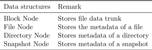
Table 3.1: Primary Data Structures
Data structures Remark
Block Node Stores file data trunk
File Node Stores the metadata of a file Directory Node Stores metadata of a directory Snapshot Node Stores metadata of a snapshot
tured by the VFS module in the kernel and then be routed to FUSE. FUSE will then pass on
the file system call to the Kabi file system, get the return value from Kabi file system and then pass it back to the VFS module. On the other side, the MongoDB Java driver is used by the
system abstraction module to communicate with the MongoDB daemon process.
3.2
File System Initialization
At file system initialization, parameters related to this particular instance of Kabi file system
should be provided and stored in a MongoDB collection. For example, these parameters include the size of a data block and the name of the MongoDB collection used by this instance of Kabi
file system. These parameters are immutable once the file system is established.
Figure 3.2: System Diagram of Kabi File System
The configuration file will contain parameters related to this mount operation. The file has three
sections: FUSE options, MongoDB options, and file system client options. These parameters are important for the file system to know about the data source (such as the IP address and
server status of MongoDB server), the snapshot to be mounted, and the name of the MongoDB
collection where the initialization parameter is stored. These parameters only affect this mount operation on the local machine and will not have influence on the remote server.
3.3
Nodes and Objects
Nodes are the primary data structures in the Kabi file system. A node is stored as a document
in MongoDB and each type of node corresponds to a collection in MongoDB. Table 3.1 shows
all four types of nodes used in the Kabi file system. A node may have a complex structure. A member of a node structure can be as simple as an integer, but also can be as complex as
a set of nested objects. For the convenience of discussion, complex substructures (embedded
or nested objects [14]) will be discussed separately. These substructures are part of the node structure. They will be called “object” instead of “node”. The section object and the subnode
Figure 3.3: Basic Entities and Relations
be discussed in Chapter 4.
Figure 3.3 demonstrates a basic view of nodes and their relations in the Kabi file system.
The view consists of four node types and one object type: the block node, the directory node,
the file node, the snapshot node, and the patch object. Nodes and objects are refering each other. They form a directed acyclic graph.
3.3.1 Block Nodes
Block nodes are representations of some fixed-size data. The size of data represented by a block
node is called representation size or rep-size for short. The rep-size is an immutable positive integer which is determined at file system initialization. Different instances of Kabi file system
can have different rep-sizes. Although rep-size is fixed, a block node does not have to actually store that amount of data. If the size of data stored in the block node is smaller than rep-size,
i.e., there is insufficient data, the file system logic module will get the data with ‘\0’ padding from the storage abstraction module. The fixed rep-size design is to ensure that each rolling hash (discussed later in Chapter 4) corresponds to exactly one block node since the rolling hash
function is a function on fixed length data. On the other hand, the variable actual-data-length is
designed to make “truncated sections” (also discussed in Chapter 4) more efficient. In addition to the data field, another important field is the 128-bit hash of the byte string. This field is
reserved for deduplication and will be discussed in later section. The structure of a typical block
Table 3.2: Fields in Block Node
field remark
ID the 128-bit SHA hash of block data data the block data
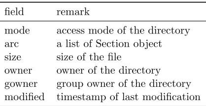
Table 3.3: Fields in File Node
field remark
mode access mode of the directory arc a list of Section object size size of the file
owner owner of the directory gowner group owner of the directory modified timestamp of last modification
3.3.2 File Node and Section Object
Each file in the Kabi file system is associated with a file node. The file node stores the metadata
of the file. In the Kabi file system, the actual data of the file is stored in sections with variable length. Each section is represented through a “section object”. A file node consists of an array
of section objects and other fields. By connecting the content of data sections in order, the file
system recovers the content of the file from data section array. Each data section corresponds to exactly one block node and the block node may contribute part of its binary data to the
data section instead of entire binary data stroed in that node. If only a proportion of the node data is used by the section, two integers should be provided to locate the starting index and
ending index. This design is for reusing the block node in the snapshot system. Using such a
design, if a block node is partly overwritten and it original data is referenced by the snapshot subsystem, we can reuse part of the original data. Figure 3.4 shows a file node that consist of
3 data sections: the first data section contributes all 4 bytes of corresponding block node data,
the second section gets 2 bytes from its corresponding block node and the last section receives the first 2 bytes from its corresponding block node. The detailed structure of a file node is
Figure 3.4: File Node, Section Object and Block Node
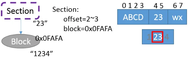
Figure 3.5: Section Object and Block Node
As mentioned above, a file node contains an array of section objects. Each section object is a
substructure of file node and represents a section of file data. It consists of three fields as shown
in Table 3.4: an object ID referring to the associated block node, an integer value specifies the number of omitted leading bytes, and another integer value specifying the index of last byte in
block node. In the example shown in Figure 3.5, for the second block, the number of omitted
leading bytes is 1, and the index of the last byte in block is 5.
The size field stores an integer value, representing the size of this file in bytes. When reading
the file, ‘\0’ padding will be appended to the end of read buffer if the value in the “size” field exceeds the total number of bytes in its data sections. On the contrary, if the total number of bytes in data sections exceeds the value of the “size” field, data will be truncated and the
bytes that exceeds the size will not be provided to the user program. This design allows faster
Table 3.4: Fields in Section Object
field remark
ID ID of corresponding block
roll the 32-bit rolling hash of block data
omit specify how many leading bytes in block will be omitted offset the offset of last byte in this section
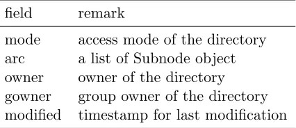
Table 3.5: Fields in Directory Node
field remark
mode access mode of the directory arc a list of Subnode object owner owner of the directory gowner group owner of the directory modified timestamp for last modification
3.3.3 Directory Node and Subnode Object
A directory node corresponds to a directory in the file system. Directory nodes share a similar structure with file nodes, they also consist of several fields that store the metadata and an
array of subnode objects. The subnode object is similar to the section object in file node. A
subnode object corresponds to an “item”(a file or a directory) under that directory. A subnode object contains a reference to the “item” and a string represents the display name of the “item”.
Depending on the type of node that a subnode object is referencing, the “item” can be a file
under the directory or a sub directory.
Other important data structures are the snapshot node and the patch object. These two
structures are related to the snapshot system and will be discussed in Chapter 4.
3.4
File System Operations
The file system logic module in Kabi file system decomposes the FUSE file system calls to
stan-dard node operations (these operations are defined by the internal interface). Most of the FUSE file system calls have been implemented in the Kabi file system, some of those implemented
calls include access(), getattr(), read(), write(), rmdir(), unlink(), mkdir(), truncate(), flush(),
ad-Table 3.6: Fields in Subnode Object
field remark
name display name of the file or subdirectory ID ID of the file or subdirectory
dDataNode2db() and patch(). The former three methods write a node object into the database as a new node. The patch() method replaces an existing node with its new version.
3.4.1 Read Operations
Three important read file system calls are access(), getattr(), and read(). The access() function
tests the existence and permission settings of a file or a directory in the file system. The getattr() function call returns the meta information about a file or a directory. The read() function reads
and returns binary data of given length starting at a specified offset.
The first step of a read operation is finding the target file node or directory node by its path. In order to do so, the file system parses the given path and finds all corresponding nodes
on the path in order from the root directory to the target. The file system will start with the root directory, continue traversing subnode lists and find directories on the path one by one
until the algorithm hits the target or finds it nowhere.
This strategy is generally not satisfactory. It may lead to a performance bottleneck in read operation when a target file lies deep in the directory tree. In such cases, a simple access() call
will be mapped to a sequence of database queries on directory nodes. To solve this issue, a
cache that stores the path and corresponding node ID is introduced. The path cache can be a in-memory-cache (when the file system is mounted locally with FUSE’s single thread option) or
a database cache (when multiple threads or client for consistency). With the help of the path
cache, the file system no longer needs to traverse and find every directory node on the path. The path cache is a move-to-front dictionary [11], which maps a path string to an integer
which represents an ID of a directory node or a file node. The cache has a fixed capacity and
assumes temporal locality in the access pattern. It uses move-to-front algorithm to keep the frequently accessed item in the cache and remove those items that have not been accessed for
long. The cache also assumes spatial locality: when accessing a file or a directory, not only is
the file or directory itself is cached, but all directories on the path (i.e., its parent and ancestor directories) also go into the cache. Thus, when touching contents under the same directory
later, the file system can quickly find its parent node.
Figure 3.6: Copy-on-Write
will traverse the section object array to find the ID of block node associated with the read call.
For each block node, the file system will then calculate the begining index and ending index of
the bytes of the block content that will be copied to the read buffer. At last the file system will query MongoDB for block nodes and copy the requested data to buffers.
3.4.2 Write Operations
The Kabi file system only writes a file on request (either a close request or an explicit flush request). It uses write() call to write data into a file from some offset. Other write calls like
chmod(), chown(), mkdir(), unlink() and rmdir() change the meta information of a directory
or file.
copy-on-Figure 3.7: Write Buffer
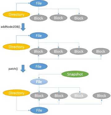
write strategy when an overwrite operation is requested. Thus, when an overwrite operation to
a file node or a directory node is requested, the file system will make a local copy of the node
and apply the modification to this local copy. The file system will then upload that copy to the remote machine and attach it to its parent directory, replacing the original node, as shown
in the Figure 3.6. In this way, the old version of the node can be saved for snapshot and a
read operation will not accidentally read in a node that is in an incomplete state. As shown in Figure 3.6, during this process, we use the addNode2DB() operation to add a new node and
use the patch() method to replace the old version with this new node.
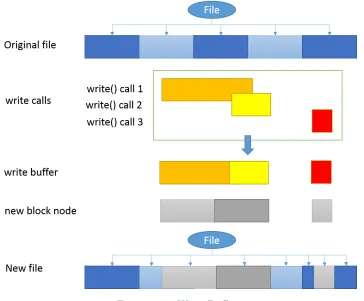
When writing a file, the write request will not immediately flush data into the persistent storage. Instead, the data will be written into a local write buffer. Data in write buffer will be
merged and subsequent writes may overwrite previous buffered data when there is an overlap. When the file system receives a close() call or an explicit flush() request, data in buffer will be
truncated into blocks and uploaded to remote servers. The content in the local buffer may be
lost due to a system failure, but a user can always use a fsync() or fdatasync() as suggested in POSIX standard to flush important data to remote. The flush process is atomic, which is
During a flush, a data section (section object) may be unaffected, partly overwritten or
entirely overwritten. A block node will be detached from the file if its corresponding data section has been entirely overwritten. The data section object will be truncated if this section
is partly overwritten. If a section is truncated, the starting offset and the ending offset will be
updated to reflect the change. However, the block node will remain the same. Figure 3.7 shows the routine to write a file.
Compared to a traditional copy-on-write snapshot file system, which copies and overwrites
the entire block whenever there is a byte change, this design makes use of the old block. Because the old block will be kept for snapshot, reusing it in current view may save some storage.
However, there is a tradeoff between these savings and the overhead of such design. Each
data section object requires 224 bits of storage to store its SHA hash, rolling hash, begining index and ending index, each block node requires 128 bits to store its SHA ID. There are
many cases where this overhead worth it. In an extreme case, if we overwrite two bytes at the
boundary of two blocks right after a snapshot is taken, two new blocks must be created in a classic copy-on-write snapshot system but only one 2-byte block will be added to Kabi file
system. With a block size of 2,048 bytes and a file size of 20,480 bytes, the savings in this case
is 3,798 bytes.
3.4.3 Consistency
Maintaining consistency is an important task for a file system. During a write call, the file
system may enter an inconsistent state before the write call successfully returns. A file system should prevent a read call from reaching the inconsistent state to keep consistency. There are
many ways to keep a file system consistent. Some of file systems use a lock to prevent a read
operation when the file system is processing a write call. In our implementation, we use the atomic document update to prevent the inconsistent state.
Figure 3.8 and 3.9 demonstrate how we prevent the inconsistent state. The write process
can be divided into two steps. The first step is upload. In this step we upload new data nodes and the new of metadata nodes which will be affected by the write call. During this process,
read operations may come in at any time and observe the old content because all new nodes
are not connected to the directed graph and all old nodes have not been modified. The second step is atomic update. This step is always atomic, which is guaranteed by MongoDB. In this
step, the file system will change affected references from referring the old node to new node.
When a write operation only affects one snapshot, the file system will directly replace the old node with the new node by updating the referring reference as shown in Figure 3.8. When a
Figure 3.8: Consistency - Within a Snapshot
node in the atomic update step.
3.4.4 Deduplication
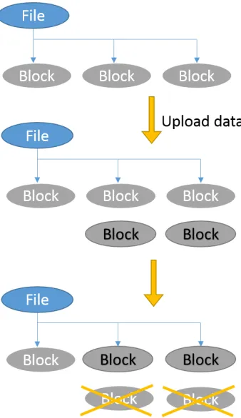
Block node creation is an expensive operation as it requires storage space on the remote machine and all data must be transferred to remote. Unfortunately, block node creation occurs very
frequently. it happens when creating a file, when appending a file, and even when writing a file.
We found that not all block node create operations are necessary. Consider the following scenario, when a user program is trying to create a copy of a file, the program will read in all
data from the file to a buffer and then write the data in the buffer to another newly created
file. As a result, the file system will experience a series of read() and write() function calls, not aware that these function calls are related. The file system has no way to know whether or not
the block node it is going to write already exists in the file system and the node can be reused.
By using the SHA hash as the block node ID, it becomes possible to find and eliminate blocks that contain duplicate data. Before a block of binary data is uploaded, the file system
Figure 3.9: Consistency - Across Snapshots
system will stop uploading the block node and directly return the ID of the existing node
with the same hash value. In this way, the file system not only can perform a copy operation efficiently but also can save space for duplicate blocks.
3.5
Conclusion
In this chapter, we presented the design of a distributed file system and the design of its modules. We demonstrated an overview of the file system, its basic entities and operations, as well as
Chapter 4
Snapshot
One of the major features in the Kabi file system is the writable copy-on-write snapshot. A snapshot is a point-in-time copy of a defined collection of data [1]. A read-only snapshot is an
immutable copy of the data in the file system at a specified time spot, while a writable snapshot
can be considered as a writable fork of such copy. In kabi File System, the snapshot subsystem is designed as a fundamental component. The “current” view of the file system is also treated
as a special writable snapshot (the latest snapshot in default branch). This snapshot system
focuses on reducing the storage space occupied by snapshots.
According to the Storage Networking Industry Association, three classic snapshot approaches
are: split-mirror, changed block, and concurrent [2] The split-mirror approach copies every byte
from the data source to the snapshot. This process is time consuming and hence it usually requires planning in advance. The changed block approach applies the copy-on-write strategy
on the snapshot. The concurrent approach redirects IO requests to different storage spaces
as-sociated with snapshots. Instead of making a copy and overwriting the copy, write IO requests will be redirected to a separate storage space. Where the read IO requests may be redirected
depends on whether or not the data has been changed since last snapshot.
Our snapshot system uses a strategy that is a mixture of copy-on-write (the chanaged block approach) and redirect IO (the concurrent approach). It uses the enhanced copy-on-write
strategy on the actual data and the redirect IO strategy on metadata. In our snapshot system,
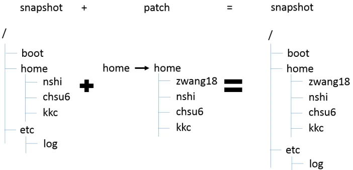
all snapshots (except for one) log the changes since the prior snapshot. The snapshot system can then recover the content of a snapshot based on related snapshots and the log of changes,
as shown in Figure 4.1. The only exception is a special snapshot called the “head snapshot”
which references the content of the entire file system. Other snapshots are called referencing snapshots. Each referencing snapshot consists of a reference to another related snapshot and
Figure 4.1: Snapshots and Patches
4.1
The Snapshot Tree
The snapshot system in the Kabi file system uses an approach based on patches. A similar
approach that is adopted by the ext3cow file system uses a reserved field in inode to reference the previous version of inode, as shown in Figure 4.2. One of the advantages of the patch
based approach is that it supports tree structured snapshots and writable snapshots. With tree
structured snapshots, a user can fork the file system to keep multiple “current” versions of the file system at the same time.
Snapshots in the Kabi file system are represented by snapshot nodes. These snapshot nodes
form an up-tree. In an up-tree, every child points to its parent. Figure 4.3 shows an example of a snapshot tree. The right bottom node (node H) in the figure is the root of the tree. The root
of the snapshot tree is always the head snapshot.
Initially, the file system contains a default writeable snapshot node (node H in Figure 4.3) representing the current view of the file system. This special snapshot called the head snapshot
is the root of the snapshot tree and the only snapshot node that does not reference any other
snapshot. For the initial state, writes to the file system go directly into the head snapshot. After a snapshot is taken, a new snapshot node (node 1 in Figure 4.3) is created referring
to the head snapshot node. Subsequent write operations will not only write data into the head
snapshot, but also submit patches to all snapshots connected to head snapshot, so as to reflect the difference between snapshot node 1 and its referencing node H.
Branching a snapshot creates a writable copy of an existing snapshot. The branching
Figure 4.2: Snapshots in SnapFS
Figure 4.3: An Example of Snapshot Tree
node 2 (the existing snapshot).
In the snapshot tree, each writable snapshot corresponds to a branch. A branch consists of the writable snapshot (the current status of the branch) and its historical snapshots (the history
of the branch). The main branch is the branch where the head snapshot node lies. Figure 4.4
shows the idea of branch. In the example, there are two branches in this 5-node snapshot tree. Node H is the root of the up-tree so it represents the head snapshot. Hence node 1, node 2, and
node H form the main branch. In the figure, nodes on the left correspond to older snapshots
and nodes on the right correspond to more recent snapshots. Therefore in main branch, node 1 is the oldest snapshot while node H represents the latest state. Node 1 and Node 2 form
the history of main branch and node H is the current view of main branch. Node 4 is another
writable snapshot and it belongs to a side branch. The side branch consists of node 1 (the oldest), node 2 (the second oldest), node 3 (the third oldest), and node 4 (most recent). Note
the arrows between nodes reflect the referencing relations between snapshots, not the order of
Figure 4.4: Branches
4.2
Snapshot Nodes and Patch Object
As mentioned in previous sections, there are two types of snapshot nodes in this file system, namely the head snapshot node and the referencing snapshot node. The head snapshot is a
special snapshot in the file system. It is the root of the up-tree and it does not reference
any other snapshots. Instead it stores the entire content of current view in the main branch by referencing the directory node of the root directory. In this way, read access to the head snapshot
node is straight forward and faster than any other snapshot. Because of this property, the head
snapshot is recommended to be used to represent the most frequently accessed snapshot or the current state of the default branch.
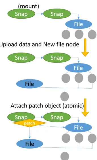
On the other hand, a referencing snapshot does not reference its own root directory, but it does keep a reference to another snapshot node and an array of patch objects. The array
of patch objects represents the difference in content between this referencing snapshot and the
referenced snapshot. Reading a referencing snapshot will first read the file system content in the referenced snapshot and then lookup the patch list to find out if the content has been changed
in this snapshot. To write data, the referencing snapshot uploads the changed nodes into the
database, builds a patch object with both IDs, uploads and attachs the patch to the snapshot node in the remote machine. This upload and attach process is atomic and it ensures the file
system is not being left in an incomplete state. Once a referencing snapshot is referenced by
some other snapshot nodes, it becomes a read only snapshot. Figure 4.5 shows the structure of a head snapshot node (right) and the structure of a referencing snapshot (left).
A patch object reflects one or more modifications to a single node. The node can be either
a file node or a directory node. The patch object references a pair of file nodes or directory nodes. The two nodes referred are the target node (original one) and its replacement (changed
one).
Figure 4.6 demonstrates the way the patch system works. Snapshot 1 and 2 demonstrate how a directory changes between snapshots. The directory that is represented by node d2 in
Figure 4.5: Root Snapshot and Non-root Snapshot
Figure 4.6: The Principle of Patches
has a new subdirectory, but the file under that directory remains unchanged. Hence, the target node,d2, and replacement node, d1, have a reference to the same file node but the target node,
d2, has one more reference to a directory node. In the example of snapshot (a) and snapshot (b),
a file changes in both snapshot, its original version is f1, the intermediate version in snapshot
(b) is f2 and the final version is f3 in snapshot (a). In snapshot α and snapshot β, file f3 is
replaced byf2 in snapshot (β) and is replaced byf1 in snapshot (α).
4.3
Snapshot Related Operations
Operations related to the snapshot system are: read the content in a snapshot and make changes
to a writeable snapshot. Making changes to the current view of the file system also involves snapshot write operations as the current view of the file system is also treated as a snapshot in
Figure 4.7: Read a Snapshot
4.3.1 Read Operations
When reading a file or a directory in a referencing snapshot, the file system must do a large number of lookup operations in patch lists to ensure that the file system is referring to the
correct version of the node. For instance, in Figure 4.7, to read the file “/a/d.txt” in snapshot
1, the file system will first read in the “/” directory in the head snapshot which is node 3. Then, the file system transverses all involved snapshots (1 and 2) to see if there is a patch whose target
node is node 3. Since no such patch is available, this means node 3 is the “/” directory node of
all snapshot nodes (1, 2 and 3). After that, the file system will look for the “a” directory under node 3 and corresponding patches. This time there is a directory (node 9) with the display
name “a” under node 3, but there is also a patch to node 9 in snapshot 2. That means node
5 is the “/a” directory node of snapshot H while node 6 is the directory node of snapshot 1 and snapshot 2. Follow the same procedure, we will find that node 8 is the “/a/d.txt” node in
snapshot 2, but for snapshot 1, “/a/d.txt” is represented by node 6.
As one can see, read operations rely on the patch lookup operation. To avoid massive query and traverse operations on all involved snapshots and patch objects on every read operation, a
local patch list will be built and stored as a hash table in memory when a referencing snapshot
node is mounted. The local patch list combines all patches that may be used for a node lookup. In the example shown in Figure 4.8, when mounting snapshot 3, a local patch list that contains
all effective patches in snapshot 3 and 2 is created.
Not all patches in patch lists are effective or will be combined into the local patch list. Because patches come from different patch lists, when combining them together, some patches
can be merged into one and some are unrelated to this snapshot. For instance, in Figure 4.9
snapshot (a) and (b), the replacement node f2 of a patch is also the target node of another
patch, these two patch object can be merged into one local patch. Another example is when
Figure 4.8: Combine Patch Lists
If the mounted snapshot is snapshot (α), the patch in snapshot (β) will be considered ineffective and will be discarded when building the local patch list.
4.3.2 Write Operations
In copy-on-write snapshot systems and redirect IO snapshot systems, a file system entity (block, file, directory) may be referenced one or more times. The referencer can be snapshots or the
“current” view of the file system. If an entity is referenced only once, a write operation to
that entity will be straight forward. This is a write operation within a snapshot. On the other hand, when an entity is referenced more than once, the snapshot system usually needs special
treatment to the write operation. Otherwise, a direct in-place write will affect all referencers. In
the snapshot system, we focus on the latter case. If not otherwise specified, the phrase “write operation” in this section refers to those write calls whose target entity is referenced more than
once.
Figure 4.10 briefly demonstrates how patch objects and snapshots work with write opera-tions. In this example, there are three snapshots. Node H is the head snapshot node representing
the current status of the main branch. Snapshot node 2 represents the initial status and node
1 is the intermediate status of the main branch. Initially, the file system contains three direc-tories “/”, “/a”, “/b” and two files “/a/c.txt”, “/a/d.txt”. In between the initial snapshot and
the next snapshot, file “/a/d.txt” was overwritten so its representing node was changed by a patch. After snapshot 2 is taken, the file “/a/d.txt” was deleted. A new patch was attached to
Figure 4.9: Merge Patches (Local)
Figure 4.11 and 4.12 show how to take snapshots on the main branch and side branches. In
order to take a new snapshot on the main branch, the file system will create a new snapshot node
in between the head snapshot and its adjacent snapshot nodes. This newly created snapshot will reference the head snapshot and have an empty patch list. This new snapshot node will
represent the status of this branch at the time it is created. The current state of the main
branch is still represented by the head snapshot.
To take a snapshot on a side branch, the file system will create a new snapshot node and
attach it to the end of the side branch. The newly created snapshot node will reference the latest
snapshot on this branch and have an empty patch list. After being attached to the branch, this snapshot will become the current status of this branch.
When writing a snapshot, other than the head snapshot, the Kabi file system will submit
new patches to that referencing snapshot to reflect the change. In the first example shown in Figure 4.13, the file system is writing the head snapshot in the main branch. It is replacing
node X with its newer version Y. Node Y will replace node X directly in the head snapshot. In
order to keep its previous version “X” in snapshot 2, a “reverse” patch object (Y-to-X) will be submitted to revert node Y back to its original version X. In this way, the head snapshot will
have the new version Y while all other snapshots keep the old version X. In the second example,
the file system is trying to replace node X with its new version Y in snapshot 3. Compared to the first example, the file system now can simply submit a X-to-Y patch to snapshot 3. In the
Figure 4.10: Example - Create Snapshot after Write
Figure 4.11: Take Snapshots on Main Branch
a branch based on that internal node and writing to that branch.
To create a branch based on the head snapshot, it is recommended to create a dummy snapshot first and then fork from that dummy node, rather than branching the head snapshot
directly. This is because a write operation to the head snapshot will submit patches to all
snapshot nodes connected to the head snapshot node. Hence, we wish to limit the number of snapshots connected to the head snapshot. If we fork the head snapshot directly, there will be
multiple snapshot nodes connected on to the head snapshot node. Figure 4.14 demonstrates
this issue. In the upper case, with dummy snapshot node (node 2), a write operation to head snapshot (node 0) only submits a patch to the dummy node. But in the lower case, when there
is no dummy node, a write operation to the head node has to submit two identical patches to
node 1 and node 3.
Figure 4.12: Take Snapshots on Side Branch
Figure 4.13: Write a Snapshot Node
patch associated with it. For example, a patch replacing node 0 with node 1 and another patch replacing node 1 with node 2 can be merged into one patch. This happens when a node is
modified multiple times in one snapshot. For time and space efficiency, it is better to merge
these patches into one patch.
4.4
Enhancing Copy-on-Write and Deduplication
The copy-on-write strategy and the file system deduplication improve space efficiency of the file system. File system deduplication finds and eliminates duplicated blocks and files while the
Figure 4.14: Branching Root Snapshot Node Directly
Figure 4.15: Classic Copy-on-Write
4.4.1 Motivation
A classical copy-on-write snapshot system applies copy-on-write at block level. As shown in Figure 4.15, unchanged blocks will not be copied to the snapshot.
However, this is not always ideal. In many use cases, like insertion or deletion, a write
operation only affects a few bytes instead of a whole block. But a classic file system rewrites all successor blocks in these scenarios. A classic snapshot system makes copies for all successor
blocks despite the fact that only very few bytes are changed. Figure 4.16 addresses this issue.
In this example, a byte is inserted into the file at offset 8. In a classical copy-on-write snapshot system, two successor blocks are treated as changed blocks and get copied. However, the data
in those blocks did not change. They just got moved one byte forward. In the figure, we also
demonstrate a potentially better approach.
To solve this problem, we have to make the file system aware of the true intention of the user
program. This is not straightforward because the POSIX standard uses only one file system
Figure 4.16: Issue in Classic Copy-on-Write
rewrite a part of a file.
If a user program intends to insert a byte right in the middle of the file, a POSIX file system will receive a set of write calls to rewrite all later blocks in order to move the original data 1 byte
forward. The same behavior can also be observed when the user program tries to rewrite the
latter half of the file. It is difficult for the file system to distinguish these two scenarios (rewrite and insert). Access patterns can be used to provide some clue of the intention of an operation
(i.e., an insertion usually results in a truncate call followed by a series of write() calls), but it
is not an ideal solution as it depends on how the user program behaves. Therefore, our major challenge is to identify the true intention of a write operation, whether or not it is an insertion
or an actual rewrite. In the next chapter, we will show how to accomplish this goal by applying
the rsync algorithm [32].
4.4.2 The rsync algorithm
As discussed in the previous section, in order to identify duplications in a better way, we need
to have a mechanism to compare the data to be written into the file and the original data. The rsync algorithm was originally designed for the efficient update of data over a high latency and
low bandwidth link. Compared to the brute force search or string search algorithms, the rsync
algorithm is much faster in practice and requires less data exchange between the remote server and the local machine. These features make it suitable for a distributed file system. Because
either a time consuming file system or a high bandwidth consumption file system will become
Figure 4.17: Identifying the Intention of Write Operations
The basic flow of the original rsync algorithm is to split the remote file into blocks of length
S, calculate their rolling checksums, and then send the checksums to the local machine. The
local machine will search through the local file to find all blocks of length S (at any offset, not just multiples of S) that matches a received rolling checksum. This can be done in a single
pass very quickly since the rolling checksum algorithm only requiresO(1) time to compute the
checksum at offset kif the checksum at offset k−1 is given.
4.4.3 Enhancing the Space Efficiency
The Kabi file system uses the rsync algorithm to enhance the space efficiency of snapshots. It
assumes that in most cases two different versions of the same file will share part of their data. In the Kabi file system, a section object in a file node contains not only the reference to
the corresponding block, but also the rolling checksums of the block data. Before flushing the
write buffer, the local machine calculates the rolling checksums of data blocks at all possible offsets. The file system compares these rolling checksums with those fetched from remote. If a
match is found, the file system then double check their SHA-1 hash to confirm that it is indeed
a duplication.
Once all data blocks have been examined, the local machine will send IDs of duplicated
blocks and all remaining data back to the remote server.
During this process, the computational overhead is only the calculation and the matching of rolling checksums. An important property of rolling checksum algorithm is that successive values
can be computed in O(1) time. Thus, it ensures that all rolling checksums can be calculated in
Figure 4.18: Using Rsync to Find Unchanged Blocks
4.5
Conclusion
In this chapter, we present the basic idea of this snapshot system and discuss some
implemen-tation details of the snapshot subsystem in the Kabi file system. We demonstrated our efforts
Chapter 5
Performance
As an important resource management component in the operating system, a file system has a large influence on the operating system in terms of performance. In this chapter, we will
evaluate the performance of the design. We will be focusing on the time efficiency of the file
system and the space efficiency of the snapshot subsystem.
5.1
File System Benchmark
In this section, the performance of the Kabi file system is evaluated using the file system
benchmark tool “postmark” [18]. Postmark’s default benchmark settings are used in all tests cases. The default settings include 500 stand-alone file creations, 264 file creations mixed with
transactions, 243 file reads, 257 file appends, and 764 file deletions.
We also compare our proof-of-concept implementation with other popular file systems. In our implementation, we use JNA [22] as the Java language binding for FUSE.
FUSE-JNA is designed to support fast development for concept file system. However, it is not the best choice in terms of performance. FUSE-JNA creates a Java thread for every file system call,
uses JNA to communicate with the fuse library, and switches between the kernel space and the
user space very frequently. Hence, the overhead of using FUSE-JNA is significant. In order to eliminate this overhead in comparison, other file systems will be wrapped with FUSE-JNA in
the test.
Two sets of tests are performed: the local test set and the remote test set. In the local test set, the client of Kabi file system and its backend MongoDB are deployed on the same machine.
The performance of the Kabi file system is compared to the perfromance of a Ext4 file system
on a same disk. The testing environment includes a 64-bit Ubuntu 12.04LTS operating system, one 2.4GHz 6MB cache Intel i7-2760QM CPU, a total of 24GB DDR3 1333MHz RAM, and a
Table 5.1: File System Performance Test
Scenario Tests1
File System Test Set Creation4 Creation5 Read Append Delete
Kabi local 83 33 30 32 47
Ext42 local 96 49 53 46 88
Kabi remote 55 29 27 28 36
NFS2,3 remote 45 26 24 25 36
1Test results are in “operation per second”, the larger the better. 2The file system is wrapped with FUSE-JNA.
3The client uses NFS to mount a directory on remote Ext4 partition. 4Stand-alone creation (column 3): this test does nothing but create files 5mixed with transactions (column 4): these creations are performed
be-tween other operations (Read, Append, Delete)
deployed on different machines. The remote test uses Amazon AWS service to build a standard testing environment. Both machines use Amazon EC2 t2.micro instance with one 8GB EBS
volume and connect to a 10 Gbps local area network. The operating system is a standard 64-bit
Ubuntu image provided by Amazon AWS. The remote test set compares Kabi file system with a FUSE-JNA wrapped NFS.
The file system test results are shown in Table 5.1. These results show that, when used as a
local file system, the Kabi file system has a performance lower than but close to the performance of Ext4. As a distributed file system, its performance is comparable to the performance of NFS.
5.2
Efficiency of Snapshot and Deduplication
This section will focus on the space efficiency of the snapshot system. We are going to measure
the space efficiency of the snapshot system by estimating the average space cost of a snapshot
of a single file. We will study the influence of two factors against the space efficiency. The first factor is the ratio of file size against block size. The second factor is the proportion of “truncated
sections” in the file. “Truncated sections” refer to those sections that are not referring to a whole
block. For example, the third section in Figure 4.18, the second and third section in Figure 3.4 are all truncated sections.
We follow the steps below to estimate the storage space occupied by a snapshot (all random
numbers follow a uniform distribution. The size of space is calculated by adding up the size of all fields in all newly created nodes):
2. Generate a file with sizeF.
3. Fill the file with sections and let a certain proportion (P) of the sections be truncated.
4. Take a snapshot of the file and make two side branches.
5. Switch to side branch 1, insert random number of bytes into the file at random offset.
6. Take a snapshot on side branch 1 and calculate the total space occupied by this snapshot.
7. Switch to side branch 2, overwrite random number of bytes from random offset.
8. Take a snapshot on side branch 2 and calculate the total space occupied by this snapshot.
9. Repeat above steps 10,000 times and compute the average value.
Table 5.2 shows two sample results of such experiment. The first three columns in the
table are the variables of the experiment. The next four columns are the data gathered from
experiments. For example, the column labeled classic under overwrite section means write oper-ations are all overwrites and the algorithm used by snapshot system is the classic copy-on-write
algorithm.
The first row in Table 5.2 represents an experiment on a Kabi file system whose block size equals to 128 bytes. The target file is a 12,608-byte file where 3% of all sections are truncated.
The second row is for a file 10 times larger. In the first experiment, the result shows that on
average it takes a classic copy-on-write snapshot system 3,288 bytes to take a snapshot after an overwrite operation. It takes 103 bytes more for a Kabi file system to take a snapshot under
the same condition. When it comes to insertion, on average it only takes the Kabi file system
3,256 bytes to take a snapshot after an insertion while it requires almost 2 times more space for a classic copy-on-write snapshot system to do so. In order to compare data between first
and second experiment, we will use normalized data instead of absolute values in all tables here
after. The normalization is based on the file size.
This result is not difficult to explain. Because there is not much duplicated data in the
overwrite scenario, SHA hashes and rolling checksums become overheads. This makes the per-formance of the Kabi file system slightly less than the classic approach. But in the insertion
scenario, lots of duplicated data can be found. The rsync algorithm is able to find the
duplica-tions to improve the efficiency. On the contrary, the classic approach cannot detect and make use of these duplicated data. So the Kabi file system has a better performance when it comes to
insertion. The Kabi file system is optimized for efficient insertion. The test shows that it does
Table 5.2: Sample Result of the Experiment
experiment variables overwrite results insert results block size file size truncated section classic Kabi classic Kabi
128 12608 0.03 3288 3391 9530 3256
126080 31722 32205 94867 32557
5.2.1 Block Size and File Size
The block size and the file size also influence the efficiency of a snapshot system. A high
file-size-to-block-size ratio usually means fine-grained blocks. A classic copy-on-write snapshot will
get better efficiency with a fine-grained block. Consider the extreme case where the file-size-to-block-size ratio is 1. In other words, the file contains exactly one block. Then any change means
a complete rewrite to the file by classic copy-on-write strategy. This is shown on Table 5.3
column classic under section overwrite and section insert where the overhead of classic strategy decreases as file-size-to-block-size ratio increases.
However, column Kabi under insert section shows that there is no obvious relationship
be-tween file-size-to-block-size ratio and efficiency when doing an insertion in the Kabi file system. One reason for this could be the Kabi file system can truncate block into smaller sections freely
as shown in Figure 3.7. Therefore the Kabi file system can have fine-grained sections even
though the file system sets a large block size.
The data in column Kabi under overwrite section reflects the fact that an increase in
file-size-to-block-size ratio will result in an improvement in efficiency. The reason is that the proportion
ofextra metadata will reduce as the file size increases. For example, an overwrite operation can result in at most two additional sections added to the file node. This means an extra 56-byte
overhead in metadata. Such overhead is large (almost 8%), compared to the file size (704 byte).
On the other hand, if the file size is 14,008 bytes, this overhead (metadata of 2 extra section) can be omitted (about 0.4%).
5.2.2 Truncate Ratio
The rsync algorithm identifies duplications in local buffer and remote sections. It uses the rolling checksums of sections to find duplications. But a truncated section does not have a valid rolling
checksum. Thus it cannot be benefited from the rsync algorithm. We can infer that, the more
truncated sections we have the less efficient snapshot system and file system deduplication will be.
Table 5.4 supports this inference. It shows the relationship between the efficiency and