Division 2
ELEVATED TEMPERATURE DESIGN AND INTEGRITY EVALUATION
OF A LARGE-SCALE SODIUM TEST FACILITY, STELLA-2
Hyeong-Yeon Lee1, Seok-Kwon Son2, Ji-Young Jeong1, Min-Gu Won3, and Nam-Su Huh4
1 Principal Researcher, Korea Atomic Energy Research Institute, Rep. of Korea
2 Post MS, Korea Atomic Energy Research Institute, Rep. of Korea
3 Ph.D Candidate, Sungkyunkwan university, Rep. of Korea
4 Associate Professor, Seoul National University of Science and Technology, Rep. of Korea
ABSTRACT
A large-scale sodium test facility of STELLA-2 is to be constructed by 2019 for integral effect tests, and a detailed design of the test facilities is underway at the Korea Atomic Energy Research Institute (KAERI). Elevated temperature design (ETD) evaluations were conducted for the model reactor assembly of 316L stainless steel and intermediate heat exchanger (IHX) of Gr.91 steel according to the ETD codes of RCC-MRx and ASME Subsection NH. The integrity of the sodium test facilities was confirmed based on the design evaluations according to the design codes, and conservatism in the design codes was compared.
INTRODUCTION
The objectives of the STELLA-2 sodium test facility are integral effect tests for verification of the dynamic plant response associated with a synthetic review of the key safety issues and safety analysis code validation with the obtained test database. The reference plant of STELLA-2 is a PGSFR (Prototype Generation IV Sodium-cooled Fast Reactor) (Lee, 2017, IAEA, 2012). A detailed design of STELLA-2 is underway at KAERI (1). Securing the structural integrity for the intended severe design transients is very important because the planned tests in the sodium test facility can be successfully conducted only in a mechanically safe system.
The sodium test facility will be subjected to high thermal loads with a core outlet temperature of
550°C at atmospheric pressure. The main components subjected to high temperature are the model reactor
internals of 316L stainless steel and an intermediate heat exchanger (IHX) of Mod.9Cr-1Mo (ASME Grade 91 steel). An elevated temperature design (ETD) of the STELLA-2 system was conducted as per RCC-MRx rather than ASME Section III Subsection NH (hereafter ASME-NH) because high-temperature material properties are available for 316L stainless steel in RCC-MRx, and not available in ASME-NH (Lee, 2016). 316L stainless steel is a material used in high-temperature test facilities because it is a readily available and economical heat-resistant material.
For ETD evaluations of the high-temperature components, a web-based design evaluation program of the HITEP_RCC-MRx (Lee et al., 2017) was developed for a design-by-analysis for ETD evaluations according to RCC-MRx. The material properties of RCC-MRx are embedded in the program, and a third-party program verification was conducted.
DESIGN EVLAUTION OF THE STELLA-2 COMPONENTS
and sodium storage tank), and piping systems. Design evaluations of the piping system in STELLA-2 were conducted in a previous study by Son et al. (Son, 2016).
The thermal design transients for the model RV and RI are shown in Fig. 2, which has been selected in a conservative manner, and the transients for IHX are the same with those of the model RI.
Figure 1. Schematics of the STELLA-2 test facility.
(a)
Transients for model RV (b) Transients for model RIand IHX
Figure 2. Design transients of model RV, RI and IHX
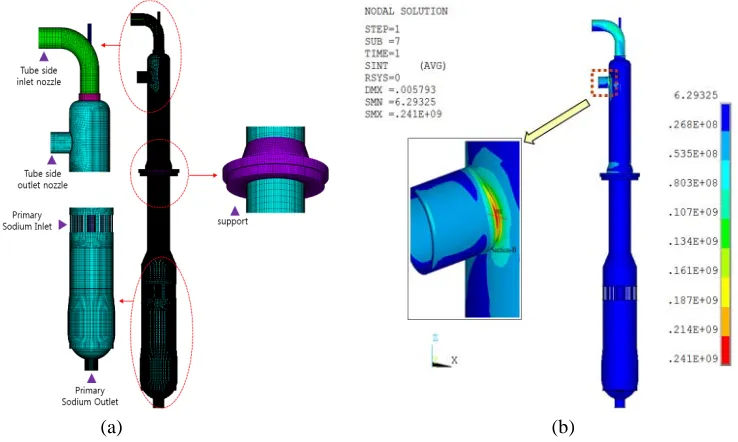
A 3D solid model of the model reactor assembly with a number of main components supported on the reactor head is shown in Fig. 3(a). The 3D model of IHX is shown in Fig. 4(a). Heat transfer analyses and thermal analyses for both components were conducted. The profiles of the stress intensities for the reactor assembly and IHX are shown in Fig. 3(b) and Fig. 4(b), respectively. The critical locations of the redan corner in Fig. 3(c) and secondary sodium nozzle part of Fig. 4(b) subjected to the high temperature of the creep regime were selected, and elevated temperature design evaluations were conducted according to RCC-MRx.
Design evaluations for the redan corner point were conducted according to RCC-MRx and NH. The material of redan is 316L stainless steel. The material properties of 316SS were used in ASME-NH because 316L properties are not available in ASME-ASME-NH unlike RCC-MRx. The evaluation results for creep-fatigue damage show that both creep damage and fatigue damage were negligibly small, as shown in
200°C
time (hr) 150h
500°C
3 hr
200°C
time (hr) 150h
550°C
Fig. 5. Although the materials for redan are different in the two codes, the evaluation results show that the evaluation results of RCC-MRx are less conservative than those of ASME-NH.
The design evaluation results of IHX are shown in Table 1 for the secondary outlet nozzle part of IHX. As shown in Table 1, all design limits of the load-controlled stress, inelastic strain, and creep-fatigue were satisfied. The material of IHX is Gr.91 steel, and it is well know that the design evaluations of ASME-NH are overly conservative, especially for a creep-fatigue damage evaluation in Gr.91 steel (Lee et al., 2012). As shown in Table 1, creep damage and fatigue damage were negligibly small under the intended design transients of Fig. 2.
(a) (b) (c)
Figure 3. Schematic of model RV & RI, profiles of stress intensities under thermal loads
(a) (b)
Figure 4. Evaluation results of creep-fatigue damage for redan corner
Table 1: Design evaluation results of IHX nozzle part according to RCC-MRx.
CONCLUSION
HITEP_RCC-MRx was developed for reliable and efficient computations on the design limit checking according to RCC-MRx.
ACKNOWLEDGEMENTS
This work was supported by an International Research & Development Program Foundation NRF
grant (2013K1A3A7A03078195) and by a NRF grant (2012M2A8A2025635) funded by the
Korea government (MSIP). Yong-Sun Ju of KOASIS Inc. has contributed in 3D finite element
analysis of the STELLA-2 components in this study.
NOMENCLATURE
P
1: effective primary stress intensity
P
2: effective primary stress intensity of the sum of primary stresses
P
L: local primary membrane stress
P
b: local primary bending stress
P
m: primary membrane stress
S
m: design stress intensity at a given temperature
U
: creep usage fraction
W
: creep rupture usage fraction
Φ
: coefficient on the geometry of the cross section
REFERENCES
Status of Fast Reactor Research and Technology Development. (2012). IAEA-TECDOC-1691, IAEA
RCC-MRx, Section I Subsection B. (2015). Class 1 N1RX Reactor Components its Auxiliary Systems and
Supports, AFCEN.
ASME Boiler and Pressure Vessel Code. (2015). Section III, Div.1, Subsection NH, Class 1 Components
in Elevated Temperature Service, ASME.
Lee, H.Y., Kim, J.B, Park, H.Y. (2012). “High temperature design and damage evaluation of
Mod.9Cr-1Mo steel heat exchanger,” Journal of Pressure Vessel Technology, Transactions of ASME, Vol.134, pp. 051101-1~10, Oct.1.
Lee, H.Y. (2016). “Comparison of elevated temperature design codes of ASME Subsection NH and
RCC-MRx,” Nuclear Engineering and Design, 308, 142-153.
Lee, H.Y., Kim, H.M., Kim, J.B., Jeong J.Y. (2017). “Design and integrity evaluation of a finned-tube
sodium-to-air heat exchanger in a sodium test facility,” Journal of pressure vessel technology, Transactions of ASME, pp.031203-1~13, June.
Lee, H.Y., Won, M.G, Son, S.K and Huh, N.S. (2017). “Development of a program for high-temperature design evaluation according to RCC-MRx,” Submitted, April, Nuclear Engineering and Design. Son, S.K., Lee, Lee, H-Y., Ju, Y-S, Eoh, J-H, Jeong, J.Y. (2016). STELLA-2 Design and Integrity