A Performance Comparison of X.25, Frame Relay
and ATM in High Speed networks-A Review
Kiran R. Barapatre1, Nitin R. Barapatre2, Sanket M.Lichade3, Rahul Lanjewar4
Assistant Professor, Dept. of Electronics & Telecommunication Engg, SBJITMR, Nagpur, Maharashtra, India1
Assistant Professor, Dept. of Electronics Engg, KDKCE, Nagpur, Maharashtra, India2
Assistant Professor, Dept. of Electronics & Telecommunication Engg, PBCOE, Nagpur, Maharashtra, India3
Assistant Professor, Dept. of Electronics & Telecommunication Engg, PICT, Pune, Maharashtra, India4
ABSTRACT: To carry out the real time data with high accuracy and with minimum delay between a set of communication devices high speed network is used, which is based up on the optical fiber technology. It is not sufficient to use the high speed data rate alone, unless there is efficient utilization of the bandwidth of the medium. This paper presents the comparative study of three high speed technologies viz. X.25, Frame relay and ATM. Frame relay and ATM are the variations of basic X.25 technology. Based on the various performance metrics, the comparative study demonstrates that ATM has less delay compared to the X.25 and Frame relay and thus is efficient for transmission of the real time data.
KEYWORDS: High Speed Networks, X.25, Frame Relay, ATM.
I. INTRODUCTION
Today's communication networks are built using digital trunks that are inherently reliable, while providing a high throughput and minimal delay. The traditional approach to packet switching (X.25), used in-band signaling, and includes end-to-end and well as per-hop flow control and error control. This approach results in considerable overhead and has historically been too slow - primarily supporting low-speed terminals at 19.2 kbs and lower.
Frame relay is a packet-mode transmission service that exploits characteristics of modern networks by minimizing the amount of error detection and recovery performed inside the network. Thus, by streamlining the communications process, lower delay and higher throughput is achieved. Besides, it can handle multiple data sessions on a single access line, which means that hardware and circuit requirements are reduced. Frame relay is also scalable - implementations are available from low bandwidths (eg, 56 kbps), all the way up to T1 (1.544 Mbps) or even T3 (45 Mbps ) speeds.
ATM was designed for a network that must handle both traditional high-throughput data traffic (e.g., file transfers), and real-time, low-latency content such as voice and video. ATM uses fixed packet lengths of 53 bytes (5 bytes of overhead and 48 bytes of user data), which is more suitable for voice transmissions. This differs from approaches such as the Internet Protocol or Ethernet or frame relay that use variable sized packets and frames.ATM provides extensive quality of service information that enables the setting of very precise priorities among different types of transmissions (i.e. voice, video & email; services include CBR, VBR, ABR and UBR).ATM is scalable ATM uses a connection-oriented model in which a virtual circuit must be established between two endpoints before the actual data exchange[1]
II. X.25
model.X.25 is one of the oldest packet-switched services available. Each X.25 packets contains up to 128 bytes of data. The X.25 network handles packet assembly at the source device, delivery, and then dis-assembly at the destination. X.25 packet delivery technology includes not only switching and network-layer routing, but also error checking and re-transmission logic should delivery failures occur.X.25 supports multiple simultaneous conversations by multiplexing packets and using virtual communication channels.X.25 was originally designed more than 25 years ago to carry voice over analog telephone lines (dialup networks). Typical applications of X.25 today include automatic teller machine networks and credit card verification networks. With the widespread acceptance of Internet Protocol (IP) as a standard for corporate networks, many X.25 applications are now being migrated to cheaper solutions using IP as the network layer protocol and replacing the lower layers of X.25 with Ethernet or ATM hardware.X.25 is a connection oriented service. It supports switched virtual circuits as well as the permanent circuits. A switched virtual circuit is established between a computer and network when the computer sends a packet to the network requesting to make a call to other computer. Packets can then be sent over this connection from sender to receiver. X.25 provides the flow control, to avoid a fast sender overriding a slow or busy receiver. A permanent virtual circuit is analogous to-a leased line. It is set up in advance with a mutual agreement between the users. Since it is always present, no call set up is required for its use. [1][2]
III.THREE LAYERS OF X.25
The X.25 interface is defined at three levels: The three levels are:
(i) Physical layer (level 1) (ii) Data link layer (level 2) (iii) Packet layer (level 3).
These three layers correspond to the three lower most layers of the ISO-OSI reference model. The physical layer takes care of the interface between a computer terminal and the link which attaches it to the packet switching node.
The X.25 defines the interface for exchange of packets between the user's machine (DTE) and the packet switching node to which this DTE is attached which is called as DCE.
The three layers of X.25 interface are as shown in Fig.(a).
At the physical level X.21 physical interface is being used which is defined for circuit switched data network. At the data link level, X.25 specifies the link access procedure-B (LAP-B) protocol which is a subset of HDLC protocol.
This protocol defines the format, content and procedures for exchange of control and data transfer packets. The packet layer provides an external virtual circuit service.
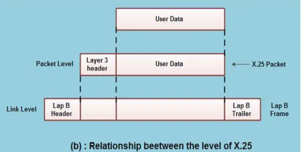
Fig. (b) Shows the relationship between the levels of x25. User data is passed down to X.25 level 3.
This data then appends the control information as a header to form a packet. This control .information is then used in the operation of the protocol.
The entire X.25 packet formed at the packet level is then passed down to the second layer i.e. the data link layer.
The control information is appended at the front and back of the packet forming a LAP-B frame. The control information in LAP-B frame is needed for the operation of the LAP-B protocol.
This frame is then passed to the physical layer for transmission.
Advantages of X.25:
1. Frame delivery is more reliable
2. Frames are delivered in order.
3. Retransmission of frame is possible
4. Flow & error control is provided at both the data link layer & the network layer.
5. X.25 supports the Switched virtual circuits & Permanent circuits
Disadvantages of X.25:
1. X.25 is much slower than Frame relay
2. It has higher overheads.
3. It does not allow transfer of bursty data.
IV.FRAMERELAY
1. Frame Relay is a virtual-circuit wide-area network that was designed in response to demands for a new type of WAN in the late 1980s and early 1990s.
2. Frame relay has evolved from X.25 packet switching and objective is to reduce network delays, protocol overheads and equipment cost.
3. Frame relay can support multiple users over the same line and can establish a permanent virtual circuit or a switched virtual circuit.
4. Packet switching was developed when the long distance digital communication showed a large error rate.
5. To reduce the error rate, additional coding bits were introduced in each packet in order to introduce redundancy to detect and recover errors.
6. But in the modem high speed telecommunication a system, this overhead is unnecessary and infect counterproductive.
7. Frame relay was developed for taking the advantage of the high data rates and low error rates in the modem communication system.
8. The original packet switching networks were designed with a data rate at the user end of about 64 kbps.
9. But the frame relay networks are designed to operate efficiently at the user's data rates upto 2 Mbps. This is possible practically because most of the overhead (additional bits) are striped off.
10.Frame relay also is meant for more efficient transmission scheme than the X.25 protocol.
11.The biggest difference between Frame Relay and X.25 is that X.25 guarantees data integrity and network managed flow control at the cost of some network delays. Frame Relay switches packets end-to-end much faster, but there is no guarantee of data integrity at all. [5] [6]
V. FRAMERELAY FEATURES
1. Frame Relay operates at a higher speed (1.544 Mbps and recently 44.376 Mbps).This means that it can easily be used instead of a mesh of T-I or T-3 lines.
2. Frame Relay operates in just the physical and data link layers. This means it can easily be used as a backbone network to provide services to protocols that already have a network layer protocol, such as the Internet.
3. Frame Relay allows bursty data.
4. Frame Relay allows a frame size of 9000 bytes, which can accommodate all local area network frame sizes. 5. Frame Relay is less expensive than other traditional WANs.
6. Frame Relay has error detection at the data link layer only. There is no flow control or error control. There is not even a retransmission policy if a frame is damaged; it is silently dropped.
7. Frame Relay was designed in this way to provide fast transmission capability for more reliable media and for those protocols that have flow and error control at the higher layers.
VI.FRAME RELAY ARCHITECTURE
Frame Relay provides permanent virtual circuits and switched virtual circuits. Figure shows an example of a Frame Relay network connected to the Internet.
Figure: Frame Relay network
Frame relay can provide two types of virtual circuits. 1. Permanent Virtual Circuits (PVC).
2. Switched Virtual Circuits (SVC).
1. Permanent Virtual Circuits (PVC).
Frame Relay is a virtual circuit network. A virtual circuit in Frame Relay is identified by a number called a data link connection identifier (DLCI).
A source and a destination may choose to have a permanent virtual circuit (PVC). In this case, the connection setup is simple. The corresponding table entry is recorded for all switches by the administrator (remotely and electronically).
PVCs always operate in one of the following two operational states:
1. Data transfer: Data is transmitted between the DTE devices over the virtual circuit.
2. Idle: The connection between DTE devices is active, but no data is transferred.
Unlike SVCs, PVCs will not be terminated under any circumstances when in an idle state. DTE devices can begin transferring data whenever they are ready because the circuit is permanently established.
An outgoing DLCI is given to the source, and an incoming DLCI is given to the destination.
PVC connections have two drawbacks.
1. They are costly because two parties pay for the connection all the time even when it is not in use.
2. A connection is created from one source to one single destination. If a source needs connections with several destinations, it needs PVC for each connection.
Switches:
1. The switches in frame relay are supposed to route frames. For this each switch has a table.
2. The routing procedure is same as that in the data transfer mode except for one change VCIs are replaced by DLCIs.
2. Switched Virtual Circuits (SVC).
The SVC creates a temporary, short connection that exists only when data are being transferred between source and destination.
SVC consists of the following four operational states:
Call setup: the virtual circuit between two Frame Relay DTE devices is established.
Data transfer: Data is transmitted between the DTE devices over the virtual circuit.
Idle: The connection between DTE devices is still active, but no data is transferred. If an SVC remains in an idle state for a defined period of time, the call can be terminated.
Call termination: The virtual circuit between DTE devices is terminated.
After the virtual circuit is terminated, the DTE devices must establish a new SVC if there is additional data to be exchanged. An SVC requires establishing and terminating phases.
Advantages of frame relay:
2. The number of functions of a protocol at the user-network interface is reduced. 3. Lower delay.
4. Higher throughput.
5. Frame relay can be used at access speeds upto 2 Mbps.
6. Frame Relay is cost- effective, partly due to the fact that the network buffering requirements are carefully optimized. 7. Compared to X.25, with its store and forward mechanism and full error correction, network buffering is minimal. 8. Frame Relay is also much faster than X.25: the frames are switched to their destination with only a few byte times delay, as opposed to several hundred milliseconds delay on X.25.
Disadvantages of frame relay:
1. Frames are delivered unreliably.
2. Packets may not be delivered in the same sequence as that at the sending end. 3. Packets having errors are simply discarded.
4. Frame relay does not provide flow control.
5. It does not provide the acknowledgement of received packets.
6. Frame discarded in case of network congestion. If congestion occurs in the network, frame (data) is discarded within the network without retransmission of this frame. The sender must perform retransmission control at his own responsibility.
VIII.ATM
1.Asynchronous Transfer Mode (ATM) is a standard switching technique designed to unify telecommunication and computer networks.
2.ATM uses a connection-oriented model in which a virtual circuit must be established between two endpoints before the actual data exchange begins.
3.ATM is a packet network. it supports multiplexing of various signals over the same physical channel. 4.It has been design to deliver voice, data and video information.
5.Asynchronous transfer mode (ATM) is a switching technique used by telecommunication networks that uses asynchronous time-division multiplexing to encode data into small, fixed-sized cells.
6.This is different from Ethernet or Internet, which use variable packet sizes for data or frames. ATM is the core protocol used over the synchronous optical network (SONET) backbone of the integrated digital services network (ISDN).
7.The ATM provides data link layer services that run on the OSI's Layer 1 physical links. It functions much like small-packet switched and circuit-switched networks, which makes it ideal for real-rime, low-latency data such as VoIP and video, as well as for high-throughput data traffic like file transfers.
8.A virtual circuit or connection must be established before the two end points can actually exchange data.[5] [6]
IX.ATMPROTOCOL ARCHITECTURE (ATMREFERENCE MODEL)
The physical layer
The physical layer of the protocol involves the specifications of a transmission medium and signal encoding scheme. The date rates specified at this layer are b/w 25.6 Mbps and 622.08 Mbps, but it can be higher and lower than these possibly
ATM Layer:
This layer defines the transmission of data in fixed size cell and it also defines the logical connections.
ATM AAL Layer (ATM ADAPTIVE LAYER):
This layer is service dependent layer and used for supporting the information transfer protocol not based on ATM. The AAL maps the higher layer information into the ATM cell and cell is transported over the ATM network
Various Planes in the ATM Protocol Model User Plane:
It is used for transferring user information along with associated control such as flow control, error control etc.
Control Plane:
It is supported to perform the call control and connection control functions.
Management Plane:
It includes the management .The management plain performs management functions related to a function related to a system they include-
1. Provision of co-ordination b/w all plains. 2. Layer Management.
3. Management functions relating to resources and parameter in its protocol entities.
Cell:
ATM uses fixed length of packets that are known as cell.
ATM cell packet size or cell size is 53 octets (bytes).In this Header is 5 bytes long and 48 bytes are reserved to carry the data. If the input is in the form of longs packets they are converted in small 53 bytes long ATM cells. one advantage of that is since all the packets are of same size, no packet has to wait ,this avoids the introduction of delays.
IX.ATMCELL HEADER FORMAT
An ATM cell header can be one of two formats: UNI or NNI. The UNI header is used for communication between ATM endpoints and ATM switches in private ATM networks. The NNI header is used for communication between ATM switches. Unlike the UNI, the NNI header does not include the Generic Flow Control (GFC) field. Additionally, the NNI header has a Virtual Path Identifier (VPI) field that occupies the first 12 bits, allowing for larger trunks between public ATM switches.
1) ATM Cell Header Fields
Figure: ATM Header
Generic Flow Control (GFC) - Provides local functions, such as identifying multiple stations that share a single ATM interface. This field is typically not used and is set to its default value of 0 (binary 0000).
Virtual Path Identifier (VPI) - In conjunction with the VCI, identifies the next destination of a cell as it passes through a series of ATM switches on the way to its destination.
Virtual Channel Identifier (VCI) - In conjunction with the VPI, identifies the next destination of a cell as it passes through a series of ATM switches on the way to its destination.
Payload Type (PT) - Indicates in the first bit whether the cell contains user data or control data. If the cell contains user data, the bit is set to 0. If it contains control data, it is set to 1. The second bit indicates congestion (0 = no congestion, 1 = congestion), and the third bit indicates whether the cell is the last in a series of cells that represent a single AAL5 frame (1 = last cell for the frame).
Cell Loss Priority (CLP) - Indicates whether the cell should be discarded if it encounters extreme congestion as it moves through the network. If the CLP bit equals 1, the cell should be discarded in preference to cells with the CLP bit equal to 0.
Header Error Control (HEC) - Calculates checksum only on the first 4 bytes of the header. HEC can correct a single bit error in these bytes, thereby preserving the cell rather than discarding it.
Medium: ATM network is capable of supporting high data rates up to 155 Mbps (approx) so Transmission medium used for ATM is optical Fibers instead of coaxial cables in order to support high data rates
Limitations: ATM does not provide any error control or flow control at data link layer.
Applications:
1. ATM is a core protocol used over the SONET/SDH, backbone of the public switched telephone network (PSTN) and Integrated Services Digital Network (ISDN), but its use is declining in favour of All IP.
X.COMPARISON OF ATM AND FRAME RELAY
Sr. No. ATM-Asynchronous Transfer Mode Frame Relay
1 ATM is designed to be convenient for hardware implementation and therefore, cost is higher compared to frame relay.
Frame Relay which is software controlled. Therefore frame relay is less expensive and upgrading is easier.
2 In ATM, data is segmented and packed in ATM cells. Each ATM cell uses 5 byte header and 48 bytes of payload carrying data information. 8 bit of error control field in header part of ATM cell is used for error control. Provides flow control at user to network interface (UNI) level only.
It does not provide flow control or error control. These functions must be supported by upper layers.
3 Carry voice, video, image and busty nature of traffic. Carry traffic in the form of data only. 4 Provides high speed data connection up to 1000 of
Mbps.
Provides medium speed data connection upto 2Mbps.
5 Frame size is fixed in ATM networks. Therefore it gives less processing overhead.
Frame size is variable in frame relay networks. Therefore it gives medium processing overhead. 6 Suitable for LAN (Local Area Network) and CAN
(Campus Area Network). Not suitable for LAN and CAN. 7 Supports quantifiable QoS(Quality of Service). Do not support quantifiable QoS. 8 Supports dynamic bandwidth allocation. Supports dynamic bandwidth allocation. 9 Suitable for MAN and WAN network type. Suitable for MAN and WAN network type. 10 ATM Provides high throughput. Frame Relay Provides Medium throughput. 11 It is mainly developed for WAN, but high data rate
supports have pioneered its use in LAN (Local Area Network).
It is a virtual circuit WAN. It assembles and dissembles packets from different networks i.e. X.25, ATM and PPP
VII. COMPARISON OF X.25 AND FRAME RELAY
Sr. No. X.25 Frame Relay
1 Error detection hence it provides error free delivery. It
contains fields which are used for error and flow control.
No error detection hence it provides greater speeds. These are considered to be responsibilities of the users' terminals.
2 X.25 provides flow control Frame relay does not provide flow control.
3 It has physical, data link and network layers. Hence higher
performance and greater transmission rate is not achieved.
It has Physical layer and data link layer. Switching of logical connections is carried at 2 and not at layer-3. This eliminates one layer of processing and hence higher performance and greater transmission rate is achieved.
4 It prepares and sends packets. It prepares and sends frames.
5 Fixed bandwidth is available in X.25 network. It can dynamically allocate bandwidth.
6 Lower throughput compare to Frame Relay protocol. Higher throughput compare to X.25 protocol.
7 It has higher overheads. It has lower overheads.
8 It does not allow transfer of bursty data. It allows transfer of bursty data.
9 X.25 is costly. Frame Relay cost-effective.
10 X.25 is slower than Frame Relay. Frame Relay faster than X.25.
11 X.25 networks work at speed upto 64Kbps. Frame Relay operates at Higher speed of 2Mbps.
12 Frames are delivered more reliably than Frame relay. Frames are delivered unreliably than X.25.
13 Frames are delivered in order here. Frames delivered here are not in proper order.
14 Bad frames can be received back by sending
acknowledgement signal.
VIII. CONCLUSIONS
Although all the techniques are based on end to end delivery of quantized data, there are many differences in terms of sizes of the data quanta, application network types, controlling techniques etc. ATM uses fixed size packets (53 bytes) for data communication; frame relay uses variable packet sizes depending on the type of information to be sent. Frame Relay is used to connect Local Area Networks (LAN) and it is not implemented within a single area network contrast to ATM where data transfers are within a single LAN.ATM is designed to be convenient for hardware implementation and therefore, cost is higher compared to frame relay, which is software controlled. Therefore frame relay is less expensive and upgrading is easier. Frame relay has a variable packet size. Therefore it gives low overhead within the packet which results it an efficient method for transmitting data. Although fixed packet size in ATM, can be useful for handling video and image traffic at high speeds, it leaves a lot of overhead within the packet, particularly in short transactions.
REFERENCES
[1] W; Stallings., “High Speed Networks: TCP/IP and ATM Design Principles”, Printice Hall, Upper Saddle River, New Jersey 07458
[2] D; Tsaih ,G; La piotis, S; Pnawar,L; Tassiulas., “A Model-Based Performance management tool for ATM and Frame Relay Networks”, journal of network system management,vol.6,No.4.1988.
[3] E; A. Khalil., “comparative performance of high speed networks carrying multimedia”,international journal of engineering sciences & emerging technologies, august 2012.Volume 3.
[4] C; Kalmanek, H; Kanakia., “Rate Controlled Services for very high speed networks”, AT &T Bell Laboratories, Murray Hill, NY, 07974 [5] L.Greenstein., “Frame Relay and Frame-Based ATM: A Comparison of Technologies” .June 1995
[6] Stallings, William: ISDN and broadband ISDN with Frame Relay and ATM, Fourth edition, Prentice-Hall, Inc.1999. [7] Stallings, William: High-Speed Networks, TCP/IP and ATM Design Principles, Prentice-Hall, Inc. 1998.
[8] C. A. Heckart, “The Guide to Frame Relay Networking,” Flatiron Publishing, 1994 [9] U. Black, "ATM: Foundation for Broadband Networks," Prentice-Hall, 1995, 425 pp.
[10] R.O. Onvural, "Asynchronous Transfer Mode Networks: Performance Issues," 2nd Ed., Artech House, 1995, 535 pp.
[11] B. Kumar, "Broadband Communications: A professional's guide to ATM, Frame Relay, SMDS, SONET, and BISDN," McGraw-Hill, 1994, 513 pp.
[12] R. Handel, M.N. Huber, and S. Schroder, "ATM Networks: Concept, Protocols, Applications," 2nd Edition, Addison-Wesley, 1994, 285 pp.
BIOGRAPHY