University of Windsor University of Windsor
Scholarship at UWindsor
Scholarship at UWindsor
Electronic Theses and Dissertations Theses, Dissertations, and Major Papers
2018
Robust Data Center Network Design using Space Division
Robust Data Center Network Design using Space Division
Multiplexing
Multiplexing
Ankita Biswas
University of Windsor
Follow this and additional works at: https://scholar.uwindsor.ca/etd
Recommended Citation Recommended Citation
Biswas, Ankita, "Robust Data Center Network Design using Space Division Multiplexing" (2018). Electronic Theses and Dissertations. 7349.
https://scholar.uwindsor.ca/etd/7349
This online database contains the full-text of PhD dissertations and Masters’ theses of University of Windsor students from 1954 forward. These documents are made available for personal study and research purposes only, in accordance with the Canadian Copyright Act and the Creative Commons license—CC BY-NC-ND (Attribution, Non-Commercial, No Derivative Works). Under this license, works must always be attributed to the copyright holder (original author), cannot be used for any commercial purposes, and may not be altered. Any other use would require the permission of the copyright holder. Students may inquire about withdrawing their dissertation and/or thesis from this database. For additional inquiries, please contact the repository administrator via email
Robust Data Center Network Design using Space Division
Multiplexing
By
Ankita Biswas
A Thesis
Submitted to the Faculty of Graduate Studies
through the School of Computer Science
in Partial Fulfillment of the Requirements for the
Degree of Master of Science
at the University of Windsor
Windsor, Ontario, Canada
2018
c
Robust Data Center Network Design using Space Division Multiplexing
By
Ankita Biswas
APPROVED BY:
A. Sarker
Department of Mathematics and Statistics
S. Mavromoustak
School of Computer Science
S. Bandyopadhyay, Co-Advisor
School of Computer Science
A. Jaekel, Advisor
School of Computer Science
DECLARATION OF ORIGINALITY
I hereby certify that I am the sole author of this thesis and that no part of this thesis has
been published or submitted for publication.
I certify that, to the best of my knowledge, my thesis does not infringe upon anyones
copyright nor violate any proprietary rights and that any ideas, techniques, quotations, or
any other material from the work of other people included in my thesis, published or
oth-erwise, are fully acknowledged in accordance with the standard referencing practices.
Fur-thermore, to the extent that I have included copyrighted material that surpasses the bounds
of fair dealing within the meaning of the Canada Copyright Act, I certify that I have
ob-tained a written permission from the copyright owner(s) to include such material(s) in my
thesis and have included copies of such copyright clearances to my appendix.
I declare that this is a true copy of my thesis, including any final revisions, as approved
by my thesis committee and the Graduate Studies office, and that this thesis has not been
ABSTRACT
With the ever-increasing demand for data transmission in our generation where Internet
and cloud concepts play a vital role, it has become very essential that we handle data in a
most efficient way. A possible solution to overcome the capacity crunch problem which is
so evident in future, is applications of Space Division Multiplexing, where we explore the
remaining unused domain that is the spatial domain. Space Division Multiplexing using
multi-core fibers (MCFs), and few-mode fibers (FMFs) has been studied in our work to
en-hance the data-carrying capacity of optical fibers, while minimizing the transmission cost
per bit. The objective of our work is to develop a path protection scheme to handle
commu-nication requests in data center (DC) networks using elastic optical networking and space
division multiplexing (SDM). Our approach to this problem is to 1) determine a dedicated
primary and backup path, 2) possible allocation of spectrum using the flex-grid fixed-SDM
model, 3) choose the best possible modulation format to minimize the number of sub
carri-ers needed for data transfer, 4) measure the cost of the resources required to handle the new
requests. We propose to evaluate the developed Integer Linear Programming (ILP)
formu-lation based on this scheme, considering the possibility of disasters. We study the impact
of the design on the cost of the solution, hence explore whether it promotes significant
DEDICATION
Dedicated to my parents Debasis and Gopa Biswas, and my
ACKNOWLEDGMENT
I would like to express my sincere gratitude to my advisor Dr. Subir Bandyopadhyay
and Dr. Arunita Jaekel for their continuous support in my research, for their patience,
motivation, and immense knowledge. Their guidance helped me throughout my time of
research and writing of this thesis. I could not have imagined having better mentors for my
study.
I would also like to thank my thesis committee members Dr. Animesh Sarker and Dr.
Stephanos Mavromoustak for their valuable comments and suggestions for the completion
of this thesis. I would like to sincerely thank Dr. Saja Al Mamoori, who has been the
fundamental support throughout my work.
Also, I would like to thank my fellow lab mates for the stimulating discussions during
the development of this work. Last but not the least, my deepest gratitude to my family for
TABLE OF CONTENTS
DECLARATION OF ORIGINALITY . . . iii
ABSTRACT . . . iv
DEDICATION . . . v
ACKNOWLEDGMENT . . . vi
LIST OF TABLES . . . ix
LIST OF FIGURES . . . x
LIST OF SYMBOLS . . . xi
1 INTRODUCTION . . . 1
1.1 Overview . . . 1
1.2 Motivation . . . 3
1.3 Problem Statement & Solution Outline . . . 4
1.4 Scope of thesis . . . 5
1.5 Structure of thesis . . . 5
2 REVIEW OF RELATED TOPICS . . . 7
2.1 Fundamentals of Optical Networks . . . 7
2.1.1 Components of Optical fiber . . . 8
2.1.2 Total Internal Reflection . . . 9
2.2 Cloud Computing . . . 9
2.3 Data Center . . . 10
2.4 Disaster . . . 11
2.4.1 Types of failures during a disaster . . . 12
2.5 Faults in Optical Network . . . 13
2.6 File Replication . . . 13
2.7 Optical OFDM . . . 15
2.8 Orthogonality Principle in OFDM . . . 17
2.9 Routing and Spectrum Allocation . . . 18
2.9.1 Spectrum Allocation in OFDM Networks . . . 19
2.10 Space Division Multiplexing . . . 20
2.10.1 Types of Fibers used in SDM . . . 22
2.10.2 Ways of realizing SDM Transmission . . . 24
2.11 Optical Reach . . . 26
2.12 Modulation Format . . . 27
2.13 Literature Review . . . 29
3 OPTIMAL RSA FOR SDM OPTICAL NETWORK UNDER DYNAMIC TRAFFIC . . . 34
3.1 Introduction to the problem . . . 34
3.2 Assumptions made . . . 36
3.3 The Objective of our algorithm . . . 37
3.4 Idea of Virtual Node . . . 38
3.5 Concept of Gaps . . . 39
3.6 Notations used in the ILP . . . 42
3.7.1 Justification of ILP . . . 52
4 SIMULATION EXPERIMENTS AND RESULTS . . . 57
4.1 Experimental Setup . . . 58
4.2 Performance Study . . . 62
5 CONCLUSIONS AND FUTURE WORK . . . 69
5.1 Conclusions . . . 69
5.2 Future work . . . 70
BIBLIOGRAPHY . . . 71
LIST OF TABLES
LIST OF FIGURES
2.1 Optical Cable . . . 8
2.2 Total Internal Reflection . . . 9
2.3 Data Center Server [1] . . . 11
2.4 Link Failure . . . 12
2.5 Node Failure . . . 12
2.6 Communication in fault free network . . . 14
2.7 Communication in disaster affected network . . . 15
2.8 Spectrum of WDM . . . 16
2.9 Spectrum of OFDM . . . 17
2.10 Orthogonality in OFDM . . . 17
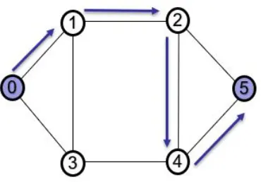
2.11 Six node network topology . . . 19
2.12 Existing communication . . . 20
2.13 Allocation of new resources . . . 20
2.14 Six node network topology for SDM . . . 21
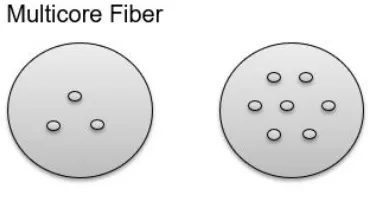
2.15 Multiple core division in SDM . . . 22
2.16 Single mode fiber . . . 22
2.17 Multi core fiber . . . 23
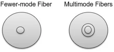
2.18 Fewer-mode and Multi-mode fiber . . . 24
2.19 Models used in SDM . . . 26
2.20 Six node network topology showing optical reach . . . 27
2.21 Modulation format chart . . . 28
3.1 Six node network topology with a virtual node at 0 . . . 38
3.2 A six node network topology with data centers . . . 39
3.3 Available spectrum . . . 40
3.4 Bandwidth allocation on available spectrum . . . 40
3.5 Bandwidth allocation on cores of available spectrum . . . 41
3.6 Gaps . . . 41
4.1 Flow diagram for experimental setup . . . 58
4.2 Topology 11-Node: 24 links . . . 62
4.3 Topology 14-Node: 21 links . . . 62
4.4 Resource usage 11-node, 14-node network . . . 63
4.5 Blocking probability in 11-node, 14-node network . . . 64
4.6 Resource usage vs number of requests with disaster with 4 cores . . . 65
4.7 BP vs number of requests with 4 cores . . . 66
4.8 Resource usage vs number of requests with 6 cores . . . 66
4.9 BP vs number of requests with 6 cores . . . 67
4.10 Resource usage vs number of cores with 50 demands . . . 68
LIST OF SYMBOLS
Symbol Definition
BP Blocking Probability
BPSK Binary Phase Shift Keying
COST-239 European Network Topology
DC Datacenter
DCN Datacenter Network
DEMUX De-multiplexer
DWDM Dense Wavelength Division Multiplexing
FMF Fewer Mode Fiber
Gbps Giga Bytes per second
GHz Giga Hertz
ICT Information and Communication Technology
ILP Integer Linear Program
LAN Local Area Network
MCF Multi Core Fiber
MUX Multiplexer
MCF Multi Mode Fiber
NSFNET National Science Network
MUX Optical Carrier
OFDM Orthogonal Frequency Division Multiplexing
QPSK Quadrature Phase Shift Keying
QAM Quadrature Amplitude Modulation
RWA Routing and Spectrum Assignment
SMF Single Mode Fiber
SpRcs Spectral and Spatial Resources
Tbps Tera Bytes per second
TDM Time Division Multiplexing
WAN Wide Area Network
Chapter 1
INTRODUCTION
1.1
Overview
The networks in which the dominant physical layer of technology for transport is optical
fiber is known as optical networks. They can either be opaque or all-optical, or can be
single-wavelength or based on dense wavelength division multiplexing (DWDM) [2]. In
simple terms, it can be defined as a means of communication in which the electrical signal
is converted into modulated optical signals for communicating data from specified source
nodes to specified destination nodes in the network. The medium of communication is
optical fiber cables. Optical networks are considered to be dominant in the information and
communication (ICT) sector because of their all-optical approach for a wide-area network,
where the required information can be transmitted in the optical domain between nodes and
at a distance of thousands of kilometers, without any conversion to the electrical domain.
Optical fibers provide us with a higher rate of data communication, compared to copper
cables. Also, it is cheap and is more resilient towards electromagnetic interference, and
is capable of covering longer distances. We know optical fibers can provide a bandwidth
capacity of the order of Gigabytes per second (Gbps) [3]. Furthermore, a capacity from
40 Gbps to 100 Gbps per channel is now commercially available in backbone networks
in Wavelength Division Multiplexing (WDM) [3]. WDM is an optical technique where
we can combine optical signals of different wavelengths onto a single strand of the optical
fiber. This is achieved by adding multiplexer at the transmitters end and demultiplexer at
the receivers end [4]. It combined two signals at a time on a single strand of the fiber
a combination of up to 160 signals on a single strand of fiber at the same time. This
advancement in technology has helped in increasing the capacity of the network without
having to install more fibers.
The inflexible nature of WDM networks create limitations on network utilization. They
require preallocated bandwidth request for a connection, even when the data rate claimed
for the communication is not sufficient to fill the entire data carrying capacity of that
band-width. Orthogonal Frequency-Division Multiplexing (OFDM) technology has recently
come up as a promising technology for future high-speed optical transmission. The
modu-lation technique used in OFDM achieves better spectral efficiency (i.e., how much data rate
can be supported for a limited spectral bandwidth [5]) and impairment tolerance [6], it
de-livers the required capacity of bandwidth depending on the demand size. Thus, higher
bandwidth capacity with an order of Terabits per second (Tbps) can be achieved with
OFDM.
With the rapid advancement of technology, a lot of progress has been made in
find-ing innovative ways to increase the data-carryfind-ing capacity of a sfind-ingle optical fiber, hence
minimize the number of fibers used [7]. There are several possible methods for
increas-ing transmission capacity over fixed bandwidth, but most of which are already in use [8].
Hence researchers wish to explore the one remaining unused dimension, which the
spa-tial dimension. Thus, space division multiplexing (SDM) in optical networks seems to be
coming up as a promising solution with the potential to overcome the possible capacity
crunch problem in the backbone networks. In SDM, a single fiber is replaced with
mul-tiple fiber and used in parallel. This enables higher data transmission by using the same
resources simultaneously, thus saving both time and resources. Researchers have been
suc-cessful in exploring their attempt to optimize multiplexing in time, wavelength, phase, and
polarization. Nowadays commercial systems utilize all the four dimensions to send more
1.2
Motivation
Optical networks form an integral part of current communications networks, carrying
information anywhere starting from a few kilometers to miles on a transcontinental scale.
Earlier in the 1980s, when fiber technology started to substitute copper wire, the first
gen-eration systems operated at bit rates of 40 Mb/s and required support from repeaters every
10 km. But todays technologically updated networks offer 100 Gb/s per wavelength [3].
However the increase in data traffic with the growth of smart devices, video-based
appli-cations and developments shows no signs of decreasing. The first step towards solving the
capacity crunch problem is to explore the different modulation formats to obtain higher
spectral efficiency. Going any further would in theory require the use of super-channels
that include multiple sub-bands beyond the 50 GHz grid [10]. Even after so much
advance-ment, the data transfer capacity remains limited, 400 Gb/s and 1 Tb/s running on legacy
systems will be inadequate to bridge distances greater than 2,000 km in long links with
high spectral efficiency [4]. These issues lead to a maximum achievable spectral efficiency
for 2000 km for a single-mode fiber (fibers allowing a single light signal to propagate) of
less than 7 bit/s/Hz [10] - the With traffic volumes increasing by around 40 percent each
year, it hints that optical networks face a capacity crunch unless a step-up in technology
can be achieved [4]. There are many ways to increase optical transmission system capacity
over a fixed bandwidth, and most of them are already being used, including modulation
us-ing different amplitude levels, two orthogonal subcarriers (cosine and sine modulation) and
polarization [11]. Space-division multiplexing has been proposed as a solution to enhance
1.3
Problem Statement & Solution Outline
Earlier Wavelength Division Multiplexing has been used for nearly a decade to come
with communication schemes when one or more components failed in traditional networks
when a disaster occurs. But with the advent of cloud computing, people now can access
similar applications through the Internet irrespective of their physical locations. Cloud can
be said to be a virtual data repository. It refers to accessing computer, information
technol-ogy (IT), and software applications through a network connection, often by accessing data
centers using wide area networking (WAN) or Internet connectivity [13]. Cloud computing
increases productivity, helps increase cash flow and contributes to many more benefits such
as flexibility, disaster recovery, security and likewise. Hence we can say technology has
almost migrated to clouds now. With this it has become necessary to maintain all the data
in the cloud somewhere, so that it is accessible to anyone anywhere as promised. Thus we
came up with the concept of data center (DC) which can be defined as a centralized
repos-itory which possibly maybe physical or virtual for maintenance of data [14]. Approaches
had to be modified from WDM when it started involving DCs as it takes into account
mul-tiple files stored in mulmul-tiple locations. Hence, it has drifted to Elastic optical networking
which allows each communication to dynamically adjust its resources (e.g., the optical
bandwidth and modulation format), depending on bandwidth requirements and
transmis-sion characteristics for the communication [15]. Most of the existing work on DCs focuses
on static lightpath allocation where the lightpath are setup before the network starts
oper-ating. However presently it is expected that lightpaths should be created on user demand
and resources should be restored after the communication is over, so that we can reuse the
same resources for a different communication now. In our thesis we extend this approach
to SDM where we allocate bandwidths for subcarriers or contiguous optical carriers (OCs),
a fiber instead of lightpaths [15]. We consider a dynamic scenarios where, in response to
each request for communication, the corresponding communication scheme is determined.
Also, our approach takes data replication into account as a DC network must store multiple
copies of each file in the network, so that at least one copy of each file is guaranteed to
be available to handle any request for that file, even after a disaster happens. Not much
progress has been made in this field earlier.
1.4
Scope of thesis
In the optical networking group, Dr. Al Mamoori has been investigating problems on
SDM for DC networks. She has proposed an Integer linear programming (ILP) as well
as a heuristic method to solve the resilient SDM data center network design problem for
dynamic traffic [16]. In her thesis, she presented her experiments in for the heuristic
ap-proach but the performance of the optimal solution has not been studied yet. In this thesis,
we would focus on the optimal results and also study the performance comparison with the
heuristic approach.
1.5
Structure of thesis
The remaining thesis is organized as follows. In Chapter 2, we have reviewed basic
concepts of optical networks based on SDM, the notion of disaster resilient techniques and
data center networks. The algorithm for the data center network design is given in the
form of an Integer Linear Program in the thesis of Dr. Al Mamoori. We have presented
our proposed approach in Chapter 3. In order to make this thesis self contained, a detailed
explanation of the ILP formulation is also given in Chapter 3. Chapter 4 is the primary
contribution of this thesis and describes the implementation details of our approach, the
Chapter 2
REVIEW OF RELATED TOPICS
2.1
Fundamentals of Optical Networks
Over the past score of years, networks are known to have evolved from being relatively
static, having fairly homogeneous traffic to being more configurable and carrying a
het-erogeneous number of services. Computer communication had started with copper wires
as the medium that carry electrical signals, encoding the data to be transmitted from one
device to another. Copper had many limitations as a medium of communication (e.g., most
of the energy used to get wasted in the form of heat [12]). The tremendous increase in
the need to communicate large volumes of data over the years increased the need of high
speed networks with huge bandwidth. In the last two decades, enormous advancements
have been made for using alternative media for communication. Hence, an optical network
can be defined as a technological arrangement of signals that connects more than a single
computer or any other devices which can generate or store data in electronic format using
optical fibers [12]. It consists of a number of nodes which are interconnected using
opti-cal fibers and possesses the ability to carry out communication across the network using
optical signals. It can be used for both local area networks as well as wide area networks.
It can carry large amounts of data at high speed and over long distances. Not only does it
provide a higher capacity but is also cost effective, hence can be efficiently used for new
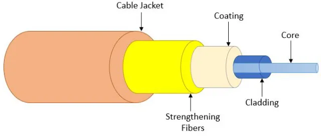
Figure 2.1: Optical Cable
2.1.1 Components of Optical fiber
An optical fiber is made of five parts.
• Core - The first layer in the fiber is the core. It is made up of silica. [12]
• Cladding - The second layer is the protective sheath, it is called cladding. It
helps in prevention of data loss as it increases the cores total internal reflection
[17].
• Plastic Coating - A plastic coat is wrapped around the fiber to reinforce the
core and cladding for the third layer [17].
• Strengthening fibers - For added support, the fourth layer of the fiber cable is
made of strengthening fibers.
• Cable jacket - Lastly the outer layer of the fiber is wrapped in a cable jacket
to protect against elements [17]. The cladding has a lower refractive index,
compared to the core, to keep the light signals inside the core [17]. Optical
signals travel down a fiber-optic cable by bouncing repeatedly off the
bound-ary between core and cladding. When an optical signal hits glass at an angle
less than the critical angle [18], it reflects back in again due to total internal
transmit light or data quickly over long distances.
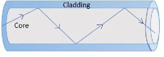
2.1.2 Total Internal Reflection
Total internal reflection occurs when a propagating light wave strikes a surface or a
medium at an angle which is larger than a particular critical angle with respect to the normal
to the surface. The index of refraction of an optical material or glass is a measure of the
speed of the light in the material, and any change in this index of refraction causes light
to bend [18]. Refraction causes light to be reflected from the surface after a certain angle;
hence this reflection is used by the optical fiber to trap light in the core of the fiber, which
has a proper index of refraction.
Figure 2.2: Total Internal Reflection
2.2
Cloud Computing
With significant advancements in Information and Communications Technology (ICT)
over the last half-century, our generation seems to have migrated to cloud computing.
are commoditized and delivered like traditional utilities such as water, electricity, gas, and
telephony [18]. Clouds are nothing but remotely hosted servers on the Internet. We can
ac-cess any resource or data irrespective of location, time or device if at all we are connected
to the Internet [19]. It is a high capacity Internet-based computing which requires large
data centers to store data. Cloud computing is a techno-scientifically distributed computing
model; it differs from a traditional one as 1) it is largely scalable, 2) it can be encapsulated
as an abstract entity that delivers various levels of services to customers outside the Cloud,
3) it is driven by markets of scale [44], and 4) the services can be dynamically configured
(via virtualization or other approaches) and delivered on demand. Lately, industry leaders,
research institutes, also Government are up to adopting Cloud Computing to solve their
ever increasing computing and storage problems arising in the Internet Age [20].
2.3
Data Center
Presently, it is standard practice to reach content across the Internet autonomously
with-out reference to the underlying hosting infrastructure of the Internet. This foundation
consists of data centers that are observed, controlled and maintained around the clock by
content providers. Providers such as IBM, Amazon, Microsoft, Google, Salesforce, have
started to establish new data centers for hosting Cloud computing applications in several
lo-cations across the world to provide redundancy and secure reliability in case of disasters or
site failures. A data center serves as a central computing/data storage resource to handle an
organizations equipment, data resources, IT operations, storage and distribution of its data.
Data centers house a networks most critical systems and are essential to the continuation of
daily actions. Hence, the security and reliability of data centers and their information are
of a prime priority to organizations [21].
The information we access over the Internet or say information we share over Internet,
are stored somewhere in the cloud. Organizations use data centers for the same purpose.
Along with that, IT operations can be characterized as a crucial aspect in most
organi-zational procedures around the world. Business continuity of a company relies on their
respective information system department to run their operations [1]. To save a company’s
operations from catastrophic failure, it is necessary to provide a reliable IT infrastructure.
Also, information security of a company is one their important concern, hence a data center
also has to offer a safe environment which minimizes the chances of a security breach [1].
Figure 2.3: Data Center Server [1]
2.4
Disaster
Any accident or a natural catastrophe which causes major damage or interrupts the
nor-mal flow of activities is called a disaster. It may occur over a snor-mall area or can spread over
a relatively larger area. In the context of optical networks, we might want to describe it
as any natural or man-made phenomenon which disrupts the data flow in an information
earth moving operations are disasters to be anticipated.
2.4.1 Types of failures during a disaster
• Link Failure- A single link goes down at a time (fiber cut)
Figure 2.4: Link failure between node 2 and node 5
• Node Failure- All links to/from node go down simultaneously.
2.5
Faults in Optical Network
The Internet has become associated with all aspects of modern life, and the significance
of a network interruption is considered a serious problem. It is observed that the Internet is
not sufficiently resilient and survivable, and thus significant research is in progress to
im-prove the situation. The objective of setting up a resilient network is to decrease the
proba-bility of a fault occurrence which might lead to failure in communicating data. This may be
done by reducing the impact of an adverse event on network services. These defenses can
be identified by developing and analyzing the threats. Therefore, the main techniques for
designing disaster-resilient optical networks are to provide geographically diverse multiple
paths for communication, so that the network can continue communication avoiding the
parts of the network affected by a disaster. The next criterion for successfully designing a
disaster-resilient optical network is to detect an adverse event or condition when it occurs.
In this regard, the individual components such as routers can detect disasters and can
de-termine when and where the defense mechanisms have failed. There are different ways to
determine if there is a fault in the network. In the case of a disaster, an alternate path, called
the backup path, can be used to overcome the effects of the disaster.
2.6
File Replication
The concept of saving multiple copies of files at various data centers in a cloud is called
file replication. It is typically measured in Recovery Time Objective (RTO) and Recovery
Point Objective (RPO). There might be various reasons why we might need to have replicas
of the files in the data center. As example, there might occur a scenario where the shortest
such scenarios we might want to fetch the data from the nearest data center. Other relevant
reason can be the occurrence of a disaster (e.g., an earthquake or a landslide). To recover
from a disaster, our primary responsibility is to restore the technological environment back
to an operational level within a designated time frame [22]. This time frame is generally
pre-determined by the requirements of the company or the institute [22]. Data loss depends
on the time it takes to restore and reestablish the operational environment [22]. Earlier data
replication was done by keeping a copy or backup of the data to remote sites. Whereas,
data replication now refers more to almost immediately accessible data stored in multiple
locations over the cloud. For large scale replication, it is mainly done for cloud based
systems using data centers. [22].
• Replication strategy when a file f is requested in a fault free network:
Figure 2.6: Communication in fault free network
There are multiple paths a route may select for successful data transmission. If
we consider the above network topology in (Fig. 2.6), we see that there more
than one paths are available, when data is requested from node 5 (just showing
• Replication strategy when a file f is requested in a network affected by a dis-aster:
Figure 2.7: All the links connected to node 3 fails
If we consider the above network in (Fig. 2.7), when node 5 requests the file
f, it was previously fetched from data center 3. But now if node 3 is affected by a disaster, a backup path from a new data center (which has a copy of file f) may be used.
2.7
Optical OFDM
The ever-increasing growth in data traffic requires more efficient and robust transmission
methodology for data communication at more than 100 Gbps. Hence, it becomes necessary
to reduce the total bandwidth requirement for data transmission. To achieve that
investiga-tors have investigated some technology other than WDM. Orthogonal Frequency-Division
Multiplexing (OFDM) has appeared as a promising alternative to WDM. The main reason
al-lotted exactly as much bandwidth he/she requires. OFDM-based spectrum-sliced elastic
optical path network (SLICE) has higher spectrum efficiency compared to WDM because
of the granularity of the sub-carrier frequencies. OFDM works for communication
re-quests, which requires a larger bandwidth due to its elastic bandwidth allocation property
and possess a better spectral efficiency and impairment tolerance [4]. In this technique, the
spectrum on a fiber is split into a number of small bandwidths called the subcarriers. Each
bandwidth is maintained by a modulated subcarrier. Each subcarrier carries a relatively low
data rate signal that modulates the signal [23]. The number of subcarriers gets allocated
according to the request. More than one contiguous subcarriers gets allocated when a
con-nection demands a capacity larger than a single OFDM subcarrier. In this way, only the part
of the available bandwidth on each fiber is used, as opposed to the WDM technique. Unlike
in WDM technology, where fixed spacing is ensured between two carrier wavelengths to
avoid interference within two signals, in OFDM technology, subcarriers overlap with one
another. Due to the orthogonality principle of OFDM, the signals do not interfere with each
other.
Figure 2.9: Spectrum of OFDM
2.8
Orthogonality Principle in OFDM
We see that in OFDM technology, subcarriers overlap with each other. The information
on a specific subcarrier, however, does not get overlapped up with the other subcarrier,
even though these subcarriers are overlapping. As shown in the figure 5 when a subcarrier
is considered at its peak, other subcarriers have zero crossing at that particular point. Thus,
information is only being read when the subcarrier is at its peak level. This certainly avoids
the interference of two signals. The use of orthogonal subcarriers allows usage of more
subcarriers per bandwidth which in turn increases the spectral efficiency.
2.9
Routing and Spectrum Allocation
For a given network topology, a route and a spectrum has to be allocated to each
com-munication request which include a source for the comcom-munication, the destination for the
communication and, on each fiber in the path, an unallocated bandwidth sufficient to
ac-commodate the required number of subcarriers for the communication. This process of
determining the route and the spectrum for the communication request is known as the
Routing and Spectrum allocation (RSA). The main purpose of RSA is to efficiently find
an appropriate path and assign a spectrum for the communication request, such that no
two requests are allotted the same bandwidth where one or more edges are being shared.
Also, each communication request should maintain the same bandwidth. The objective of
RSA is to maximize the number of connections on the network by minimizing the usage of
frequency spectrum. RSA mainly consists of three constraints:
• Spectrum Continuity Constraint: According to this constraint, the spectrum
assigned to each lightpath must be the same throughout the route. Thus the
starting frequency/bandwidth should be same for each request from the source
to the destination on all the fibers to be used in the lightpath.
• Spectrum Clash Constraint: This constraint indicates that any two lightpaths
that share a common optical fiber must be allocated with non-overlapping
spec-trum or bandwidth that is separated by at least one guard band.
• Spectrum Contiguity Constraint: This constraint assures that the subcarriers
2.9.1 Spectrum Allocation in OFDM Networks
• Static Spectrum Allocation: In this method of allocation the communication
requests are known in advance. Once the connection is set up, it continues for a
long time. It is not concerned about any request that is made after the network
is deployed and spectral resources, once allotted, are never freed up.
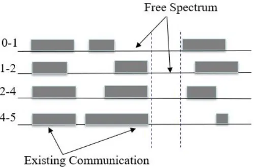
• Dynamic Spectrum Allocation: In this method of allocation, new route
se-lection and bandwidth allocation takes place in response to the user requests as
they are received by the system. Once a communication is over, resources used
for the communication are no more reserved, that is, they are freed up, so that
it can be utilized for other requests.
Figure 2.12: Existing communication
Figure 2.13: Allocation of new resources
2.10
Space Division Multiplexing
Common techniques used in optical communication are Wavelength-division
multiplex-ing (WDM), Time-division multiplexmultiplex-ing (TDM), Polarization-division multiplexmultiplex-ing (PDM)
but these have almost reached their scalability limits now. In order to satisfy the
exponen-tial growth of data traffic, optical networks have come up with the strategy of
exploit-ing one remainexploit-ing unused dimension, which is space. Increasexploit-ing popularity and variety
of bandwidth-demanding applications lead to incremental exhaustion of available spectral
appeared as an up-and-coming technology for overcoming bandwidth limitations.Space
Division Multiplexing (SDM) technology has attracted a lot of attention due to its superior
advantages for optical communication. One of them being it’s greater data transmission
ca-pacity as it can transfer larger quantity of information through a single optical fiber making
it both cost and time effective [25]. The difference from other ways of multiplexing and
in SDM is that, a single fiber is replaced with multiple fibers and is used in parallel data
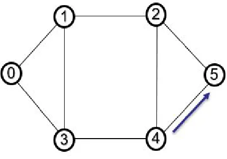
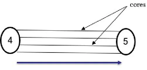
transmission. As an example in the topology below, we have considered data to be flowing
from node 4 to 5, earlier we considered bidirectional edges for data flow, but now in SDM
multiple cores (four cores as shown in figure 2.15) are used to carry data from the source
(node 4) to the destination (node 5). This enables larger data transmission using the same
resource simultaneously.
Figure 2.15: One super-channel id divided into multiple cores in SDM
2.10.1 Types of Fibers used in SDM
SDM supports parallel transmission of optical signals propagating simultaneously for a
communication request. Numerous technologies have been introduced for SDM, as
fol-lows:
• Single Mode Fiber: Single Mode fiber optic cable the diametrical core is
rel-atively small. It allows only a single mode of light to propagate. Hence, as
the light passes through the core, the number of light reflections gets limited,
lowering the attenuation and creating the ability for the signal to travel further.
We can thus use SMF for long distance data transmission [26].
• Multi Core Fiber: This involves multiple single mode cores bundled in the
same cladding. one-ring, linear-array, two-pitched, dual-ring, and hexagonal
close-packed structure are examples of few types of core placement structures
which has been proposed. One disadvantage of using MCF is that since
multi-ple cores are bundled together, signal impairments might occur due to crosstalk
between adjacent cores whenever signals are transmitted [9].
Figure 2.17: Multi core fiber
• Multi mode or Few-Mode Fiber (MMF/FMF):We find that multi mode fiber
optic cable has a relatively larger diametrical core which allows multiple modes
of optical signals to propagate. Due to this, the number of light reflections
created increases as the light passes through the core, thus allowing more data
to pass through simultaneously. But the quality of the signal is reduced over
long distances because of the high attenuation and dispersion rate with this
type of fiber. These fibers can be used for short distance, data transmission or
Figure 2.18: Fewer-mode and Multi-mode fiber
2.10.2 Ways of realizing SDM Transmission
SDM allows multi-carrier data transmission. Communication in SDM uses high-capacity
super-channels consisting of multiple optical carriers on multiple fibers (in multi-fiber
SDM) or multi-mode fibers. Each super-channel carries signals of a specific modulation
format and carries a part of the data traffic. In SDM, the optical carriers can be transmitted
using both spectral and spatial resources (SpRcs). Hence the super-channels can be formed
in both frequency and spatial domain using the best resources. There are a few models
which differ in the grade of spectral and spatial flexibility and are used in various scenarios
of data transmission [9].
• Fixed-grid/Single - It is similar to WDM network with an expansion in the
spa-tial domain. In this type of model, the spectrum is divided into fixed frequency
grids, and single-carrier transmission is utilized.
• Flex-grid/Single An additional flexibility is introduced in the spectral domain
by means of a flexible grid. The optical carriers can now occupy flexibly
allo-cated segments of spectrum which might vary to suit the user requests [9].
• Flex-grid/Fixed - In this model, the super-channels are extended in the spatial
domain. Here, within the same spectrum segment, the OCs belonging to a
model is that the super-channels cannot overlap in the spectrum domain. The
spectrum is split into fixed grids where the OCs can be flexibly allocated the
spectrum requested by the user. The same bandwidth allocation throughout
the channels should be maintained in this case. This model is mainly used in
MMF/FMF systems [9].
• Flex-grid/Semi-flexible - In this model, the super-channels are further extended
in the spatial domain by introduction of spatial groups. Here, SpRcs are divided
into some groups and only one super-channel can be carried through each group
within given spectrum window [9].
• Flex-grid/Flexible - In this model, full spectral and spatial flexibility in forming
super-channels is considered. [9]. Although this scenario enables best resource
utilization theoretically, it may lead to fragmentation of spectrum that is
resid-ual of unused gaps instead of fixed spacing which is generally not considered
for allocation of new requests. Therefore, implementation of this model is
defi-nitely possible but also is challenging from the perspective of efficient demand
Figure 2.19: Models used in SDM [9]
2.11
Optical Reach
When an optical signal travels over long distances through optical fibers, the quality of
the optical signal starts degrading after it has progressed a certain distance. Hence we can
define optical reach as the distance an optical signal can travel before the quality of the
light signal degrades to such a level that it becomes necessary to regenerate it. Various
signal, amplification of the signal, it’s launched power, etc. The longer the optical reach
of a signal, the less regeneration it requires over the network, hence serving the purpose of
using less equipment thus lowering operating costs [27]. However, expensive equipment,
such as transponders and amplifiers are required for achieving longer optical reach [27].
In (Fig. 2.20), if we a consider a light path from node 0 to node 5, the length/optical
reach of the light path is 1700 kms.
Figure 2.20:
2.12
Modulation Format
Optical fiber provides higher bit rate in long-distance transmission [28]. This can be
fur-ther improved if we utilize the advanced modulation formats. Optical-fiber networks can
transmit the Tb/s bits over few thousands of kilometers. It has been observed that an
op-tical fiber networking system can have an attenuation coefficient 0.2db/km for many T Hz
of bandwidth, exceeding the transmission distance than 10,000km and holding a capacity
of more than 10Tb/s [29]. Advanced modulation formats also improve the channel
modulation formats. One of the reasons why using flex-grid is advantageous is its
distance-adaptive nature. In flex-grid networks, the modulation format for each connection can be
selected individually during the process of allocation. Distance-adaptive concepts add a
new trade-off between optical reach and spectral efficiency. For example, modulations like
BPSK do have a long optical reach, but at a cost of a low spectral efficiency. QPSK provides
better spectral efficiency than BPSK. Again, other modulations like 16-QAM transmit the
same bit rate occupying almost approximately one-fourth of the bandwidth of BPSK, but
with a significant shorter optical reach.
From the above topology in (Fig. 2.20) where the length of the path is 1700 km, we
see from the modulation format table that 8-QAM is the best suitable format which can be
applied to the network.
2.13
Literature Review
Krzysztof Walkowiak et al. in [9] discusses integer linear programming(ILP)
optimiza-tion models for SDM optical networks. The proposed models exhibit different ways of data
transmission through SDM, each characterized by different flexibility in the use of spatial
and spectral resources. They have also analyzed the details of the ILP models describing
the technological aspects of SDM. Their work is concerned with generic ILP formulations
that can be used to model various versions of SDM which can lead to the discovery of
dif-ferent ways of using the spatial domain available in SDM networks. The author describes
the types of fibers we can use in SDM networks for parallel transmission of optical signals
and briefly discusses the concept of super-channels. When a high-capacity super-channel
is transmitted over the network, it might consist of some optical carriers (OCs), which get
generated or terminated using devices called transceiver, using a particular modulation
for-mat and carrying a portion of the flowing traffic. The OCs in SDM can be transmitted using
both spectral and spatial resources (SpRcs). Authors have focused on channel based
mod-eling in this paper and described a few models through which SDM transmission can be
realized, namely Fixed-grid single, Flex-grid single, Flex-grid fixed, Flex-grid semi
flexi-ble, Flex-grid/flexible. They further formulate three ILP models and apply it to three SDM
scenarios, the first being Flex grid/Flexible. The main objective was to minimize the
over-all spectrum usage of the network to provision the demands, considering over-all the links and
SpRcs. The next considered model uses a Flex grid/Single scenario when each request is
designated to at most one SpRc on each link. Although the solution estimated by solving
this model satisfied all the constraints, it failed to address one major issue introduced by
SDM, i.e., Light path-to-Spatial-Resource (LtoSR) assignment. The last model discusses
single entity while having the freedom of switching spectral slices freely. They compared
the optimal solution given by the thee ILP models and concluded that the first two did not
seem to be scalable when solved directly using exact methods, so they might as well come
up with a heuristic solution of it in future.
The paper [30] concentrates on a distance-adaptive scenario when the same connection
request can be transmitted with different modulation formats and is associated with
differ-ent spectral efficiencies and optical reaches. As spectrum fragmdiffer-entation degrades the
per-formance (in terms of blocking probability), in flex-grid networks the modulation format
can be decided independently for each connection during the resource allocation process.
For example, modulations like BPSK, have longer optical reach, but have low spectral
ef-ficiency, whereas 16-QAM transmits same data using one-fourth of the bandwidth. The
paper focuses on the allocation of dynamic connection requests when they are received,
deciding its route, modulation, and the band to be allotted through Routing and Spectrum
Assignment (RSA). Zaragoza et al. reviews existing RSA proposals in the paper which
ap-ply to heterogeneous flex-grid networks, evaluating their blocking performance averaged
among services, their fairness in balancing the blocking probabilities observed by different
services. Simulation study has been performed to analyze the performance of two different
RSA algorithms namely blocking model and incremental model. The authors also propose
Partial-Sharing-Partitioning (PSP), that finds a compromise between network capacity and
fairness. The Partial-Sharing-Partitioning (PSP) scheme manages the spectrum in
hetero-geneous flex-grid network. When a request is sent, the PSP controller allocates it into the
dedicated partition for service. If infeasible, it tries to allocate it into the shared partition.
The request gets blocked if it fails to do so. In the paper, the authors compare the network
capacity and fairness performances for a set of previously proposed algorithms,
reveal-ing their merits in both dimensions. Results show that PSP algorithm performs better for
In the paper [31] Muhammad et al. discusses that for encompassing the capacity
limi-tation of the networks based on single-core optical fiber (SCF) and for attaining far higher
transmission throughput and spectral efficiency, research community researchers have come
up with the idea of exploiting the only remaining unused dimension, i.e., space. For
assign-ing of spectrum slices by the traffic demands in flex-grid networks, the well-known routassign-ing
and wavelength assignment (RWA) problem is modified to the routing and spectrum
al-location (RSA) problem. The flex-grid networks use multi-core fibers for spectrum and
core allocation during traffic demands. Due to the spectrum non-overlapping constraint in
flex-grid different traffic demands with common spectrum slices cannot traverse through
the same network link. Although, demands can be routed through the same link but
dif-ferent cores if they share some common spectrum slices [31]. The paper also investigates
the routing, spectrum and core allocation (RSCA) problem for flex-grid optical networks
formulates RSCA network planning problem using ILP. For a RSCA problem, all the traffic
demands in the network are known before i.e the requests are not dynamic. The authors
give an optimal solution for provisioning the demands through proper allocation of
spec-trum and core, while efficiently utilizing all the specspec-trum resources. The optimal solution
evaluates the number of spectrum slices required to serve a given traffic demand, and also
fulfill all the other constraints, such as inter-core crosstalk and spectrum overlapping
simul-taneously [31]. The paper gives a brief sketch of the crosstalk issue for networks with MCF.
To incorporate the inter-core crosstalk in the ILP formulation two different approaches were
proposed. First, slices with same spectrum cannot be assigned to different demands that
transmit through neighboring cores unless the crosstalk level at the receiver end is beneath a
given threshold. The other approach is to pre-compute the crosstalk values for all the paths
and choose a route with the value of crosstalk below a given threshold [31]. A scalable
and effective heuristic is proposed for the same problem. After observing the solutions,
but bigger topologies with high traffic demands efficient solutions within optimal time can
be obtained if heuristic algorithms are used. The applied heuristic strategy distributes the
traffic demands according to the required spectrum and path. To establish a new request,
the spectrum resources are gradually increased after every iteration until the demands are
met in the network. The results conclude that the proposed heuristic can generate a solution
which might be close to optimal solution in polynomial time [31].
The paper [15] gives an overview of the latest developments and possible approaches
concerning flexible optical networking and the observed advantages that spatially
flexi-ble networking approaches can contribute to optical networks. It refers to the capacity of
a network to dynamically adjust its resources, such as the modulation format, or optical
bandwidth according to the required bandwidth and transmission characteristics of each
requested connection. Klonidis et al. discusses the different channel allocation options
over the available fiber dimensions which are its wavelength, bandwidth or space approved
by the latest relevant technology advances and research efforts. Next, the possible
flex-ible networking approaches considering both spectral and spatial network flexibility are
commented on and discussed, identifying their benefits, limitations, and synergies [15].
The author says that the pure SDM approach of placing a spatial demultiplexer is prior to
a spectral demultiplexer to process and extract the spatially multiplexed data can also be
applied to the spectrally flexible networking systems. The last part focuses on network
de-sign, planning, operation, and control issues, addressing the latest advancements in flexible
optical networking, while also highlighting the primary research directions and required
modifications for the introduction of flexibility in the space dimension [15].
Wang et al. in [32] discusses that the Orthogonal Frequency Division Multiplexing
(OFDM) technology enables the elastic and flexible bandwidth allocation in the SLICE
network [33]. When a user request requires multiple sub-carriers, consecutive sub-carriers
guard-band frequencies [32]. Similar to RWA in WDM networks, the SLICE network
de-ploys the routing and spectrum allocation (RSA) process to serve the traffic demands [32].
The objective of the paper [32] is to study an optimal solution and also propose new
ap-proaches for the analysis of the number of subcarriers used in a general mesh network. The
authors present Integer Linear Programming (ILP) formulations for optimal RSA with two
optimizations goals. The first being, minimizing the maximum subcarrier index among
all the fibers, and the second being the minimization of the total allocated sub-carriers
over all the fibers, keeping five constraints in mind, namely, the traffic demand constraint
and Sub-carrier capacity constraint, Spectrum Continuity Constraint, Guard-Carrier
Con-straint, Sub-carrier Consecutiveness Constraint [32]. They also analyze the upper and lower
bounds for the maximum subcarrier index in a SLICE network. These methods improve
the bounds for the case with predetermined routing knowledge. Moreover, the simulations
presented in [33] review two other efficient heuristic algorithms, namely the BLSA or the
balanced load spectrum allocation and SPSR or the shortest path with maximum spectrum
Chapter 3
OPTIMAL RSA FOR SDM OPTICAL NETWORK
UNDER DYNAMIC TRAFFIC
This chapter gives a brief overview of the optimum algorithm for handling a request for
communication in a data center network using SDM. As explained in the introduction, the
algorithm presented here appears in [16] and is given here for completeness.
• Introduction to the problem.
• Aim of our problem.
• Assumptions made.
• Idea of Virtual Node.
• Concept of Gaps.
• An ILP Formulation to solve the problem.
• Justification of the ILP.
3.1
Introduction to the problem
A network consists of nodes (representing source and destinations of data, typically
com-puters or data centers) and edges (representing fibers in the network). A cloud is a network
of data centers which handles customer requests irrespective of the location of the user.
The problem is to process a request for a file determine a strategy for robust data
communicated to the node requesting the file even if a disaster (such as an earthquake or
fire) occurs. For maintaining a robust DC network, it must be ensured that the network
stores multiple copies of each file in different nodes of the network, so that at least one
copy of each file is available even after a disaster happens, ensuring no interruption of
services. In our investigation we are considering the dynamic scenario where a specific
communication scheme is determined in response to each request for communication. If
we consider a network of n nodes and e bidirectional edges, and set of disasters D, our replication strategy must ensure that, for all the disaster scenarios whered∈D, and for all the communication requests possible, it is possible to determine a fault-free path to enable
communication. The replication strategy in [16] determines how many copies of a file, (say
mcopies ) is required as well how many data centers (S1j,Si2, ..,Smi ) should have a copy of the file fi[16]. We determine the route for communication both primary communication as well as backup communication when a primary path is affected by any disaster using an
in-teger linear program. In other words, the problem we are considering is to handle a request
for a file fifrom a nodet. We assume that, before the network is deployed, the replication strategy that file fiis saved at nodes, say,Sij, 1≤ j≤mhas been already determined. The problem is as follows:
For a fault free network :
The communication strategy has to ensure that, for file fi, it is possible to have a possible path, also called theprimary pathfrom some nodeSij tot which may be used for commu-nication using SDM. As we also intend to minimize the resources used, here we consider
three modulation formats along with their respective spectral efficiencies. We also take
into account the fact that if a modulation format has a higher efficiency, the optical reach
is lower. Our objective is to find the shortest viable path for communication, such that
the length of the path is less than the optical reach for BPSK format. BPSK format is
QPSK (4800 km), 16QAM (2400 km) which can handle communication with lesser optical
reach [15] in a more efficient manner.
For a network affected by any disasterd∈D:
It must be possible to have a fault-free viable path, appropriate for communication using
SDM, called a backup path which avoids any disaster d that disrupts the primary path, from some nodeSki tot. Our scheme for the backup path ensures that when a primary path is disrupted by disasterd, irrespective of the disaster, it must be possible to use the same backup path for communication to nodet. Since we intend to deal with a large set of com-munication requests via a cloud connecting to DCs, spectrally and spatially flexible optical
networks are likely to be ideal candidates for ultra high speed communication needed for
data center networks. We use flex-grid fixed-SDM model for this purpose, since this is
technologically viable and yet offers great scope in terms of the choices for modulation
format, bandwidth used for communication and space multiplexing. Our proposed scheme
uses the idea of dedicated path protection to determine path for backup communication to
handle disasters.
3.2
Assumptions made
• We have already determined the replication strategy for our system so that the
locations for all the files f1,f2..fn are known. In general, each file will be replicated at several data centers, so that, if there are m copies of file fi, we know that copies of file fiare saved at data centersS1i,S2i..Smi .
• The network uses OFDM for data communication.
• The network uses flex-grid fixed model for SDM networks.
• The network is supposed to already support a number of on-going
details of each existing communication are known to us, so that, for each
on-going communication, we have all information about the scheme for fault-free
communication and the scheme to handle disasterd∀d∈D.
3.3
The Objective of our algorithm
For our algorithm, we consider the set{S1i,S21i, . . . ,Smi }as the set of data centers having copies of file fi, and the setDfor disasters that might occur, where each disaster is defined by the set of edges which are adversely affected by the disaster. Our objective is to
deter-mine paths for the primary and the backup communication to handle the new request for
communication of file fito some nodetsatisfying the following conditions:
• The primary communication will be from some node Sij,1≤ j≤m, to node
t [16].
• The backup communication will be from some nodeSli,1≤l≤m. Here j6=l, since a disaster can disrupt the sourceSij used in the primary communication. This scheme for backup communication cannot use any of the edges affected
by all disasterd∈Dthat disrupts the primary communication [16].
• The length of the path used by the primary and backup communication will
de-termine the optimum modulation format to be used by the primary and backup
communication.
• Minimize the number of subcarriers needed to carry out the new
communica-tion.
• Measure the cost of the resources needed to handle the new request by the sum
3.4
Idea of Virtual Node
Figure 3.1: Six node network topology with a virtual node at 0
When a file fi is requested for communication, the source of the communication is not specified. In other words, only file fi to be retrieved is specified. Our algorithm needs to determine which node will act as the source of the lightpath. This must be one of the nodes
Sij; 1≤ j≤m that stores a copy of the requested file fi. To help determine which data center node Sij (Sli with be the source, for the primary ( or backup) path, it is convenient to visualize a new virtual node sand some newvirtual edgesfromsas follows. For each data center Sij; 1≤ j ≤m, we visualize a single virtual edge from virtual node s to data centerSij of length 0. This virtual node vdoes not exist as a node in the network. Since all edges from this virtual node has length 0, it does not affect the optical reach constraint.
We can now use standard network flow algorithms to find a primary (backup) path from the
For example, (Fig. 3.1) below, represents a topology with 6 physical nodes numbered
1, 2, 3, 4, 5 and 6 and a virtual node is assigned the number 0. The virtual node is not a
part of the original network but is a concept to enable the use of a simple single commodity
network flow algorithm. If nodes 3 and 4 contain a copy of the file to be communicated,
Fig. 3.1 shows that virtual node 0 is connected to all the potential data center nodes (node 3
and 4 in Fig. 3.1 ) in the network which are potential sources for the communication. Our
algorithm determines the optimal path from the virtual node to the requesting node based
on factors such as the distance from the requesting node, available spectrum on each fiber
in the path. We might then get the actual path for communication simply by deleting the
virtual edge. For instance if 3 is the first node in the selected path 0→3→5→6 from node
0 o the requesting node 6, the actual path for communication is that obtained by removing
the virtual edge 0→3 in Fig. 3.1)and give the path for communication 3→5→6 in Fig.
3.1)
3.5
Concept of Gaps
Figure 3.2:
Fig. 3.2 shows a six node network with data centers at node 3 and node 4 storing file
for primary communication is 3→5→6. We are using flex-grid fixed model for SDM
networks for allocating bandwidth to the new requested communication.
Figure 3.3: Available spectrum
Fig. 3.3 shows the available spectrum on the node 3→5 and node 5→6 where the
resource allocation should take place for setting up the new communication request.
Figure 3.4: Bandwidth allocation on available spectrum
The grey rectangular boxes in Fig. 3.4 depicts the bandwidth allocation on available
spectrum on node 3→5 and node 5→6.
In SDM, a single link from the source node to destination node represents multiple cores,
and each core should have equal bandwidth allocation over the spectrum. Fig. 3.5 shows
that the node 3→5 further gets divided into multiple cores (4 here) and are now responsible
for carrying out the communication. Similarly, node 5→6 gets subdivided into four cores
for the new request. Equal bandwidth allocation of spectrum takes place in all the cores
because of the flex-grid fixed model.
3.6 shows a bundle of fibers, representing an edge i → j (edge 3→ 5 in Fig. 3.6). Selected portions of each fiber in this packet are already assigned to existing ongoing
Figure 3.5: Bandwidth allocation on cores of available spectrum
Figure 3.6: Gaps
assign the unused spectrum to the new communication requests. Fig. 3.6 shows a possible
allocation of spectrum using the flex-grid fixed-SDM model.The black boxes in the Fig.
3.6 represent spectrum which has already been assigned to some other communication. If
a new request for communication uses edgei→ j, the spectrum allotted to the new com-munication must be within the bandwidths shown in Fig. 3.6. We call these permissible
bandwidths the gaps on edge (i→ j). In the situation described in Fig. 3.6, there are 3 gaps, where gap 0 has a starting subcarriera0i j and ending subcarrier b0i j. Similarly gap 1 has a starting subcarrier asa1i j and ending subcarrierb1i j, gap 2 has a starting subcarrier as
lies within one of these 3 gaps should be allocated. In Fig. 3.6 we select gap 2 according
to the bandwidth requirement of the requested communication.
3.6
Notations used in the ILP
In this section we outline the notations used to formulate the algorithm proposed in [16].
N(E): set of end nodes (bidirectional edges) in the physical network topology.
Ed: set of bidirectional edges (i.e., links) in the network that are disrupted by disasterd.
Gi j : set of all gaps on edge(i,j)∈E.
C: set of core per fiber.
s(t): source (destination) of the new request for communication. In this problemsis the virtual node as discussed above.
B: a constant denoting the bandwidth requested, measured by the total number of subcar-riers needed for communication.
k0: a constant denoting the packing density for 16-QAM modulation format.
k1: a constant denoting the packing density for 8-QAM modulation format.
k2: a constant denoting the packing density for QPSK modulation format.
d0: a constant denoting the optical reach for 16-QAM modulation format.
d1: a constant denoting the optical reach for 8-QAM modulation format.
d2: a constant denoting the optical reach for QPSK modulation format.
agi j(bgi j): a constant for all gap g∈Gi j and edge (i,j)∈E that represents the starting (ending) subcarrier wavelength of thegthspectrum gap on edge(i,j).
`i j : a constant denoting the length of the edge(i,j)∈E.
nP: number of subcarriers needed for the primary communication.
nB: number of subcarriers needed for the backup communication.
`P: a variable denoting the length of the path used by the primary communication scheme.
`B: a variable denoting the length of the path used by the backup communication scheme.
θ(ω): an integer variable representing the starting subcarrier number of the new request
for the primary (backup) communication scheme.
φ(ψ): an integer variable representing the ending subcarrier number of the new request
for the primary (backup) communication scheme.
F0P: a binary variable with a value 1 if the primary communication uses 16-QAM format; 0 otherwise.
F1P: a binary variable with a value 1 if the primary communication uses 8-QAM format; 0 otherwise.
F2P: a binary variable with a value 1 if the primary communication uses QPSK format; 0 otherwise.
GP1 : a binary variable with a value 1 if the primary communication may use 8-QAM format; 0 otherwise.
F0B: a binary variable with a value 1 if the backup communication uses 16-QAM format; 0 otherwise.
F1B: a binary variable with a value 1 if the backup communication uses 8-QAM format; 0 otherwise.
F2B: a binary variable with a value 1 if the backup communication uses QPSK format; 0 otherwise.
GB1 : a binary variable with a value 1 if the backup communication uses 8-QAM format; 0 otherwise. This includes the possibility thatF0B=1
GB2 : a binary variable with a value 1 if the backup communication uses QPSK format; 0 otherwise. This includes the possibility thatF0B=1 orF1B=1
qd: a binary variable with a value 1 if disaster d affects the primary communication; 0 otherwise.
wdi j : a binary variable for all edge(i,j)∈E wherewdi j =1 if edge(i,j)appears in the path used to handle disasterd; 0 otherwise.
xi j(yi j): a binary variable for all edge(i,j)∈Ewherexi j =1(yi j =1)if the path used by primary (backup) communication scheme for the new request uses edge(i,j); 0 otherwise.
xgi j(ygi j): a binary variable for all gapg∈Gand edge(i,j)∈E edge wherexgi j =1 if gap
![Figure 2.3: Data Center Server [1]](https://thumb-us.123doks.com/thumbv2/123dok_us/1350235.1167904/24.612.150.498.244.475/figure-data-center-server.webp)