Design Method of Vertical Component Isolation System
Seiji K i t a m u r a ~) and M a s a k i M o r i s h i t a ~)
1)Japan Nuclear Cycle Development Institute, Japan
A B S T R A C T
A structural concept of a vertical component isolation system for fast reactors, assuming a building adopting a horizontal base isolation system, has been studied. In this concept, a reactor vessel and major primary components are suspended from a large common deck supported by isolation devices consisting of large coned disk springs. A determination method of optimal vertical isolation characteristics, case studies of vertical isolation device and plant layout are shown in this paper.
1. I N T R O D U C T I O N
Although the horizontal component of an earthquake ground motion is sufficiently reduced by base isolation with laminated rubber bearings, the vertical component is transmitted directly. If three-dimensional isolation were achieved by adding a vertical isolation system, it would substantially enhance plant economy and safety. In order to realize a three-dimensional isolation system, two types of systems can be considered. One is a three-dimensional base isolation system, and the other is a combination of base horizontal isolation and component vertical isolation. By emphasizing the following tow points, the authors chose the latter system. The first point is that excessive rocking response doses not take place in native in the latter system, because the offset between the center of gravity and the isolation support position of the support structure can be made small. The second point is that vibration characteristics of each isolation system become simple by separating the isolation direction. The authors proposed a structural concept called "common deck isolation system", in which a reactor vessel and major primary components are suspended from a large slab structure (common deck) [1]. This common deck is supported by a couple of vertical isolation devices. The followings are considered as functional requirements for the device. The heavy weight of the installation structure should be supported, and simultaneously, a longer vertical period should be attained. It has high rigidity for degrees of freedom except for vertical direction. Assumed failure modes are not catastrophic. A coned disk spring with metallic material was chosen as vertical isolation device as it satisfies these requirements. Disk springs can be stacked in various configurations. They are adjustable to the specified load and/or deflection.
To show the feasibility of the concept of the common deck isolation system, a determination method of optimum isolation characteristics (isolation frequency and damping), case studies of the isolation device and plant layout are presented in this paper.
2. O P T I M A L V E R T I C A L I S O L A T I O N C H A R A C T E R I S T I C S
2.1 Method
In the vertical isolation system, it is most important to satisfy simultaneously, the reduction in the response acceleration by lengthening the period of the dynamic response of the system and the control of the response displacement. Generally, the response acceleration decreases as the isolation frequency is lowered, while the relative displacement increases. Then, a series of parametric survey by following procedures was made to identify an appropriate range of isolation frequency and damping value necessary
SMiRT 16, Washington DC, August 2001 Paper # 1264
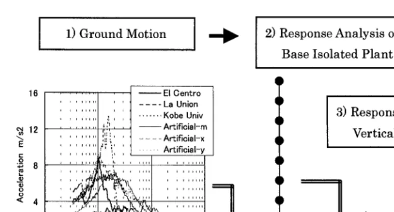
for vertical isolation. The procedure takes three steps (see Fig. 1).
1) Input earthquake motion
Since effective isolation characteristics would be obtained for various seismic waves, three kinds of observed waves and three kinds of artificial seismic waves were chosen. The response spectra of each seismic wave with 5% damping are shown in Fig. 1.
2) Vertical response of base isolated reactor building
A series of vertical response analyses for a typical base isolated reactor building was carried out, and the acceleration response time histories at the vertical isolation device level were obtained. Soil conditions are considered ranging from a soft rock site with shear wave velocity (Vs) of 700m/see to a hard rock site with Vs=2000m/sec.
3) Response analysis of vertical isolation system
Using a single degree of freedom model, a series of earthquake response analyses of vertical isolation system is carried out; and the maximum response acceleration and relative displacement were calculated. The natural frequency of the components supported by the deck is assumed to be 10Hz. As the measures representing the response of the component, the maximum value of acceleration response spectrum with 1% damping in the range of 5Hz to 12Hz was obtained.
2.2 Analysis
As analytical models for the vertical isolation system, a linear and a nonlinear model were used. At first, a series of analyses using the linear model was carried out in order to identify appropriate ranges of isolation frequency and damping value necessary for vertical isolation. The ranges of isolation frequency 0.8Hz to 2.5Hz and damping ratio 2% to 60% were examined.
Next, in order to materialize the design of the coned disk spring, a series of analyses using the nonlinear model was carried out. In the analyses, an isolation system was assumed with the combination between coned disk springs and lead dampers. The restoring force characteristics of the coned disk spring were assumed to be elastic, and that of the lead damper were assumed to be elastic-perfectly-plastic (see Fig. 2). The isolation frequency, determined by the rigidity of the linear spring, was examined in the range of 0.5Hz to 5Hz. As for characteristics of the damper, both the rigidity ratio (the ratio of the rigidity of the damping element to that of the coned disk spring) and the yield ratio (the ratio of the yield load of damping element to the support weight) were given. The ranges of rigidity ratio and yield ratio examined are 1 to 20 and 0.01 to 0.2, respectively.
To identify appropriate vertical isolation characteristics, followings were used: maximum relative displacement of 50mm, normalized acceleration of 0.75, normalized response spectrum between 5Hz to 12Hz of 0.33. Here, the upper limit of relative displacement was set based on the idea that relative displacement of the piping connected the isolation system with non-isolation system in the earthquake would be allowed to the degree equal to thermal expansion. Therefore, the input seismic wave for the analyses adjusted the input level so that the maximum velocity may become an equal value.
2.3 Optimal vertical isolation characteristics
The results of the analyses using the linear model are shown in Table 1. It was found that the appropriate isolation frequency to satisfy all the criteria ranges 0.8Hz to 1.2Hz, as far as the seismic inputs used in this study were concerned. The minimum necessary damping are 15% for 0.8Hz, are 30% for
1.2Hz.
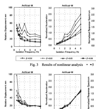
displacement, normalized acceleration, normalized response spectrum for isolation frequency. It respectively shows the case in which the rigidity ratio is made to be constant, and the case in which the yield ratio is made to be constant, Fig. 3 and Fig. 4. When the isolation frequency increases, the normalized acceleration is increased, and the relative displacement is decreased. As the rigidity ratio increases, the normalized acceleration and the relative displacement decrease, and the response spectrum increases for the contrariety. It is proven that the yield ratio shows the tendency equal to the rigidity ratio.
The result of examining the appropriate region is described. To satisfy three conditions for all the seismic inputs used in this study was only the case in which they were 0.8Hz and 1.0Hz at the isolation frequency. The range of the yield ratio and the rigidity ratio is shown in Table 2. As this result, it was proven that appropriate isolation characteristics were obtained by combining the coned disk spring with isolation frequency of 0.8Hz to 1.0Hz with the hysteretic type damper with rigidity ratio of 5 to 6 and yield ratio of 0.06 to 0.07.
3. DESIGN E X A M P L E O F I S O L A T O N D E V I C E AND P L A N T L A Y O U T
3.1 Isolation device
In order to examine whether the vertical isolation element with optimum isolation characteristics can apply to fast reactor plants, a design of the isolation element was attempted under following conditions: isolation frequency of 1.0Hz, displacement amplitude of 100mm, supported structure weight of 10,000ton. By the following procedures, the isolation element was designed. 1) Ordinary high tensile spring steels such as JIS SUP 10 and SUP 13 can be used for the coned disk. 2) Outside diameter and thickness of the coned disk are selected considering today's manufacturing performance and future feasibility from the viewpoint of machining and heat treatment. 3) Referring to a Japanese Industrial Standard (JIS) [2], the other geometries, such as inside diameter and dish free height, is determined. 4) Considering spring rate, which obtained the target frequency, and the effective deflection, number of disk springs in series is determined. 5) Considering the total length of a stack, number of disk springs in parallel is determined. 6) The following items are calculated and compared to the permissible value based on the JIS: design stress, fatigue life, relaxation of the coned disk.
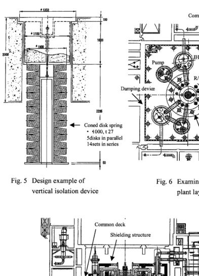
An example of the structure of the isolation device is shown in Fig. 5. In this case, the outside diameter of coned disk is 1,000mm, and the thickness is 27mm. One isolation device is constituted, stacking 5 disk springs in parallel and 14 sets in series. The unloaded height of a stack becomes about 2,200mm. Support load per one unit is 260ton, and 37 units will be placed to support the common deck.
3.2 Plant layout
An example of plant layout employing the isolation device for a first reactor plant is shown in Fig. 6 and Fig. 7. Isolation devices were mainly placed in the peripheral of the reactor vessel and in the peripheral part of the common deck. While the space for construction and maintenance was considered, the details of a weight balance, etc. is not considered. There is much room for examination of optimum configuration. Likewise, a farther examination should be done on damping devices placed in the figure in the circumference of the common deck. It was confirmed, however, that the required damping would be obtained by using about 13 lead dampers for 50tonf in the design calculation.
4. C O N C L U S I O N
isolation characteristics were examined. It was shown that effective isolation characteristics were obtained by using the coned disk spring of isolation frequency of 0.8 to 1.0Hz and the damping device with over 20% damping. The isolation device was designed, and in addition, a plant layout employing the isolation device for a first reactor plant was examined. As the result of the study, an outlook for the technical feasibility on the proposed vertical isolation system using the common deck was obtained.
The materialization of isolation device and damping device will be attempted, and the optimization of the plant layout will be examined.
References
1. Morishita M., "A conceptual study on vertical seismic isolation for fast reactor components", Proceedings of SMiRT- 13, KB09 (1995)
2. JIS B2706, "Coned disk spring", (in Japanese), 1995
: x . _
1) Ground Motion
12 E
t - O
; 8
' ' C l ~ e n r ~ r o . . . - - - - L a U n i o n , , , , , , , , , ,
. . . ,, , , K o b e U n i v
, ":: , , ~ A r t i f i c i a l - n
I ' "
. . . : : : . . . A r t i f i c i a l - x
. . .
. . . ,,i/V~' , , A~i~i~,-~
O o 0
< 4
0
0 . 0 1
2) Response Analysis of
Base Isolated Plant
7
, , , } , , , , , , , , , , ,
, e~ I )
tr' "
~
II
rl
~ r e ' " " ~ I~ . . .
l , I l l I l l I I I l I , ~i\i,l
0 . 1 1 " ~ " 1 0
Period sec
3) Response Analysis of
Vertical Isolation System
Axial Rigidity of Rubber Bearing
Soil Spring
Fig. 1 Survey for optimal isolation characteristics
P
¥
Coned disk spring
rigidity"
kO
Damping device
rigidity"
kl
yield force"
Fy
rigidity ratio •
kl/kO
yield ratio •
Fy/W
W" static weight
Fig. 2 Nonlinear restoring force
characteristics model
Table 1 Appropriate isolation
characteristics (linear model)
Frequency
Hz
0.8
Damping ratio %
lO11 1
4o10o
0 0 0
1.o
0
0
0
0
1.2
0
0
0
0
0
1.5 2.0
100
E 80 E
i
6O 40>=
y: 20
100
~
80~
eoi:5 40
y:
20ArtificiaI-M
, . . .
i
; i ; i
0 1 2 3 4 5
Isolation Frequency Hz
3.0
,- 2.5
O
~ 2 . 0 u
o ~ 1.5 "1o ._. "~1.0 O Z 0.5 0.0 ArtificiaI-M
¢
_0 1 2 3 4 5
Isolation Frequency Hz
3.0 E 3 ~ 2.5
(3. (n 2.0
¢n ¢..
~
1.5 tl) "~ 1.0E o.5
O Z 0.0 ArtificiaI-M , , _
0 1 2 3 4 5
Isolation Frequency Hz
. - - o - - B = O . 0 2 I /3=0.03 ~ .8=0.05 ,,~ ,8=0.08 ~ , 8 = 0 . 1 0
Fig. 3 Results of nonlinear analysis • "-5
ArtificiaI-M
0 1 2 3 4 5
Isolation Frequency Hz
ArtificiaI-M 3.0
2.5
'~ 2.0
~ 1.5 N
~
1.07° o.5
0.0
0 1 2 3 4 5
Isolation Frequency Hz
ArtificiaI-M
3.0 r
E
3
~- 2.5
e,J
oo 2.0 . . .
E O
1.5 . . .
n- 1.0
~
0.5 z0.0
0 1 2 3 4 5
Isolation Frequenoy Hz
I ~ Ot=l I e = 2 ~ Or=5 ,~ o t = l O " " O n ~ = 2 0
Fig. 4 Results o f nonlinear analysis • "-0.05
Table 2 Appropriate isolation characteristics (Nonlinear model)
Rigidity Ratio
Isolation Frequency = 0.8Hz
Yield Ratio B
0.04] 0.0510.0610.0710.0810.0910.10
3
4 O O O
5 O O O
6 O O O O
8 O O O O O O
10 O O O O
15 O O
50mm > Relative displacement
0.75 > Normarized accelelation
0.33 > Normarized respnse spectrum
Isolation Frequency = 1.0Hz
Yield Ratio B
0.0410.0510.0610.0710.0810.0910.10 0
0
0 0 0 0 0
0 0 0
0 0
0 0
"-111 " " i !. J ll-..r~
,'.
'~----~qO "
" - I I i IFqrq';"'"
? I II i~ :, . : I l l
i . i i1 ii . ", • "
' '> ' i ilili i ' ~,. ": 10
. ..;..;,_ ,~,,~I~L_
I .':...:
i
- - - t
~... .... ' [ ~ ! ... ..,,r
~Pu:p i
zo~ ".';.., .;..,,.,,. ,. . ,,, ... ':, , . . ' . ; -___1
..-..:. ; ~ t ~
,:":.,.'~:
~
~
.:., ~ / ~
"-.:.:
Damping device/4
!.,':;:
---N/
I
Coned disk spring
~ / ~
• t00,),t27
/ II Iil/
N~
~is~sinpar~le~ /
N ~ ! ~ _ 4
~ I ~
14 sets in se fi e s ~ ~ W
_ SO
Common deck
N
- ' ~ I ... ~ ...,
f-7:._--- i f
I s o l a t i o n
device
I_t
Fig. 5 Design example of
vertical isolation device
Fig. 6 Examination case of
plant layout (plan)
I~L
_ Ill
Common
deck
!
i
N t/
/
Shielding
structure
i ! ~ ~ ~ ~ , t l ~ g i l _' t D ' i ~ I I_L ... L ... /