Optimization of multilayer micro channels heat
sinks cooling system using genetic algorithm
Husain Zaidan
1, a *,
Robiah Ahmad
2.cand
Normah Mohd Ghazali
1b1Faculty of Mechanical Engineering, Universiti Teknologi Malaysia: 81310, Johor Bahru, Johor, Malaysia 2UTM Razak School of Engineering and Adv. Techn., Universiti Teknologi Malaysia
54100 Jalan Semarak, Kuala Lumpur, Malaysia
a[email protected], b[email protected],
Corresponding author: [email protected]
Abstract—Cooling of electronic devices is problematic by its nature simply because of the space restriction. Recent advances in high powered miniaturized electronic systems have come at the expanse of very high heat fluxes that pose challenges to thermal management research. Uncontrolled excessive heat may cause thermal fatigue and stresses and the current micro electro-mechanical cooling systems (MEMS) which utilize the single layer micro channel heat sink, introduced a decade ago, may no longer be an adequate solution. Possible extension of the layer of parallel micro channels into a stacked system, by developing two, three, and multi-layer channel systems are being investigated. The design of all these systems depends on several parameters; coolant type, channel geometry, channel dimensions, and the number of the channels. This paper reports a new model for optimizing the thermal resistance, developed based on specific parameters of the dimensions of the channel, the wall width between the channels, and using water as a coolant at 27 . The outcomes of the model were compared with other published studies. The results showed that the model is valid and reliable for further studies.
Keywords—stacked; micro channel heat sinks
(MCHS); optimization; thermal resistance; genetic algorithm; computational fluid dynamics (CFD).
I. INTRODUCTION
For reasons range from the necessity of saving power to the importance of preventing damage to electronic structures, the micro electromechanical systems (MEMS) have been rapidly developing in the last two decades. Researchers have different approaches on how to design MEMS. All designs, even with internal differences, have agreed on one important goal; namely, optimizing the performance of MEMS. One of the first pioneers in this field was a single layer micro channel with the aid of a silicon wafer (50 μm width and a 300 μm height) as the heat sink and water as a coolant which was able to handle heat flux of 790 W/cm2 at 71 K [1]. Three years later, a new micro channel has fabricated, still a single layer, but with two important differences from Tuckerman-Pease’s design: 1) air was used as a coolant and 2) dimensionless ratio of the fin and the channel thickness, / , in order to test the effectiveness of the channel width and the finding suggested that the thermal resistance was minimized at specific
channel width [2]. Away from these two early attempts, a micro channel with a square shape was constructed rather than rectangular shape that has been used until then .The 5 cm silicon square substrate has reached heat flux of 1100 W/cm2. Optimization was the core purpose of the research
network model [13]-[17]. In this study, an multilayer micro channels heat sinks (MCHS algorithms (GA) was developed to an parameters at which the performance of MC limitation and at which the multi-layer has n outcome. The approach shows that as the fl the multi-layer performance becomes null reverse optimization is taking place.
II. GENETIC ALGORITHM Genetic algorithm (GA) is a stochastic n method, inspired by process occurring evolution, which was first conceived by Previous studies have proven the increase i researchers demands for a global optimizati eliminate some of the pre-requirements of t optimization techniques. Prior works sh genetic algorithm optimization techniq successfully implemented in multi objectiv cases such as the one considered in the pro In recent years, applications of Genetic Algo thermal engineering have received much solving real-world problem. Applications o exchangers optimizations have suggested th strong ability of search and combined optim successfully optimize and predict thermal applications of GAs in the field of thermal new challenges. At this point, the ability of difference region of solution space make it p diverse set of solution. By using GAs, there variables can be optimizing at one time. model for cylindrical pin-fin heat sink algorithms as an optimization technique, Ent rate due to heat transfer and pressure drop ac minimized using genetic algorithms, they genetic algorithms is a very suitable optimiz for the optimization of pin-fin heat sinks in variables which could produce a high quality Najafi and Najafi [20], successfully utilized optimization using genetic algorithms in o optimal design parameters for plate an exchangers.
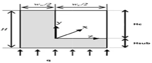
III. THERMAL RESISTANCE MO The micro channel heat sink’s thermal p effectively be described by its total therma analyse the performance of the heat sink, t described by a network of resistances conn parallel, and combination. Fig. 1 shows th multilayer micro channel in which the lo represent a single layer. The micro-channel
optimization of S) using genetic nalyse on the CHS has its own
no effect on the ow is changing, l after which a
M (GA)
numerical search in biological y Holland [18].
in designers and ion technique to the conventional howed that the que has been ves optimization oposed research. orithms (GAs) in h attention for f GAs into heat hat GAs have a mization and can
problems. Thus engineering are f GAs to search possible to find a
e are more than an optimization using genetic tropy generation cross pin-fin was y surmised that
zation technique nvolving several y solution, [19]. d multi-objective order to achieve nd frame heat
ODEL
performance can al resistance. To the modelling is nected in series, he schematic of ower part could has rectangular
cross section of height H a
w from the neighbouring c related to each other by aspe and β w /w . The heat s channels has width W , l computational zone which shown in Fig. 2. The total res channels heat sink is shown the following formula in (1)
Fig. 1. Schematic of the stacked heat sink.
Fig. 2 Schematic diagram of comput
The thermal resista modelled as shown in Fig. 3.
and width
w
and separated by channel. These parameters are ects ratios; namely, α H /wsink which is consisted of many length L and height H. The
represents a half channel is istance of the single layer micro n in Fig. 3 can be expressed by
and (2),
(1)
(2)
(multilayer) rectangular micro-channel
tational zone cross-section
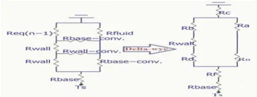
Fig. 3 Single layer heat sink thermal resistance network
The resistance network for the repeat (stacked) of "n" layers is shown in Fig. 4.
Fig. 4 Multi–layer heat sink: thermal resistance network
Since the thermal resistance network shown in Fig. 4 consists of series and pa network, the total thermal resistance of the calculated using delta-wye transformation sh
Fig. 5 delta-wye transformation
For multilayer MCHS, the fitness f equivalent resistance “ ” is expressed in
ted single layer
k for layers.
for “n”, layers arallel resistance network can be hown in Fig. 5.
function is the n (3),
In this study, the width 30cm x 30cm.The thickne channel 100 a channel 500 , both ratio / and the optimized as variables respectively with different nu the stacked micro-channel t minimized thermal resistan
0.1, 0.3,0.5, 1.0 1.5 x10
condition the model limitatio In this optimization, the utilized to optimize the total fluid used in this study is w engineering parameters for density = 997 kg/m3, speci dynamic viscosity 8.55x made of silicon with th
148 W/m .the necessary d properties required in optim Table 1.
TABLE 1.Required dimension Pr
Dimensions and proper
Heat sink length ,L (m) Heat sink width ,W (m) Microchannel height,H (m) Material thermal conductivity (Si), Coolant thermal conductivity (water Density of the coolant , (kg/m3)
Dynamic viscosity of the coolant , Flow rate, G (m3/s)
Specific heat of the coolant, J/K Number of layer
Thickness of the substrate, H (m physical and engineering parameters
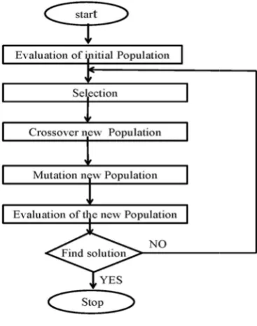
The Genetic Algorithms routine, written mostly in most important functions in data structures in the Gene chromosomes, objective fun The genetic algorithms use each step to create the nex population, selection rules parents that contribute to generation, Crossover rules children for the next genera random changes to individua flow chart of the Genetic Alg Genetic Algorithms Paramete
(3)
and the length of the sink are ess of the base of the micro and the depth of the
micro-are kept constant. The aspect spacing ratio / are
and in the simulation, umber of layers ( 1 to 5) of to investigate the effect on the
ce at different flow rate 0-6 m3/s. Bases on the above
on were defined.
genetic algorithms (GAs) were thermal resistance. The coolant water at 27 . All physical and water were taken as follow: ific heat 4179 J/Kg , and x10-4 kg/m s. The heat sink was
hermal conductivity of dimensions and thermophysical
mization process are listed in
s and properties for the optimization rocess
rties Values
3x10⁻¹
3x10⁻¹
5x10⁻⁴
(W/m ) 148
r), (W/m ) 0.613
997
kg/m s 8.55x10⁻⁴
0.1, 0.3 , 0.5, 1.0 and 1.5x10⁻⁶
Kg 4179
1-5
m) 1x10⁻⁴
s for water , 27
s Toolbooks is a collection of m-files, which implement the n genetic algorithms. The main etic Algorithms Toolbooks are nction values and fitness values. s three main types of rules at xt generation from the current select the individuals called the population at the next combine two parents to form ation and Mutation rules apply al parents to form children. The gorithms shown in Fig.6 and the
Fig.6 Flow chart Genetic Algorithms.
Table 2.Genetic Algorithm Parameter
Parameters Valu
Fitness function @multil
Number of variables 2
Population type Double v
Population size 20
Creation function unifor
Selection function Stochastic u
Crossover fraction 0.8
Crossover function scatter
IV. RESULTS AND DISCUSSI
The flow rate of 0.1, 0.3, 0.5, 1.0, an were considered to optimize the overall the [ /W] of layers 1 to 5 at constan
0.5, ⁄ 1.0, height of the cha m], and the width of the substrate optimization process was performed algorithms (GAs) of MATLAB R2012b algorithms toolbox uses MATLAB matrix fu as set of versatile tools for implementing a genetic algorithms methods..
The optimization was designed for two p the reliability of the model and to valid the of multi-layer micro channels heat sin
rs
ues
layer
vector
rm uniform
red
ION
nd 1.5x10⁻⁶ m3/s
ermal resistance, nt /
annel 500
100 m].The using genetic b .The genetic unctions to build a wide range of purposes - to test proposed model nk which was
developed in conjunction resistances connected in pa with the experimental re optimization process, the except the flow rate, . In th
Rtotal is minimized based o
model using genetic algorith resistance Rtotal, the related
number Re, pressure drop, p
dimensions of the channel ar Fig. 7shows the overa
, with the number of layers, rate of 0.10x10⁻⁶ m3/s, is t
the number of layers increa
/W or, in percentage wise its highest value at single lay 0.3x10⁻⁶ m3/s, the trend of
previous result, however th slightly higher than the it’s m3/s. The trend of decreas continues for higher flow ra of at, for instance, flow close to 100% which means to the multi-layer foundation shows that increasing the fl will decrease for and mu decrease in becomes less a The results presented here findings of the experimental results are plotted in Fig. variation of as a function o in Fig. 8 show that the high layer is decreasing as the flow
Fig. 7 Thermal Resistance with n L
Fig. 8 Flow Rate with Thermal
with the method network of arallel, series and combination esults by [12]. During the
parameters are kept constant his study, the thermal resistance on the proposed mathematical hm. With the optimized thermal
parameters such as Reynolds’s pumping rate, geometrical and re also evaluated.
all optimized thermal resistance, , 1 to 5. At the lowest flow the highest; about 2.5 /W. As ases, decreases to about 0.7 e, it decreases to about 28% of yer. As the flow rate increase to f decreasing is same as in he percentage decrease in is
s percentage of 0.10x10⁻⁶
sing with increasing layers ates but the percentage decrease
rate of 1.50x10⁻⁶ m3/s is very that there is virtually no effect n for the heat sink. “Fig. 8”also ow from 0.10 to 1.5x10⁻⁶ m3/s
ulti-layer MCHS; however the as the number of layer increases. e are in agreement with the
work performed by [12]. These 8, which clearly shows the of number of layers. The results hest for the same number of w rate increases.
Layers
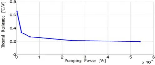
In another simulation study, the relat overall optimized thermal resistance, , /W power, , 10-4 W are conducted. It is impor
the pumping power is the power required to sink with specific flow. Fig. 9, shows pumping power, , increases, rapidly becomes almost constant as the reaches t of 0.2 /W. These results are in a experimental study in [12].
Fig. 9 Variation of pumping power with overall
optimized for stacked layer heat sinks.
The optimization goes further to show h optimized resistance, , behaves with the flo 10’’, shows that as decreases from abou 0.2 /W, the flow rate increases from 0.1 t This trend is in agreement with results by Pease’s [1] and Lei [12].
Fig. 10 Flow Rate with Thermal Resistance
Figs 9 and 10 show similarity for t between the flow rate and the pumping po resistance which are is positively related.
To complete the cycle, it is also importa the relationship of Reynolds’ number, Re factor, , and Fig. 11 shows that as Re incre 10 to 160, both laminar, the flow velocity inc
tionship of the W and pumping rtant to note that provide the heat that the as the
decreases and the lowest value agreement with
thermal resistance
how the overall ow rate, Fig. ut 0.7 /W to to 1.5x10⁶ m3/s.
Tuckerman and
the relationship ower to thermal ant to study on , and friction eases from about creases since the
density of water, , the diam of the channel, , and t constants. When the veloci power and pressure loss is ex
Fig. 11 Reynolds’ number Re with f
V. CON
The proposed model for with the results proposed by results are in agreement with by Lei, [12] on the overall o how the number of layers structure such as the flow pressure drop. The results determined at specific contro parameters such as the ratios the multi-layer micro channe alternative to the traditional high power – the factor that heat sink which is presen developed where the o approaching zero through negligible. We have show algorithms (GAs) optimizat good solutions for optimum t introductory and it is aime parameters included in the m However, more studies are the best parameters which depict the need to fulfil so facing today’s engineers and
Acknow The authors would like financial supports from M (MOHE) Malaysia and U (UTM) under the VOT RUG
meter of the hydraulic diameter the dynamic viscosity, are ity of the flow increases, more xpected.
friction factor
NCLUSION
the heat sink has been aligned y several previous studies. The h the experimental studies done ptimized thermal resistance and affects the parameters in the rate, pumping power, and the shown in Fig. 7 to 11 were ol (restriction) imposed on some s and . Based on the results, el heat sink could be used as the cooling system which requires t affects the environment. The nted in this study could be overall optimized resistance
which the power needed is wn in this study a genetic tion procedure that offers very
thermal resistance. This study is ed to test the validity of the model and prove its reliability. on the way in order to explore
serve the environment and to ome of the challenges that are
for the rest of this century.
wledgment
REFERENCES
[1] D. B. Tuckerman and R.F.W. Pease, “High-performance heat sinking for VLSI”, IEEE Electron Device Letters, Vol. EDL-2 No. 5, pp. 126-129, 1981.
[2] N. Goldberg, “Narrow channel forced air heat sink”, IEEE Trans.
Comp. Hybrids Manuf. Technol., vol. CHMT-7, pp. 154-159, Mar.
1984.
[3] M. Mahalingam, ‘‘Thermal management in semiconductor device packages”, Proc. IEEE, vol. 73, pp. 1396-1404, Sept. 1985.
[4] S. Sasaki and T. Kishimoto,“Optimal structure for micro-grooved cooling fin for high-power LSI devices,” Electron. Lett. vol. 22, no.25, pp. 1332-1334, 1986 .
[5] R. J. Phillips. ’’Micro-channel heat sinks’’, Advances in Thermal Modelling of Electronic Components and Systems, Volume 2. A. Bar-Cohen and A. D. Kraus, eds. New York: ASME, Ch. 3, 1990. [6] C. S. Landram, “Computational model for optimizing longitudinal fin
heat transfer in laminar internal flows,” Heat Transfer in Electron Equipment, vol. 171, pp. 127-134, 1991
[7] R. W. Knight, J. S. Gooding and D. J. Hall, “ Optimal thermal design of forced convection heat sinks - analytical”, Journal of Electronic Packaging, Vol. 113, No.3, pp 313-321, 1991.
[8] K. Vafai and L. Zhu, “Analysis of two-layered micro-channel heat sink concept in electronic cooling”, International Journal of Heat and Mass Transfer, 42, pp.2287-2297, 1999 .
[9] S. H. Chong, K. T. Ooi and T. N. Wong “Optimisation of single and double layer counter flow microchannel heat sinks”, Applied Thermal Engineering 22 ,pp1569–1585, 2002.
[10] X. J .Wei and Y. Joshi, “Stacked Micro channel Heat Sinks for Liquid Cooling of Microelectronic Components” Journal of Electronic Packaging, Transactions of the ASME, Vol. 126, March 2004.
[11] X. J .Wei and Y. Joshi, “Optimization Study of Stacked Micro-Channel Heat Sinks for Micro-Electronic Cooling”, IEEE Trans. on Compon. And Pack. Tech., Vol. 26, No. 1, March 2003.
[12] N. Lei, P. Skandakumaran and A. Ortega ,’’ Experiments and
Modeling of Multilayer Copper Minichannel Heat Sinks in Single-Phase Flow”, IEEE, pp. 9-18, 2006.
[13] B. D. Shao, Z. W. Sun and, L. F. Wang, ‘‘Optimization design of micro channel cooling heat sink’’, International Journal of Numerical Methods for Heat & Fluid Flow, Vol. 17 No. 6, pp. 628-37, 2007 . [14] B. D. Shao, L. F. Wang, Li. J.Y. and Z.W. Sun, “Application of
thermal resistance network model in optimization design of micro-channel cooling heat sink”, International Journal of Numerical Methods for Heat Fluid Flow, Vol. 19 No. 3, pp. 535–45.2009 . [15] B. D. Shao, L. F. Wang, Li. J.Y. and H. M. Cheng, “Optimization and
Numerical Simulation of Multi-layer Micro channel Heat Sink”, Procedia Engineering 31, pp928 –933,2012 .
[16] B. D. Shao, L. F. Wang, Li. J. Y. and H. M. Cheng, “Multi-objective optimization design of multi-layer rectangle micro-channel heat sink for single-phase flow and heat transfer”, Advance Materials Research Vol.709, pp286-291. 2013.
[17] M. L. Levac, H. M. Soliman and S. J Ormiston,“Three-dimensional analysis of fluid flow and heat transfer in single- and two-layered micro-channel heat sinks”, Heat and Mass Transfer, Vol. 47 No. 11, pp. 1375-83.2011.
[18] J. Holland, ‘’Adaptation in Natural and Artificial System’’, University of Michigan Press, Ann Arbor, MI, 1975.
[19] S. Mohsin, A. Maqbool and W.A .Khan, ‘’Optimization of cylindrical pin-fin heat sink using genetic algorithms’’. IEEE Transaction on
Components and Packaging Technology, 32, (1), pp.44-52, 2009.