ISSN(Online): 2320-9801
ISSN (Print): 2320-9798
I
nternational
J
ournal of
I
nnovative
R
esearch in
C
omputer
and
C
ommunication
E
ngineering
(An ISO 3297: 2007 Certified Organization)
Vol. 4, Issue 10, October 2016
Smart Electricity Meter using DTMF
Akshay Gehi, Rupesh Chinawale, Shubham Pande
Under Graduate Students, Dept. of E&TC, Government College of Engineering, Jalgaon, India
ABSTRACT: Today around ten Percent of the electricity consumers do not pay their monthly bills on time. This results into a time consuming and money consuming affair for the Electricity Board Companies to collect these due bills. This is because the process of recovering of the money is completely manual, including the process of cutting off the customer’s power supply.
Such problem can be tackled easily with the help of the Smart Electricity Meters that use DTMF technology for its operation. Such Meters have the capability of controlling the power supply of a particular consumer remotely and wirelessly. The biggest advantage of this technology is it quite simple to handle and is also inexpensive to implement. The other advantages include fast recovery of the payments and also a quicker, convenient, effortless way of controlling the supply of electricity to defaulter consumers.
KEYWORDS: DTMF; Smart Electricity meter;
I. INTRODUCTION
In India many of the electricity consumers do not pay their bills on time and still enjoy the electricity supply for a next couple of months. This results in loitering of the financial resources of the companies. This is mainly because the companies still use the traditional methods of recovery like, warning the consumer by visiting them personally and later manually disconnecting their power supply line. Due to such lengthy and tedious process, the companies have to suffer loss and additional manpower expenditure. In order to eliminate these problems there is a strong need for a smarter and more convenient way of approach. So with the help of the smart electricity meter, companies can easily and effectively have a control over the supply of power to the defaulter consumers and can cut it off whenever the client does not pay his dues even after a deadline. This instant reaction will force the consumers to immediately pay their pending bills because no human being can imagine his day without electricity!
ISSN(Online): 2320-9801
ISSN (Print): 2320-9798
I
nternational
J
ournal of
I
nnovative
R
esearch in
C
omputer
and
C
ommunication
E
ngineering
(An ISO 3297: 2007 Certified Organization)
Vol. 4, Issue 10, October 2016
Copyright to IJIRCCE DOI: 10.15680/IJIRCCE.2016. 0410013 17181
II. RELATED WORK
DTMF is acronym of Dual Tone Multi-Frequency. This technology is used for automatic switching between the telephone lines, and has also found its application in IVR calls and services. The main functionality of DTMF is to recognize the numbers dialled by a user on to his phone’s keypad. By recognizing the dialled numbers, a connection is established between the dialler and the destination line. This way of automatic switching has revolutionized the manual way of switching the telephone lines by an operator at telephone exchange.
This ability of automatic switching is achieved with the help of a DTMF Encoder and a DTMF Decoder. The DTMF Encoder is used to generate two unique tones, of which one tone is of low frequency and the other tone is of high frequency. The tone pair generated on pressing any key on the dialling pad is unique for that key. The dialling pad is given by a 4x4 matrix in which the row of matrix represents low frequencies and the column represents high frequencies. The DTMF decoder output is in digital format. Digital output from the decoder can then be given to relays in order to perform switching action.
Therefore due to the capability of achieving automatic switching, this technology has also found its applications in: 1) Home Automation System.
2) Automatic Garage Door opening. 3) Phone controlled Robotic Vehicles. Etc.
But despite these above conventional applications, DTMF can also find its place in ELECTRICITY METERS to make them SMARTER.
III.SYSTEM COMPONENTS
A. DTMFMODULE:
Fig.b. DTMF Decoder
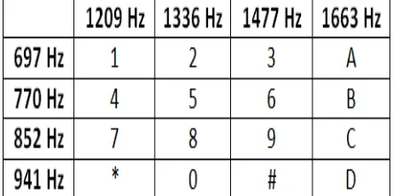
When you press a button in your mobile phone then a tone is generated having 2 frequencies. These 2 generated frequencies tones are row and column frequencies of that particular button. For example when you press the button 1 then a tone is generated which is the sum of 697 Hz and 1209 Hz. The table below shows the row and column frequencies of a DTMF keypad. Figure b. shows a DTMF decoder circuit.
ISSN(Online): 2320-9801
ISSN (Print): 2320-9798
I
nternational
J
ournal of
I
nnovative
R
esearch in
C
omputer
and
C
ommunication
E
ngineering
(An ISO 3297: 2007 Certified Organization)
Vol. 4, Issue 10, October 2016
These generated tones are decoded at receiver to determine which button is pressed. Now we use this DTMF tones to control the devices from remote area. In order to decode these DTMF tones at receiver we need to use a DTMF decoder. Decoder IC MT8870DE converts these tones into the digital output. For example if we press number ‘4’ then two frequencies are detected at receiving end from mobile keypad according to the table as show above. Then the digital output of DTMF decoder is ‘0100’. Similarly different tones with different frequencies as shown in table 1 will be generated for all individual keys on a keypad.
B. GSM MODULE/PHONE:
A GSM Module or a Handset is required at the receiver end. This will facilitate the reception of wireless Electromagnetic signals and its conversion to suitable audio output (As happens in a normal mobile communication system).
The GSM module/phone will work in auto answering mode. So the only purpose of this circuit is to receive the call and reproduce the DTMF tones dialled by the dialler. The audio output from this circuit will be directly passed to the DTMF decoder in order to recognize the DTMF tones. A figure of a GSM module is shown in fig. c.
Fig.c. GSM Module
C. RELAYS:
ISSN(Online): 2320-9801
ISSN (Print): 2320-9798
I
nternational
J
ournal of
I
nnovative
R
esearch in
C
omputer
and
C
ommunication
E
ngineering
(An ISO 3297: 2007 Certified Organization)
Vol. 4, Issue 10, October 2016
Copyright to IJIRCCE DOI: 10.15680/IJIRCCE.2016. 0410013 17183 Fig d. Array of Relay
IV.PROPOSED MODEL
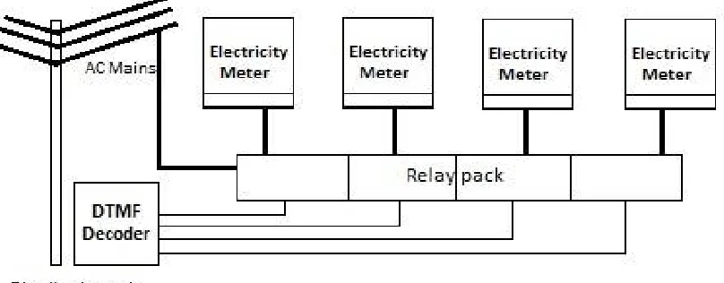
With the help of the above circuits and technology we can control up to 12 relays (as we have only 12 buttons on our phone’s dialler keypad) i.e. we can control the power supply of 12 different households using a single DTMF decoder circuit. This decoder circuit and the Relay circuit can be installed at the Power Line Distribution Pole (DP). The output of the relays can then be given to different households having the ordinarily installed Electricity meters.
4.1 EXAMPLE OF OPERATION:
Consider an ordinary SIM card with a 10digits mobile number is inserted in the GSM module. Say this number is 9876543210. This number is supposed to be known to the Electricity Distribution Board ONLY. Suppose 4 consumers are connected to this decoder circuit and are coded as say, 1 for the first house (electric meter), and 2 for the second house and so on.
ISSN(Online): 2320-9801
ISSN (Print): 2320-9798
I
nternational
J
ournal of
I
nnovative
R
esearch in
C
omputer
and
C
ommunication
E
ngineering
(An ISO 3297: 2007 Certified Organization)
Vol. 4, Issue 10, October 2016
V. SIMULATION RESULTS
The simulation shown below shows the working of the DTMF Decoder circuit. This stimulation is made using Proteus software. The Push Buttons here are acting as DTMF keypad. On pressing of particular push button a particular tone is generated. This tone is then sent to the DTMF Decoder IC MT8870D which recognizes the key pressed and generates a 4bit binary output. The output from the DTMF decoder is given to 4:16 Decoder IC. The decoder IC used gives an active high output at the particular pin depending upon the input. We have connected LED’s at output in order to check the proper operation of the relays and the DTMF decoder circuit.
VI.CONCLUSION AND FUTURE WORK
This paper describes how the use of smart switching using DTMF technology can benefits the Electricity Board. For implementation of this concept there no need for replacing the currently installed Electricity meters. Cost of implementation is almost negligible. So this leads in saving a company’s expenditure on manpower involved in recovering the money. This also speeds up the process of collection of money from defaulter consumers. Use of such type of remote switching eliminates the tedious and time consuming procedure that companies currently follow in order to recover their money. The Best part includes, application of this model is much cheaper than other alternative technologies including prepaid electricity meters.
REFERENCES
1. Nagoor Kani, ‘Digital Signal Processing’, second edition, Sec. 12.6, DTMF in Telephone Dialing
2. N.G. Palan, Digital Signal Processing, Sec. 9.2, Tech-Max publication, Pune, July 2005
3. Saddam, ‘DTMF Based Home Automation’, http://www.electronicshub.org/mobile-controlled-home-appliances-without-microcontroller/
4. Administrator, ‘Mobile Controlled Home Appliances without Microcontroller’, 20 OCT. 2015, http://www.electronicshub.org/mobile-controlled-home-appliances-without-microcontroller/
5. Administrator, ‘DTMF Controlled Home Automation System Circuit’, 30 SEPT. 2015, http://www.electronicshub.org/dtmf-controlled-home-automation-system-circuit/
6. RoboIndia, http://roboindia.com/tutorials/dtmf-home-automation-without-microcontroller
7. Tarun Agrawal, ‘DTMF based Home Automation System using Microcontroller’,
ISSN(Online): 2320-9801
ISSN (Print): 2320-9798
I
nternational
J
ournal of
I
nnovative
R
esearch in
C
omputer
and
C
ommunication
E
ngineering
(An ISO 3297: 2007 Certified Organization)
Vol. 4, Issue 10, October 2016
Copyright to IJIRCCE DOI: 10.15680/IJIRCCE.2016. 0410013 17185
8. Ganeev Singh, ‘Mobile Controlled Home Automation’,
http://www.engineersgarage.com/contribution/mobile-controlled-home-automation, 2014.
9. Xiao Meng, ‘DSP-base DTMF Decoder’, Arizona State University, 1996.
10. Wikipedia, ‘Dual-tone Multi frequency signaling, https://en.wikipedia.org/wiki/Dual-tone_multi-frequency_signaling.
11. Margaret Rouse, ‘DTMF (dual tone multi frequency)’, SEPT. 2005, http://searchnetworking.techtarget.com/definition/DTMF
12. J.S.Chitode, ‘Digital Signal Processing’, first edition 2008, Sec. 9.1 Dual tone Multi Frequency detection.
BIOGRAPHY
Akshay Omprakash Gehi is a student of Electronics and Telecommunication at Government College of Engineering Jalgaon. He is a final year student of Bachelor of Engineering.
Rupesh Digamber Chinawale is a student of Electronics and Telecommunication at Government College of Engineering Jalgaon. He is a final year student of Bachelor of Engineering.