University of Windsor University of Windsor
Scholarship at UWindsor
Scholarship at UWindsor
Electronic Theses and Dissertations Theses, Dissertations, and Major Papers
2013
Cold Sprayed Intermetallic Thermal Barrier Coatings
Cold Sprayed Intermetallic Thermal Barrier Coatings
Evgeny Leshchinsky University of Windsor
Follow this and additional works at: https://scholar.uwindsor.ca/etd
Recommended Citation Recommended Citation
Leshchinsky, Evgeny, "Cold Sprayed Intermetallic Thermal Barrier Coatings" (2013). Electronic Theses and Dissertations. 4727.
https://scholar.uwindsor.ca/etd/4727
This online database contains the full-text of PhD dissertations and Masters’ theses of University of Windsor students from 1954 forward. These documents are made available for personal study and research purposes only, in accordance with the Canadian Copyright Act and the Creative Commons license—CC BY-NC-ND (Attribution, Non-Commercial, No Derivative Works). Under this license, works must always be attributed to the copyright holder (original author), cannot be used for any commercial purposes, and may not be altered. Any other use would require the permission of the copyright holder. Students may inquire about withdrawing their dissertation and/or thesis from this database. For additional inquiries, please contact the repository administrator via email
Cold Sprayed Intermetallic Thermal Barrier Coatings
by
Evgeny Leshchinsky
A Dissertation
Submitted to the Faculty of Graduate Studies
through Mechanical, Automotive and Materials Engineering in Partial Fulfillment of the Requirements for
the Degree of Doctor of Philosophy at the University of Windsor
Windsor, Ontario, Canada
2012
978-0-494-79180-6 Your file Votre référence Library and Archives
Canada Bibliothèque etArchives Canada Published Heritage
Branch
395 Wellington Street Ottawa ON K1A 0N4 Canada
Direction du
Patrimoine de l'édition
395, rue Wellington Ottawa ON K1A 0N4 Canada
NOTICE:
ISBN:
Our file Notre référence 978-0-494-79180-6 ISBN:
The author has granted a
non-exclusive license allowing Library and Archives Canada to reproduce, publish, archive, preserve, conserve, communicate to the public by
telecommunication or on the Internet, loan, distrbute and sell theses
worldwide, for commercial or non-commercial purposes, in microform, paper, electronic and/or any other formats.
The author retains copyright ownership and moral rights in this thesis. Neither the thesis nor substantial extracts from it may be printed or otherwise reproduced without the author's permission.
In compliance with the Canadian Privacy Act some supporting forms may have been removed from this thesis.
While these forms may be included in the document page count, their removal does not represent any loss of content from the thesis.
AVIS:
L'auteur a accordé une licence non exclusive permettant à la Bibliothèque et Archives Canada de reproduire, publier, archiver, sauvegarder, conserver, transmettre au public par télécommunication ou par l'Internet, prêter, distribuer et vendre des thèses partout dans le monde, à des fins commerciales ou autres, sur support microforme, papier, électronique et/ou autres formats.
L'auteur conserve la propriété du droit d'auteur et des droits moraux qui protege cette thèse. Ni la thèse ni des extraits substantiels de celle-ci ne doivent être imprimés ou autrement
reproduits sans son autorisation.
Conformément à la loi canadienne sur la protection de la vie privée, quelques formulaires secondaires ont été enlevés de cette thèse.
December 11, 2012 Cold Sprayed Intermetallic Thermal Barrier Coatings
by
Evgeny Leshchinsky
APPROVED BY:
______________________________________________ Dr. J.- G. Legoux, External Examiner
National Research Council Canada
______________________________________________ Dr. A. Sobiesiak, Advisor
Department of Mechanical, Automotive & Materials Engineering
______________________________________________ Dr. V. Stoilov
Department of Mechanical, Automotive & Materials Engineering
______________________________________________ Dr. D. Green
Department of Mechanical, Automotive & Materials Engineering
______________________________________________ Dr. W. Kedzierski
Department of Physics
______________________________________________ Dr. R. Maev, Advisor
Department of Physics
______________________________________________ Dr. M. Mirhassani, Chair of Defense
iii
DECLARATION OF ORIGINALITY
I hereby certify that I am the sole author of this dissertation and that no part of this
dissertation has been published or submitted for publication.
I certify that, to the best of my knowledge, my dissertation does not infringe upon
anyone’s copyright nor violate any proprietary rights and that any ideas, techniques,
quotations, or any other material from the work of other people included in my
dissertation, published or otherwise, are fully acknowledged in accordance with the
standard referencing practices. Furthermore, to the extent that I have included
copyrighted material that surpasses the bounds of fair dealing within the meaning of the
Canada Copyright Act, I certify that I have obtained a written permission from the
copyright owner(s) to include such material(s) in my dissertation and have included
copies of such copyright clearances to my appendix.
I declare that this is a true copy of my dissertation, including any final revisions, as
approved by my thesis committee and the Graduate Studies office, and that this thesis has
iv ABSTRACT
Conventional thermal barrier coating (TBC) systems consist of a duplex structure with a
metallic bond coat and a ceramic heat-isolative topcoat. Several recent research activities
are concentrated on the development of improved multilayer bond coat and TBC
materials. This study represents an investigation performed for the aluminum based bond
coats, especially those with reduced thermal conductivities. Using alternative TBC
materials, such as metal alloys and intermetallics, their processing methods can be further
optimized to achieve the best thermal physical parameters. One example is the ten-layer
system in which cold sprayed aluminum based intermetallics are synthesized. These
systems demonstrated improved heat insulation and thermal fatigue capabilities
compared to conventional TBC. The microstructures and properties of the laminar
coatings were characterized by SEM, EDS, XRD; micromechanical and durability tests
were performed to define the structure and coating formation mechanisms. Application
prospects for HCCI engines are discussed. Fuel energy can be utilized more efficiently
DEDICATION
ACKNOWLEDGEMENTS
I would like to express my sincere gratitude to my advisers Dr. Maev and Dr. Sobiesiak
for their ideas, support, initiative and consideration that made this work possible. I would
like to thank our research and technical support team for doing outstanding work, their
dedication and expertise that they demonstrated during multiple experiments made in this
research. I would also like to give special thanks to my committee members and
especially my external examiner Dr. J. G. Legoux for taking time out to participate in my
dissertation defense. Finally, I would like to thank my family for their love, continuous
vii
TABLE OF CONTENTS
DECLARATION OF ORIGINALITY ... iii
ABSTRACT ... iv
DEDICATION ...v
ACKNOWLEDGEMENTS ... vi
LIST OF TABLES ... xi
LIST OF FIGURES ... xiii
CHAPTER I. INTRODUCTION 1.1 Review of HCCI Engine ...1
1.2 State of the Art of TBC for Engine Applications ...3
1.2.1 Common TBC Structure ...4
1.2.2 TBC Deposition Techniques ...6
1.3 YSZ TBC Shortcomings ...9
1.4 Novel TBC Development ...11
1.5 Cold Gas Dynamic Spray for TBC Deposition ...12
1.6 Reaction Synthesis Technology ...14
1.7 Research Objective ...16
1.8 Organization of Dissertation ...16
II. REVIEW OF LITERATURE 2.1 TBC for Diesel and HCCI Engines ...18
2.2 Overview of TBC Compositions and Properties ...26
2.3 Overview of TBC Deposition Technologies ...34
2.3.1 Chemical Vapour Deposition (CVD) ...35
2.3.2 Physical Vapour Deposition (PVD) ...37
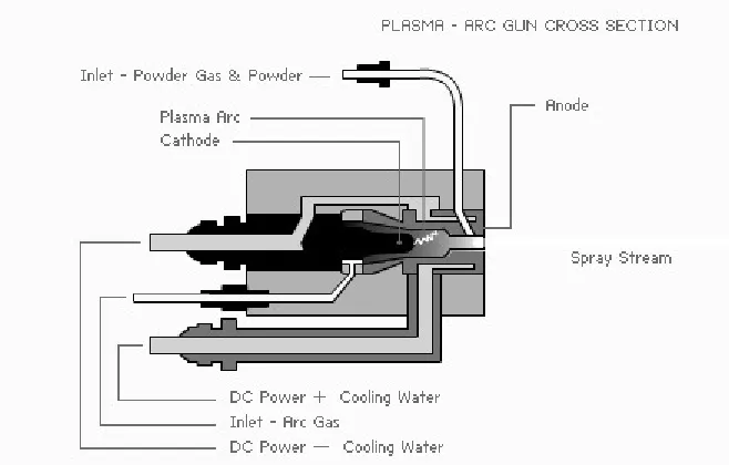
2.3.3 Plasma Spray ...39
2.3.4 Flame Spray ...40
2.3.5 High Velocity Oxy-Fuel Spray (HVOF) ...42
2.3.6 Electric Arc Spray ...43
III. EXPERIMENTAL SETUP AND METHODOLOGY
3.1 Cold Spray Equipment ...49
3.2 Coating Deposition ...50
3.3 Coating Post Treatment ...52
3.4 Coating Characterization ...52
3.4.1 Adhesion Testing ...53
3.4.2 Hardness Testing and Determination of the Elasticity Modulus via Micro-Indentation...54
3.4.3 Determination of Thermal Conductivity, Diffusivity and Specific Heat ...57
3.4.4 Determination of Thermal Expansion Coefficient ...62
3.4.5 Evaluation of Thermal Shock and Thermal Fatigue ...62
3.4.6 Examination of Microstructure ...67
3.4.7 XRF...68
3.4.8 Determination of Material Phases ...69
3.4.9 Summary ...71
IV. TBC DESIGN AND MODELING ANALYSIS 4.1 TBC Requirements for HCCI Engine ...72
4.2 TBC with Functionally Graded Structure ...73
4.2.1 Functionally Graded Materials ...75
4.2.2 Thermal Conductivity Bounds in Particulate Type Materials .77 4.2.3 Effect of Super-Deep Penetration for Controlling FGM Volume Fractions ...82
4.3 TBC Material Selection ...87
4.4 Effects of Reaction Synthesis on Attaining of Intermetallic TBC96 4.5 TBC Multilayer Design ...102
4.6 The Effect of TBC on Piston Temperature using FEA...103
4.7 Summary ...107
V. TBC DEPOSITION AND POST TREATMENT TECHNOLOGIES 5.1 Cold Spray (CS) Processing Parameters and Optimization ...108
5.1.1 Travel Speed of Cold Spray (CS) Nozzle ...109
5.1.2 Effect of Powder Hopper Settings ...112
5.1.3 Effect of Powder Feeding Rate ...116
5.1.4 Effect of the Step Size between Adjacent Passes ...118
5.1.5 Effect of Using Different Types of Carrier Gases ...120
5.2 Super Deep Penetration (SDP) Characterization Metal Alloy
Powders ...122
5.3 Synthesis of Intermetallics in Multilayer CS Coatings ...132
5.3.1 Determination of Intermetallic Diffusion Zones ...133
5.3.2 Determination of Intermetallic Growth Kinetics ...139
5.4 Summary ...147
VI. TBC PROPERTIES AND RESULTS ANALYSIS 6.1 Thermal Conductivity and Thermal Diffusivity of Intermetallic TBC ...148
6.1.1 Thermal Conductivity & Diffusivity of SHS-717 Iron – Based Intermetallics ...150
6.1.2 Thermal Conductivity & Diffusivity of AMS-4777 Nickel – Based Intermetallics ...152
6.1.3 Thermal Conductivity & Diffusivity of A-4783 Cobalt – Based Intermetallics ...155
6.1.4 Influence of Intermetallic Phases and Temperature on Thermal Conductivity ...156
6.2 Coefficient of Thermal Expansion of Intermetallic TBC ...160
6.3 Adhesion of Multilayer Intermetallic TBC to Aluminum Substrate ...161
6.4 Microhardness Characterization of Multilayer Intermetallic TBC165 6.4.1 Determination of Microhardness in Composites and its Evaluation Parameters ...166
6.4.2 Microhardness Characterization of Individual Intermetallic TBC ...170
6.4.3 Comparison of Microhardness of Al Matrix with Different Alloying Elements ...173
6.4.4 Comparison of Microhardness of Different Intermetallics in Al Matrix ...175
6.5 Elasticity of Multilayer Intermetallic TBC ...176
6.6 SEM, EDS & XRD analysis of Multilayer Intermetallic TBC .180 6.6.1 SEM, EDS & XRD analysis of SHS-717 – Al Composites ..180
6.6.2 SEM, EDS & XRD analysis of AMS-4777 – Al Composites185 6.6.3 SEM, EDS & XRD analysis of A-4783 – Al Composites ...188
6.7 Thermal Fatigue Tests of Multilayer Intermetallic TBC ...192
6.7.1 Multilayer Intermetallic TBC Characterization after Fatigue Test ...193
6.7.2 TBC Metallographic Characterization after Fatigue Test ...196
6.7.4 Fracture Topography Characterization of TBC after Fatigue
Test ...203
VII. CONCLUSIONS AND FUTURE RECOMMENDATIONS 7.1 Summary of Technological Parameters ...207
7.2 Summary of Thermo-Physical and Mechanical Properties of TBC ...209
7.3 Conclusions...211
APPENDICES FEI Quanta 200 FEG high resolution SEM with EDAX Energy Dispersive Spectroscopy (EDS) data ...213
Shimadzu DUH-211 Dynamic Ultra Micro-Hardness (DUH) tester data ...231
REFERENCES ...237
LIST OF TABLES
Table 1.1 Properties of YSZ TBCs at room temperature………...7
Table 2.1 Operating temperatures and stress states comparison of TBC for diesel
engines...22
Table 2.2 Properties of the coatings and substrate materials……….30
Table 4.1 Powder compositions used in the experiment………...……….92
Table 4.2 Values of the activation energy for diffusion growth of the iron –
aluminum intermetallic layer………...100
Table 5.1 CS coating thickness as a function of hopper vibration setting……...…113
Table 5.2 CS coating thickness as a function of powder level in the hopper for two
different powders……….115
Table 5.3 Influence of CS parameters on pulsing effect determined by visual
examination of the coatings……….119
Table 5.4 Influence of step size on the coating thickness for Al-1 and Al-2 mixtures
with different flow ability………119
Table 5.5 Approximation coefficients for the function of average concentration of
embedded particles………...…129
Table 5.6 Approximation coefficients for the function of average thickness of SPD
layers………....129
Table 5.7 Micro-hardness of the aluminum matrix of the composite coatings……131
Table 6.2 Microhardness of multilayer coatings after heat treatment at various
temperatures……….170
Table 6.3 Elastic properties of aluminum layer in intermetallic TBC...177
Table 6.4 EDS analysis of AMS-4777 - Al composite after sintering at 550oC..…186
Table 6.5 EDS analysis of A-4783 - Al composite after sintering at 625oC……....191
Table 7.1 Cold Spray parameters selection for aluminum layers………208
Table 7.2 Super Deep Penetration parameters selection for………...…….209
Table 7.3 Thermo-Physical properties of intermetallic TBC………...210
Table 7.4 Mechanical properties of intermetallic TBC………....210
LIST OF FIGURES
Figure 1.1 Compression ignition, Spark ignition and HCCI combustion……….……2
Figure 1.2 Schematic of the three layer thermal barrier coating………...5
Figure 1.3 Plasma spray deposited YSZ coating………...…7
Figure 1.4 Gas Dynamic Spray operating systems………..13
Figure 2.1 Piston head with TBC coating………..…….21
Figure 2.2 Piston top surface heat flux variation during one engine cycle………….22
Figure 2.3 Comparison of the gas temperature on the piston top surface………...…23
Figure 2.4 Schematic illustration of temperature and stress development in TBC….24 Figure 2.5 Variation of stress ratios with the increase of thermal expansion mismatch on the coating – substrate interface………...………….25
Figure 2.6 Variation of thermal expansion and coefficients of thermal expansion of YSZ ceramics, Fe3Al intermetallics and Al-Si alloys…………...……….26
Figure 2.7 Thermal conductivity, k, vs. thermal expansion coefficient, a, diagram for thermal barrier materials………28
Figure 2.8 Thermal diffusivity, α, vs. thermal conductivity, k, diagram for thermal barrier materials……….………29
Figure 2.9 Fe3Al-5%Cr alloy following the plastic strain at 1075 K………..31
Figure 2.10 Thermal expansion coefficient, a vs. temperature for Fe3Al-5% Cr and Fe-40%Al………....31
Figure 2.11 Thermal conductivity, k, vs. temperature of oxide based TBC………….33
Figure 2.13 Schematic of PVD process...38
Figure 2.14 Schematic of Plasma Spray...39
Figure 2.15 Schematic of Flame Spray...41
Figure 2.16 Schematic of HVOF...42
Figure 2.17 Schematic of Electric Arc Spray...43
Figure 2.18 Schematic of De-Laval nozzle………...………46
Figure 2.19 Schematic of Cold Spray machine produced by Centerline Ltd...46
Figure 2.20 Different types of cold spray techniques positioned on the velocity vs. particle size map………....………48
Figure 2.21 Particle temperatures vs. velocity map for thermal spray techniques……48
Figure 3.1 Experimental setup of SST equipment for spraying of TBC...50
Figure 3.2 Example of the piston with cold sprayed TBC……….……….51
Figure 3.3 The tensile test set-up and the adhesion specimen typical failures…...….54
Figure 3.4 Shimadzu DUH-W201S micro-hardness tester……….55
Figure 3.5 Vickers hardness indenter based on diagonal length...56
Figure 3.6 Example of Shimadzu DUH-W201S loading – unloading diagram……..57
Figure 3.7 Schematic of light flash method utilized in Netzsch LFA-447…………..58
Figure 3.8 Dimensionless plot of rear surface temperature change……...………….60
Figure 3.9 Thermal shock and thermal fatigue experiment set-up...65
Figure 3.10 Thermal shock specimen preparations……….………..67
Figure 3.11 XRD analysis principles………...…….70
Figure 3.12 Schematic of the goniometer Scintag XDS 2000 used in experiment…...71
Figure 4.2 Typical structure of FGM………..76
Figure 4.3 Heat flux vectors for dispersion of spheres in a continuous medium……78
Figure 4.4 Schematic representations of the structures assumed by each model and relative thermal conductivity for each case of Equations (4.4 – 4.8)……82
Figure 4.5 Schematics of the super-deep penetration phenomenon………...….84
Figure 4.6 Composition dependence of thermal conductivity at 300K of NiAl, CoAl and FeAl………...…..88
Figure 4.7 Fe-Al phase diagram showing thermally stable Fe – Al phases up to the temperatures of ~ 1100°C...89
Figure 4.8 Ni-Al phase diagram showing thermally stable Ni – Al phases up to the temperatures of ~ 1130°C...90
Figure 4.9 Co-Al phase diagram showing thermally stable Ni – Al phases up to the temperatures of ~ 1180°C...91
Figure 4.10 SEM image of SHS-717 powder particles……….93
Figure 4.11 SEM image of AMS-4777 powder particles...94
Figure 4.12 SEM image of A-4783 powder particles...95
Figure 4.13 SEM image of Al-101 powder………...………96
Figure 4.14 The experimental results of sintering of SHS-717 particles with aluminum matrix………98
Figure 4.15 The dependence of the parabolic rate constant in terms of lnk………….98
Figure 4.16 The binary phase diagram of Al - Fe with the marked region of the prevailing phase obtained at the final stage of reaction synthesis…...…100
Figure 4.18 Schematic of piston multilayer TBC………..…………..103
Figure 4.19 Piston mesh rendered by Abaqus 6.10 with boundary conditions set on
the external surfaces……….………106
Figure 4.20 Piston temperature distributions through the piston crown without TBC;
piston material is selected as Al-Si A-13 alloy...106
Figure 4.21 Piston temperature distribution of Fe-Al coated piston…………...……107
Figure 5.1 Schematic of a robot scan pattern with spray direction and step size…..110
Figure 5.2 Effect of traverse speed on the average thickness of aluminum
coating...111
Figure 5.3 Comparison of surface quality of coatings deposited at different
traverse speed………...……111
Figure 5.4 Schematic of the powder feeder used in the experiment…………...…..112
Figure 5.5 Comparison of surface quality of coatings deposited at different
hopper vibration settings………..……114
Figure 5.6 Influence of powder level in the hopper on coating surface quality...116
Figure 5.7 The effect of pulsing occurring in the CS nozzle………117
Figure 5.8 Effect of the powder feeding rate on the coating thickness for
Al-1 type powder………...117
Figure 5.9 Appearance of coating surface deposited using different step sizes...120
Figure 5.10 Variation of the coating thicknesses for Al-1 and Al-2 type powders
deposited using different carrier gasses………..….121
Figure 5.12 Optical images of aluminum layers with embedded SHS-717 particles
deposited at 500 °C and processing parameters...124
Figure 5.13 SPD characteristics of SHS-717 powder……….……126
Figure 5.14 SPD characteristics of AMS-4777 powder……….….…127
Figure 5.15 SPD characteristics of A-47783 powder………..…128
Figure 5.16 SEM images of SDP layers for powders……….…….130
Figure 5.17 SEM images of individual stainless steel layers as sprayed…………....133
Figure 5.18 SEM images of individual stainless steel layers as sprayed………135
Figure 5.19 Location of section plane of stainless steel particles in specimen ……..136
Figure 5.20 Optical images of AMS-4777 composite coatings……….….138
Figure 5.21 SEM images of the specimens annealed at 625 °C………..140
Figure 5.22 Dependences of aluminide intermetallic layers growth on time………..142
Figure 5.23 Optical images of coating microstructure after annealing at 600 oC…...143
Figure 5.24 SEM images of A-4783 Co-Ni-Cr alloy particles………144
Figure 5.25 Images of SHS-717 in aluminum matrix composite after sintering at the temperature of 575oC during 2 hours………..….145
Figure 5.26 EDS of the intermetallic phases of SHS-717 – aluminum composite showing phase distribution after annealing at 550oC during 1 hour...146
Figure 6.1 SHS-717 iron – based intermetallic TBC………...….151
Figure 6.2 AMS-4777 nickel – based intermetallic TBC……….….153
Figure 6.3 Thermal conductivities of various phases in Ni-Al alloys………..…….155
Figure 6.5 Thermal conductivity of aluminides as a function of Al concentration at
room temperature……….………157
Figure 6.6 Thermal conductivities of the intermetallic layers in TBC made from
SHS-717, AMS-4777 and A-4783………..………….158
Figure 6.7 Coefficients of thermal expansions of intermetallic and aluminum layers
of TBC made from SHS-717 , AMS-4777 and A-4783……….…….…160
Figure 6.8 Adhesive strength of SHS-717 coatings at various conditions……...….163
Figure 6.9 Adhesion specimen of SHS-717 – Al coating annealed at ~ 575 °C...164
Figure 6.10 The approximation of the unloading curve for microindentation………166
Figure 6.11 Imprints of the indents on the composite coating………...……….168
Figure 6.12 The typical diagrams for “load-displacement” on Aluminum………...169
Figure 6.13 Microhardness of intermetallic particles and aluminum matrix in
SHS-717 iron based coating...172
Figure 6.14 Microhardness of intermetallic particles and aluminum matrix in
AMS-4777 nickel based coating……….……….172
Figure 6.15 Microhardness of intermetallic particles and aluminum matrix in
A-4783 cobalt based coating………..…..173
Figure 6.16 Comparison of Al layer microhardness in examined Fe-Al, Ni-Al and
Co-Al composites...174
Figure 6.17 Comparison of the microhardness for the intermetallic particles of Fe-Al,
Ni-Al and Al-Co composites...176
Figure 6.18 Elastic properties of aluminum layer in the intermetallic TBC……..….179
Figure 6.20 Binary phase diagram Fe-Al marked with phases obtained during the
reaction synthesis……….……182
Figure 6.21 SEM images of SHS-717- Al phases after sintering at 625°C...183
Figure 6.22 XRD analysis of SHS-717- Al intermetallics after sintering at different
temperatures……….184
Figure 6.23 SEM images of AMS-4777- Al phases after sintering at 550°C……….185
Figure 6.24 EDS analysis of AMS-4777 – Al phases after sintering at 625oC……...187
Figure 6.25 XRD analysis of AMS-4777 – Al multilayer coating sintered at different
temperatures……….187
Figure 6.26 Binary phase diagram Al – Ni marked with phases obtained during
the reaction synthesis………...………188
Figure 6.27 EDS analysis of A-4783 – Al phases after sintering at 550oC...189
Figure 6.28 Binary phase diagram Al – Co marked with phases obtained during
the reaction synthesis………...190
Figure 6.29 SEM images of A-4783- Al phases after sintering at 625°C…………...191
Figure 6.30 XRD analysis of A-4783 – Al multilayer coating sintered at 625°C...…192
Figure 6.31 Schematic of the heat flux test for measuring the thermal fatigue
properties………..194
Figure 6.32 Pyrometer reading of the surface temperature fluctuations……….195
Figure 6.33 Micro-hardness of SHS-717, AMS-4777 and A-4783 particles after
thermal fatigue test………...……195
Figure 6.34 SHS-717 – Al coating after thermal fatigue test………..196
Figure 6.36 A-4783 – Al coating after thermal fatigue test………198
Figure 6.37 Load - depth indentation diagram of SHS-717 - Al intermetallic particle
after thermal fatigue test………..199
Figure 6.38 Load - depth indentation diagram of AMS-4777 - Al intermetallic
particle after thermal fatigue test……….200
Figure 6.39 Load - depth indentation diagram of A-4783 - Al intermetallic particle
after thermal fatigue test………..201
Figure 6.40 Load - depth indentation diagram of the TBC aluminum matrix after
thermal fatigue test………...202
Figure 6.41 SEM images of the fractured surfaces of SHS-717 multilayer intermetallic
coating after thermal fatigue test………...203
Figure 6.42 SEM images of the fractured surfaces of AMS-4777 multilayer
intermetallic coating after thermal fatigue test………204
Figure 6.43 SEM images of the fractured surfaces of A-4783 multilayer intermetallic
CHAPTER I
INTRODUCTION
Stringent emissions and fuel economy regulations set forth by the Environmental
Protection Agency (EPA) and Canadian Environmental Protection Act (CEPA) have
forced the automotive industry in North America to seek a low cost and reliable solution
to meet these new requirements. Homogeneous Charge Compression Ignition (HCCI) is
believed to be one of the potential answers to the problem. The HCCI combustion
process combines the benefits of the two main Internal Combustion Engines (ICE)
technologies: Spark Ignition (SI) and Compression Ignition (CI), which are reflected in
its name: homogeneous mixture and compression ignition. While the HCCI process
utilizes the advantages of each technology, one of the hurdles preventing the successful
implementation of the HCCI engine to the main automotive market is how to control auto
ignition and heat supply required for steady operation. In this research, Thermal Barrier
Coatings (TBC) are designed and investigated to capture the energy normally wasted by
the engine through the engine exhaust and cooling systems thus helping to create the
appropriate conditions for HCCI cycle. The captured energy can be used as an additional
heat source necessary to initiate HCCI combustion. As the first step, this was achieved by
modifying engine pistons with thermal barrier coatings and the possibilities of applying
TBC to the cylinder head deck, valve heads and cylinder liners were evaluated.
1.1 Review of HCCI Engine
Homogenous Charge Compression Ignition, (HCCI), is currently a topic of
conventional four stroke cycle as are most of the mass produced engines available in the
automotive market. This combustion method combines the advantages of the two mass
produced alternatives: Spark Ignition (SI) and Compression Ignition (CI). However,
unlike either of these conventional engines, combustion occurs simultaneously
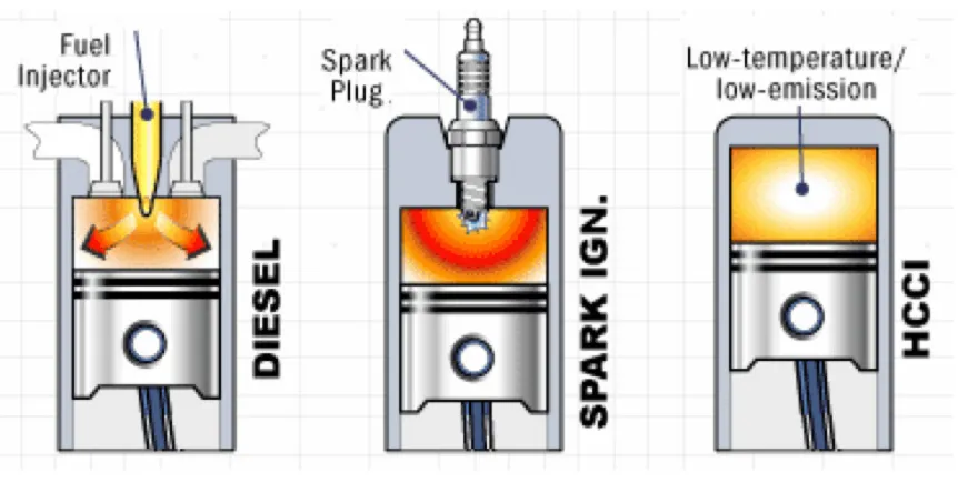
throughout the cylinder volume rather than in a flame front (Figure 1.1).
Figure 1.1 Compression ignition, Spark ignition and HCCI combustion.
HCCI is considered a promising concept since the emissions levels produced are
comparable to those of a SI engine while the thermal efficiency obtained is comparable to
the level achieved in CI diesel engine. Like an SI engine, the charge is well mixed which
minimizes particulate emissions; lean and ultra-lean air/fuel mixtures up to 80% reduce
the combustion temperature thus eliminating NOx emissions. Similar to a CI engine, the
HCCI engine has no throttling losses, which lead to high efficiency up to 55%. The
cumulative effect of implementation of HCCI cycle may result in reducing fuel
However, despite of the apparent advantage what HCCI engines provide in
comparison to a conventional one, it still hasn’t reached the high volume production due
to the significant technical hurdles such as: controlling ignition timing and burn rates;
extending the operating range of HCCI cycle to high engine loads, which may result in
excessive in-cylinder pressure causing knock and parts damage; and cold start and
transient response of HCCI cycle to constantly changing engine environment conditions.
HCCI is a complex mode of combustion to achieve and control. The main topics
of the concurrent HCCI research involve increasing in-cylinder temperatures and
pressures with complex methods. There are multiple methods of using external heat
sources for HCCI engine, but so far there is no viable method for using the heat contained
within the engine as the source needed to create in-cylinder conditions necessary for
HCCI. An internal combustion engine is an excellent heat source and thus an additional
external heat source might not be necessary. An engine designed or modified with this
principle in mind could be able to operate in a sustaining HCCI condition without
external energy input. The research presented here is to explore the potential use of
thermal barrier coatings as a method to capture the heat necessary to create the
appropriate conditions for HCCI cycle.
1.2 State of the Art of TBC for Engine Applications
Concurrent application of thermal barrier coatings on the elements of a
combustion chamber in diesel engines offer advantages including fuel efficiency, multi
transferred to the cooling system, however the insulation of the combustion chamber
influences the combustion process and exhaust emission characteristics. The reports on
diesel engine performance often contradict each other. In some investigations, the
significant benefits are the increase in engine power by 8%, significant decrease in the
specific fuel consumption by 9% and the increase in the temperature of exhaust gases by
70 K [1], which in turn, can be recovered by turbo-charging. Some data about a
detrimental effect of TBC on the engine economy may be found in literature [1]. It may
be attributed to the longer burn duration for coated pistons and injection timing
discrepancies. It is shown in [2] that in diesel engines the radiation accounts for about
20-40% of the total surface heat transfer and ceramics are translucent to the infrared light,
which makes concurrent TBC ineffective. In contrast, the results obtained on spark
ignition engines are convergent and authors [3] found 6% improvement in fuel economy
and a decrease in unburned hydrocarbon levels.
1.2.1 Common TBC Structure
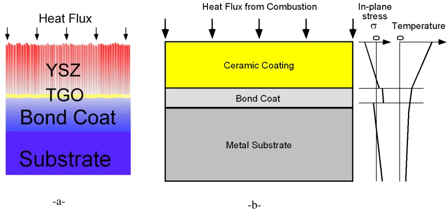
Usually, the structure of common TBC [4] consists of three layers (Figure 1.2).
The topmost layer is a ceramic material that constitutes the actual heat shield. The
material choice is usually Yttria Stabilized Zirconia (YSZ) because of its unique
combination of thermo-mechanical properties. First, doping ZrO2 with 6–8 % (weight)
Y2O3 ensures that the resulting YSZ adopts the tetragonal phase at the temperature range
475-775 K. Secondly, it is used due to its low thermal conductivity of 2-2.5 W/mK vs.
~50 W/mK for steel and relatively high thermal expansion of ~9 mm/mmK vs. ~12
coefficient of thermal expansion is well matched to the metal substrates so that stress
buildup due to thermal expansion mismatch is minimized. The thermal cycling induced
phase transitions, which otherwise would occur in pure Zirconia causing stress buildup,
are avoided. YSZ has one of the lowest thermal conductivities of all ceramics, because it
possesses an unusual defect structure that scatters phonons thereby hindering heat
transport [4]. Finally, YSZ has a low density, which minimizes the weight, is very hard
and therefore quite resistant toward foreign-body physical damage [5, 6].
Figure 1.2 (a) - schematic of the three layer thermal barrier coating. It features Ni-Pt-Al
bond coat approximately 50 µm thick, YSZ ceramic topcoat of approximately 100 µm thick. A thin <10 µm layer of α-Al2O3 is formed in between YSZ and bond coat during deposition and operation and is known as thermally grown oxide (TGO) layer [4].
(b) - schematic of stress state resulting from the applied thermal load on the
TBC in a diesel engine [7].
YSZ layer is not deposited directly onto the substrate. One reason for this is that
YSZ is transparent to oxygen diffusion and during operation oxygen would diffuse into
the interface and oxidize the metal, thus forming fast growing oxides that would cause
early coating spallation [6]. Therefore, a bond coat (BC) alloy is deposited onto the
substrate before deposition of the YSZ. Two different classes of BC alloys exist. Firstly,
~100 µm thick MCrAlY alloys (where M stands for metal Co or Ni) are in use since the
1960s. Secondly, ~ 40 – 60 µm thick Pt,Ni Aluminides have been developed fairly
recently and they are more oxidation resistant but less ductile than MCrAlY. Both types
of BCs ensure good adhesion and corrosion protection [5]. Together with top coat (TC)
they can lengthen the lifetime of the substrates by lowering the temperature and reducing
the stress forces leading to creep failure and thermal fatigue by taking upon themselves
the severe environmental conditions.
1.2.2 TBC Deposition Techniques
There are two main methods for preparation of YSZ TBCs: by plasma spraying
(PS) and electron beam physical vapor deposition (PVD). The coatings produced vary by
thickness, structure and thermo-mechanical characteristics (Figure 1.3). Table 1.1
presents the comparison of YSZ TBC properties produced by PVD and PS.
In the PS process, feedstock powders are melted and accelerated to high
velocities, impinging upon the substrate, and rapidly solidifying to form a “splat”, i.e. a
flattened particle. The deposit develops by successive impingement and inter-bonding
Property/characteristic PVD PS
Thermal conductivity (W/mK) 1.5 – 1.9 0.8 – 1.1
Surface roughness (mm) 1.0 10.0
Adhesive strength (MPa) 400.0 20 – 40
Young’s modulus (GPa) 90.0 200.0
Erosion rate (normalized to PVD) 1 7
Growth rate (µm/h) 200 – 300 10 000
Production cost High Low
Table 1.1 Properties of YSZ TBCs at room temperature [19]
Figure 1.3 (a) - plasma spray deposited YSZ showing its’ coarse, disc-like pores aligned
(b) - an electron beam physical vapor deposited YSZ coating with elongated
pores aligned perpendicular to the substrate surface.
The splats are separated by inter-lamellar pores resulting from rapid solidification
of the lamellae, very fine voids formed by incomplete inter-splat contact or around
unmelted particles and cracks due to thermal stresses. The pores and cracks interfere with
the direct flow of heat, resulting in lower thermal conductivity close to 1 W/mK. In
addition, PS YSZ TBCs have a high processing efficiency and low cost. Nevertheless,
although PS process has many advantages over other traditionally used thermal spray
processes, compared with EB-PVD process, some of the defects such as voids,
inclusions, and poor adhesion strength between YSZ-TBCs and substrates still remain,
which lead to the bond coat oxidation and decrease the durability of YSZ TBC’s.
In PVD process, vapors are produced by heating the source material with an
electron beam in a vacuum chamber and the evaporated atoms condense on the substrate.
Crystal nuclei form on favored sites, growing laterally and in thickness to form individual
columns (Figure 1.3 b). Thermal expansion mismatch between ceramic and metallic
components is better accommodated by the columnar morphology, than by the porosity
and micro-cracking of PS YSZ TBCs [108]. The adhesive strength between the substrate
and YSZ is ten times higher for PVD than for PS YSZ TBCs, which is an important
factor in preventing premature spallation of the YSZ layer [109]. So, the PVD process
offers the advantage of a superior strain, erosion and thermal shock tolerant behavior for
the coatings due to their columnar microstructure. These coatings also retain an
YSZ TBCs do [110]. Nevertheless, these properties are gained at the expense of higher
thermal conductivity and production cost [111].
1.3 YSZ TBC Shortcomings
While PS and PVD can produce high quality coatings, they still suffer from
several limitations. First of all, inevitably a distinct interface between TC and BC in two
layer coatings results in discontinuities of the materials’ properties across the thickness of
the coating. As a result, residual stresses develop in TBCs due to the thermal expansion
mismatch between the different layers of the TBC initially during deposition (~3GPa)
and later on during the exploitation (~3.9GPa) [117]. Residual stresses can give rise to
deformation of the coated work pieces and initiate micro-cracks at the TC/BC interface.
Subsequently, the thermally grown oxide layer (TGO), mainly consisting of α-Al2O3 and
Cr2O3, forming along the irregular TC/BC interface, scales at cyclic high-temperature
exposure due to Al depletion and consequent oxidation of Cr, Ni resulting in a very high
growth rate and increases the volume of the TGO. It is considered to be the main cause
for creating internal stress at TC/BC interface, which eventually affects the coating
durability [118].
In this context, the major factors influencing the lifetime of YSZ TBCs are:
1. thermal expansion mismatch between YSZ TBCs and substrates;
2. uncontrolled growth rate of TGO and the associated buildup of strain
energy;
4. increase of thermal conductivity of YSZ TBCs during service due to the
TC/BC spallation of and simultaneously decrease of its high-temperature capability.
Since flaws at the TC/BC interface are primarily responsible for initiating coating
debonding and accelerating the oxidation process at TGO, the coating deposition
techniques represent a great challenge in terms of eliminating substrate imperfections,
surface preparation, process and coating quality control. Thus, all techniques for TBC
deposition are relatively complex and expensive. Although plasma spray processing is a
well established method for forming thick coatings, in coatings thinner than 100 µm it is
difficult to control material properties because the acceleration process is not yet efficient
enough. The primary imperfection associated with plasma spraying, however, is its high
processing temperature, making a number of substrate materials unfit for treatment due to
local heating, oxidation and thermal deformations. Further, the high-temperature jet that
is incident on the product surface intensifies chemical and thermal processes, causing
phase transformations and the appearance of oversaturated and non-stoichiometric
structures, which bring about structural changes in the substrate material. Also, the high
cooling rates result in the hardening of these heated materials and building up high
residual stresses. Finally, the liberation of gases during crystallization brings about both
porosity and the appearance of micro-cracks.
Even though the PVD process for TBC fabrication offers significantly better
adhesive strength, its thermal conductivity is twice higher than PS YSZ TBC. Besides
processing time is long and the costs are very high. Further, the columnar morphology of
the PVD YSZ TBCs ceramic top coat allows easier penetration of corrosive fuel and
gasses into TGO and consequent propagation of cracking (horizontal and vertical),
sintering of TC Zirconia, particle erosion, TGO degradation and ultimate coating
debonding.
1.4 Novel TBC Development
Even though important advances have been made in recent years to the
development of ceramic based TBCs, they are not yet widely applied in mass production.
Besides the important economic considerations, the reliability of ceramic TBCs is also a
major issue including difficulties in predicting their service lifetime due to inherent brittle
behaviour. This situation probably requires not only application of state-of-the-art
processing methods, but also novel material compositions capable of producing TBCs
with high qualities. Finally, further efficiency improvements require TBCs to be an
integral part of the component, which in turn, require reliable and predictable TBC
performance.
One of the developments taking place over the last two decades has been devoted
to metal base thermal barrier coatings (MBTBC). For such metals with highly refined
microstructure there is a potential of limiting thermal conductivity by incorporating grain
boundary scattering as an extrinsic phonon-scattering phenomenon [11]. This type of
novel materials includes quasi-crystalline, nano-crystalline and amorphous metals. A
at elevated temperatures: glassy materials tend to crystallize and nano-crystalline
materials tend to rapidly coarsen and lose initial advantages of being nano-crystalline.
However, nano-composites and intermetallics are expected to be more resistant to
coarsening, but early investigations of Zirconia / Alumina laminates indicate they
become spheroid and then coarsened. Nevertheless, the potential of nano-composites and
intermetallics for thermal barrier applications has not been explored systematically. Our
particular interest in this research would be intermetallic composites that feature both
nano-crystalline and amorphous structures and resist coarsening under high temperature
conditions while being used as thermal barrier coatings.
1.5 Cold Gas Dynamic Spray for TBC Deposition
Cold gas dynamic spray, or cold spray (CS), is a rapidly emerging coating
technology in which spray particles in a solid state are deposited on a substrate via high
velocity impact at temperatures lower than the melting point of the powder material. In
this method, solid particles ranging from 10 to 50µm in size are introduced by means of a
pressurized powder feeder into the high-pressure, high-temperature chamber of a
converging-diverging de Laval nozzle and are subsequently accelerated into a supersonic
stream by the gas (Figure 1.4 a). Even though the carrier gas is preheated up to 500 ~ 700
K to archive high velocities of flow from Mach 1 up to Mach 3, the deposited particles
are still “cold” because this temperature is still below the melting point of most metal
powders. Moreover, the short time span that they spend in the gas stream is somewhere
Figure 1.4 Gas Dynamic Spray operating systems that accelerate micron-sized particles to
high velocities by supplying the particles in the flow of supersonic nozzle:
a – axial injection [Assadi et al., 2003];
b – radial injection.
The deposition of particles takes place through intensive plastic deformation upon
impact in a solid state at a temperature well below the melting point of spray materials.
Consequently, the deleterious effects inherent to conventional thermal spraying such as -a-
oxidation, composition change, grain growth and other problems can be minimized or
eliminated. During deposition, cold sprayed materials experience only minor changes in
microstructure and little oxidation of decomposition. Most metals such as Cu, Al, Ti, Ni
and Ni-based alloys can be deposited by CS [32], even cermets [33] and ceramics [34]
can be embedded into a substrate to form a thin layer coating. A unique feature of CS is
the ability to generate a wide range of deposition layer thicknesses ranging from tens of
microns up to several centimeters. In this regard this process extends beyond the concept
of “coating” on a substrate providing a means for developing three-dimensional
structures [39].
1.6 Reaction Synthesis Technology
Fe-Al intermetallic compounds have drawn much attention as materials for
medium-to high-temperature applications owing to their unique properties such as good
mechanical properties, low density, low cost, low thermal conductivity and excellent
corrosion resistance in oxidizing and sulfidizing environments [112]. However,
industrial applications of these alloys as a bulk material have been hampered due to their
low ductility and processing problems, which result from a large difference in the melting
points of Al and Fe and the exothermic nature of formation of aluminides [113]. To
utilize their excellent oxidation and corrosion resistance, Fe-Al intermetallic compounds
have been employed as coatings, which are prepared by several coating techniques such
as plasma (PS), high velocity oxy-fuel (HVOF), wire-arc and flame spraying. However,
high oxide content in the obtained coating and deteriorates the overall thermo-mechanical
properties, oxidation and corrosion resistances [114].
Recently, the newly emerging cold spray (CS) process has been proven to be able
to overcome several disadvantages of conventional thermal spraying due to its low
processing temperature. The low temperature characteristic, high deposition rate as well
as relatively low cost make the CS technique an efficient process for the fabrication of
metals and composites [115]. Moreover, cold spraying of Ti, Ni and Al powder mixtures
show that the dense composites can be produced using mixed powders and the
consequent annealing treatment may lead to the intermetallic phase formation [116]. The
deformation during the cold spraying process would disrupt any thin surface scale such as
oxides and expose fresh, active material, which is brought into contact under highly
localised pressure forming strong physical bonds. As a result, cold sprayed composites
may be expected to form intermetallic coatings by post-spray annealing treatment at
relatively low temperature.
However, the use of this method requires precise control of the self-propagating
high-temperature synthesis (SHS), which is utilized as one of the sources of heat during
the sintering process [46]. SHS is very rapid and its strong exothermic nature causes
unwanted porosity due to the local boiling of Aluminum at high temperature in the
composite material structure [44]. Studies [44-46] show the great complexity of the
phenomena taking place during the pre-sintering process correlated with the diffusion and
correlated with many factors such as powder particle size, annealing temperature, heating
rate and the chemical composition of the sample.
1.7 Research Objective
The overall goal of this study is to obtain, assess and understand the
high-temperature behavior and thermo-mechanical properties of intermetallic Fe-Cr-Co-Ni-Al
coatings made by cold spray; investigate in depth the effect of the annealing treatment on
the intermetallic compound formation and the microstructure evolution of cold sprayed
composite coatings.
The specific objectives can be summarised as follows:
1. Develop intermetallic thermal barrier coatings obtained by combination of cold spray
and reaction synthesis technology;
2. Determine the thermo-mechanical properties of intermetallic TBC at ambient and
engine exploitation temperatures and their variation after exposure to high
temperature;
3. Examine the microstructure of intemetallic TBC, characterize its evolution during all
fabrication and testing steps and evaluate its influence on the thermo-mechanical
properties of TBC.
1.8 Organization of Dissertation
This dissertation will report on the process that was followed in order to achieve
1. Literature review of the work related to this study is provided in Chapter 2;
2. Details of the experiment equipment and set-up are presented in Chapter 3;
3. TBC design and associated technological development are explained in Chapter 4;
4. Thermo-mechanical properties test results are provided in Chapter 5;
5. Micro-structural examination and analysis are elaborated in Chapter 6;
6. Conclusions of the findings and recommendations for the future work are discussed in
Chapter 7.
Any relevant information corresponding to the above topics are provided in the
CHAPTER II
REVIEW OF LITERATURE
The following literature study focuses on three topics that are relevant to this
study. The first is the analysis of TBC applications in internal combustion and HCCI
engines particularly. The second is the analysis of the materials used for TBC, their
selection and characterization methods. The third topic is the evaluation of TBC
deposition techniques and combination of post-processing methods.
2.1 TBC for Diesel and HCCI Engines
Initial interest in applying TBC systems to diesel engines began in the mid-1980’s
with the recognition of the benefits of lower component temperatures and the effect of
lower heat rejection on engine performance [10]. Now, the TBCs for diesel engines still
continue to be of interest due to the high benefit in engine efficiency and the continued
rise in component temperatures in advanced engine designs. Diesel engine performance
analysis and modeling projected that the maximum benefits of TBCs would be obtained
by applying the coatings to piston and cylinder head surfaces. The effects of the coatings
on valves and cylinder liners were not projected to result in significant fuel economy
improvements. Therefore, research efforts were concentrated on cylinder head and piston
coating development [53]. With the insulation properties of known TBCs, diesel engine
performance models predicted that the in-cylinder heat rejection would be reduced by
38% and the fuel economy will be improved by 3 ~ 10% for turbocharged engines [53].
engine component temperature similar to that shown in standard diesel engine
configuration [14]. Thermal insulation and lower temperature of HCCI combustion
chamber facilitates the auto-ignition of air/fuel charge and eliminates the necessity of its
preheating in order to induce HCCI cycle [76]. Moreover, lowering the temperature of
the combustion chamber walls gives an opportunity for a better auto-ignition control at
high engine loads, when excessive in cylinder pressure rise causes combustion noise,
knock and sometimes engine damage. Since engine knocks mostly initiate at the
combustion chamber walls where hotspots and large temperature gradient is most likely
to occur [C. Sheppard et al., On the Nature of Auto-ignition Leading to Knock in HCCI
Engines, SAE 2002], TBC application becomes a necessity in order to provide steady
HCCI combustion mode.
Since use of TBC allows the combustion temperature to be raised thereby
obtaining increased thermal and fuel efficiencies, there is a demand for thicker TBC.
Evaluations have shown that temperature drops through a standard YSZ 500 µm TBC is
approximately 150 K, but in the case of 1.8 mm thickness it is 320 K when the initial
surface temperature held at 1250 K [14]. However, peak operating temperatures,
temperature gradient developed in TBC, and the mechanical loading found in diesel and
HCCI engines due to the high pressure peaks combine together to result in high
compressive stresses in TBC structure. This has resulted in relatively low hours to failure
for diesel TBC applications, ranging from less than 100 hours for high performance
piston applications to 2,000 to 3,000 hours for less highly stressed applications. However,
20,000 hours [53], so for high scale production, further improvement of durability for
TBC is required.
One method to reduce stress in the coating is to reduce the thickness or increase
the thermal conductivity of the ceramic, thereby reducing the temperature gradient and
reducing the imposed stress state. However, this reduces the benefit of the applied
coating, making it economically impractical to use. The second method to reduce the
stress is to increase the thermal expansion coefficient thereby changing the stress state of
the coating. This can be done by introducing an in-between coating layer with the
intermediate value of the coefficient of thermal expansion, but it adds complexity to the
coating processing and potential loss of low thermal diffusivity [13].
The issue with TBC durability is further complicated by the need to seal the top
layer of the coatings to reduce the influence of the porosity in the ceramic to interact with
the combustion process. It is thought that the air/fuel mixture for combustion is forced
into the pore structure of the top coating layers on compression and would consequently
not be directly available for combustion, thereby lengthening the burning time of the fuel
and decreasing the overall efficiency of the engine [10]. Various seal coating application
methods have been tried, including changing the spray parameters to create dense
ceramic layers on top of the TBC to novel glass 7Y2O3-ZrO2 coating structures [60].
However, problems encountered with these methods include cracking and chipping of the
higher density ceramic layers rendering them ineffective from low-hour failures of the
Figure 2.1 (a) - piston head with TBC coating 7Y2O3-ZrO2 + NiCrAl bond coat;
(b) - the same piston after engine test showing soot and cracks at the TBC [60].
The thermal loads acting on the piston top are superimposed by the mechanical
loads induced during the engine work. The mechanical loads on the piston result from
extreme pressure cycles with peak pressures up to 200 bar in the combustion chamber
and huge forces of inertia caused the by extremely high acceleration during the
reciprocating motion of the piston. However, thermal stresses, which are primarily
generated by the high temperature gradients, are prevalent on the piston top. Since
temperature distribution leads to thermal deformations and thermal stresses, the highest
temperature of any point in the piston must not exceed more than 66 % of the melting
point temperature of the piston alloy [62]. This temperature limit for the most common
piston alloy A413 (Al-12Si) is about 640 K. Table 2.1 summarizes typical component
temperatures and induced stresses for diesel engines [14].
TBC Type Peak Surface Temperature, K
Temperature Gradient
Through Coating, K
Relative Mechanical Stress, %
Diesel, 1 mm TBC 975 200 20 % of thermal stress
Diesel, 3.5 mm
TBC 1075 400 30 % of thermal stress
Table 2.1 Operating temperatures and stress states comparison of TBC for diesel engines
During engine cycle the heat is transferred from the hot gases to the piston top
surface and then conducted to the other side of the piston. Then the heat is transferred to
the other parts of the engine contacting the piston such as rings, cylinder liner, pin and oil
cooling jets. The modeling results on Figure 2.2 show heat flux variation and temperature
fluctuation during one engine cycle.
Figure 2.2 (a) - piston top surface heat flux variation during one engine cycle;
(b) - temperature fluctuation on the piston top surface during one engine cycle [62]. -0.5 0 0.5 1 1.5 2 2.5 3
0 200 400 600 800
H e a t F lu x ( M W /m 2) Crank (deg) 492 492.5 493 493.5 494 494.5 495 495.5 496
0 200 400 600 800
P is to n S u rf a c e T e m p e ra tu re ( K ) Crank (deg)
At the beginning of the cycle,
gases. Moreover, other heat sinks like rings and underside oil cooling
piston surface to be cooled down. During combustion, the heat is subjected to the piston
surface. At the end of the cycle, although the temperatu
(Figure 2.3 a), the other heat sinks cause the piston surface to cool down.
Figure 2.3 (a) - comparison of the gas temperature on the
different points shown on (b)
(b) - piston top surface temperature
The isotherms of the
using Tecplot v. 8.0 (Figure 2.4
40 K by using oil jet cooling
with the experimental data available in the literature [68]. The temperature is highest at
the piston centre when oil jet cooling i
the skirt. 0 500 1000 1500 2000 2500 3000 300 350 Crank (deg)
the beginning of the cycle, heat is absorbed from the piston surface by cold
gases. Moreover, other heat sinks like rings and underside oil cooling jets
piston surface to be cooled down. During combustion, the heat is subjected to the piston
ace. At the end of the cycle, although the temperature of the burnt gases is quite
), the other heat sinks cause the piston surface to cool down.
omparison of the gas temperature on the piston top surface at the three different points shown on (b);
piston top surface temperature plot [62].
The isotherms of the predicted temperature profile on the piston have been plotted
Figure 2.4 b) [63]. The reduced piston temperature of
by using oil jet cooling is taken into account. These results match reasonably well
with the experimental data available in the literature [68]. The temperature is highest at
the piston centre when oil jet cooling is not employed and reduces radially
400 450 T e m p e ra tu re ( K ) Crank (deg) Point 1 Point 2 Point 3 -a-
heat is absorbed from the piston surface by cold
jets cause the
piston surface to be cooled down. During combustion, the heat is subjected to the piston
re of the burnt gases is quite high
), the other heat sinks cause the piston surface to cool down.
top surface at the three
n the piston have been plotted
of approximately
. These results match reasonably well
with the experimental data available in the literature [68]. The temperature is highest at
Since the temperature of the burnt gases is about 2500 K at the end of combustion
and 700 K just before it, the thermal fatigue of TBC as well as the level of thermal
stresses seem to be the main parameters defining the coating life.
Figure 2.4 Schematic illustration of temperature and stresses developed in TBC
when subjected to heating– cooling cycle:
(a) – thermal shock scheme;
(b) - thermal gradient in TBC resulting from high heat flux;
(c) – thermal stresses induced in TBC and piston at high temperature.
As shown by [70], when a thick TBC is subjected to a high heat flux (Figure 2.4),
the TBC experiences a thermal gradient through its thickness. As a result, thermal
stresses develop due to the mismatch in thermal expansion within the TBC and between
the TBC, bond coat and substrate. The heat flux causes a “hot zone” near the coating
surface. This “hot zone” attempts to expand more than the surrounding cooler coating,
which causes the surface of the TBC to be in compression. At high enough temperatures,
these compressive stresses relax with time due to the thermally activated time-dependent
viscous-plastic behavior of the TBC. This results in compressive stresses at the surface of
experienced by the TBC prevents it from returning to its initial state, instead placing the
TBC under tensile stresses. The latter cause surface cracks to nucleate and grow. One
primary surface crack often develops at the center of the hot zone, which is also
sometimes accompanied by side surface cracks. During cooling, a tensile stress gradient
develops through the coating thickness due to the temperature gradient. Additionally, a
tensile stress gradient develops at the interface due to CTE difference between substrate
and coating [61]. Analysis of modeling data (Figure 2.5) [61] reveals a decrease of σxx
and τxy stresses due to the diminishing of mismatch, i.e. CTEsubsrate / CTEcoating ratio. The
dashed lines show an approximation of the function up to σxx = 0, τxy = 0. Based on this
approximation, it seems possible to decrease the tensile stress gradient by changing the
CTE ratio to values less than 1: CTE ratio of Fe3Al / Al verges towards 0.8 ~ 1.0 at
temperatures 500 ~ 700 K (Figure 2.6).
Figure 2.5 Variation of stress ratios with the increase of thermal expansion mismatch on the
coating – substrate interface [61] σx/σx(ZrO2 / Fe)= 4.142x - 3.142
τxy/τxy(ZrO2 / Fe)= 3.098x - 1.991
0 0.5 1 1.5 2 2.5 3 3.5 4
0.4 0.6 0.8 1 1.2 1.4 1.6
S re s s R a ti o σi / σi( Z rO 2 / F e )
Substrate Thermal Expansion Coefficient Ratio, CTEsubstrate/CTEcoating
ZrO2-Al
ZrO2- Fe
NiAl -Fe
Figure 2.6 Variation of thermal expansion and coefficients of thermal expansion of YSZ
ceramics, Fe3Al intermetallics and Al-Si alloys with the temperature increase [61]
The major mechanisms of low-hour (<5000 hours) failures identified for TBCs on
diesel engine components are surface-initiated fatigue due to compressive bending loads
and surface-initiated tensile failures resulting from creep under compression at operating
temperatures [70]. By varying the mean compressive stress in fatigue, it has been shown
that there is a region in the compressive stress range where the coating can be safely
cycled. By designing a graded coating structure to maintain the desired compressive
mean stress in the top coating layer, bending fatigue failures can be avoided [59].
2.2 Overview of TBC Compositions and Properties
While the primary function of TBCs is to act as thermal insulation, the engine’s
extremely aggressive thermo-mechanical environment demands that TBCs also meet 0.00E+00 5.00E-06 1.00E-05 1.50E-05 2.00E-05 2.50E-05 3.00E-05 0.00E+00 2.00E-03 4.00E-03 6.00E-03 8.00E-03 1.00E-02 1.20E-02 1.40E-02 1.60E-02 1.80E-02 2.00E-02
200 400 600 800 1000 1200 1400
other severe performance constraints. In particular, to withstand the thermal expansion
stresses associated with heating and cooling the coatings must be able to undergo large
strains without failure and have a thermal expansion coefficient similar to that found in
the substrate or bond coating. This strain compliance is typically conferred through the
choice of coating composition, incorporation of porosity in the microstructure or
refinement of the microstructure of the coating. Another requirement is that the material
must not undergo phase transformations in the range of the exploitation temperatures
which are usually accompanied by volume changes which diminish the strain
compatibility and reversibility of the coating, and therefore its ability to withstand
repeated thermal cycling [11]. Practical TBC materials for diesel engines must also be
able to resist erosion, which calls for high resistance to fracture and deformation, and the
coatings must be able to withstand prolonged high temperatures in an oxidizing
atmosphere. To satisfy these requirements, refractory oxides and intermetallics are the
focus of the search for new and alternative TBC materials. As shown by David R. Clarke
and Simon R. Phillpot [11], another less obvious requirement is that the coating material
is thermodynamically compatible with the oxide formed by oxidation of the bond-coating
or substrate. While failure to meet any of the above performance criteria can make any
potential material unusable as TBC, suitable thermal transport properties and thermal
expansion coefficients remain the first design criterions that must be met.
The diagram of thermal conductivity, k vs. thermal expansion coefficient a
(Figure 2.7), shows that there are numerous crystal structures known to material science
Figure 2.7 Thermal conductivity,
thermal barrier materials [11]
While the thermal conductivity of materials varies in the range of 1
the thermal expansion coefficient of the best ZrO
more than 10-5 m/mK. It reveals the
substrates, which are usually
Facing this complexity, further attempts are
structures related to amorphous materials (MBTBC) [13], quasicryst
intermetallics [15]. A summary of the t
are represented in Figure 2.8 1 10 100 1 T h e rm a l E x p a n s io n C o e ff ic ie n t (m /m K )x 1 0 -6 Quasicrystal
Al2O3-40%ZrO
Al2O3-40%TiO ZrO2
Thermal conductivity, k vs. thermal expansion coefficient thermal barrier materials [11]
While the thermal conductivity of materials varies in the range of 1
the thermal expansion coefficient of the best ZrO2 based thermal barrier materials is not
reveals the significant mismatch between top TBC layers and
usually steel, iron or aluminum alloys with a ≈ 15 ~
plexity, further attempts are focused on exploring compounds
structures related to amorphous materials (MBTBC) [13], quasicrystals [14] and
A summary of the thermo-mechanical properties of alternative TBCs
Figure 2.8 similar to those shown in Figure 2.7 and Table 2.2.
10 100
Thermal conductivity (W/m K)
Al-13%Si
Fe3Al+5%Cr Quasicrystal
40%ZrO2
Al2O3 Mo
40%TiO2
ion coefficient, a diagram for
While the thermal conductivity of materials varies in the range of 1 ~ 100 W/mK,
based thermal barrier materials is not
top TBC layers and
~ 20·10-6 m/m·K.
focused on exploring compounds with
als [14] and lamellar
cal properties of alternative TBCs
ure 2.7 and Table 2.2.
1000 13%Si


![Figure 2.1 (a) - piston head with TBC coating 7Y2O3-ZrO2 + NiCrAl bond coat; (b) - the same piston after engine test showing soot and cracks at the TBC [60]](https://thumb-us.123doks.com/thumbv2/123dok_us/1421629.1174718/43.612.109.538.72.357/figure-piston-coating-nicral-piston-engine-showing-cracks.webp)