20th International Conference on Structural Mechanics in Reactor Technology (SMiRT 20) Espoo, Finland, August 9-14, 2009 SMiRT 20-Division 2, Paper 1872
Numerical determination of J-integral value in case Sub-Clad Flaw
Szabolcs Szávai
1, aand Róbert Beleznai
1,b1Bay Zoltán Institute for Logistics and Production Systems, Miskolc, Hungary
a[email protected], b[email protected]
Keywords: J-integral, Sub-Clad Flaw, FEM, Virtual Crack Extension Method or 6.
1
ABSTRACT
The main goal of this research was to study the crack front position of sub-clad flaws how influences the J-integral value. 3D FE models were applied for the analysis with elastic-plastic material properties. The residual stress was considered. Straight crack fronts were discretized with average crack lengths. Different crack front position was analyzed. Since J-integral values have shown high sensitivity to the distance from the cladding interface, J integral have been determined at the fusion line as well. The determination of J integral based on the virtual crack extension method (VCEM) take into consideration the secondary discontinuity at the interface of the based material and cladding. The method has been verified and the J-integral values for the situation when the crack tip is “on” the interface have been determined with the proposed new method. The calculation results show that the J-integral has a significant discontinuity at the interface that has to be taken into consideration at the fracture mechanical evaluation.
2
INTRODUCTION
The purpose of this work was to study the effect of the crack size of sub-clad flaws in 4PB specimens in case of WWER-440 reactor pressure vessel steel. The research was performed within the framework of NESC-6 project “WWER Cladded Reactor Pressure Vessel Integrity Evaluation (with Respect to PTS Events)”. Three specimens were analyzed with different crack lengths (two specimens with short crack and one specimen with long crack), and 3D finite element models were generated for them, which were presented in a previous work. J-integral was calculated for each sharp crack tips. Cracks were modeled with straight crack fronts to simplify the analysis, and average crack lengths were considered. Residual stresses were taken into account in the calculation.
3
MATERIAL
The analyzed material was a WWER reactor pressure vessel steel and its properties and fracture data were provided by the Nuclear Research Institute. Elastic-plastic material properties were used in the FE model.
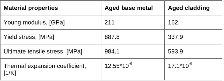
The material properties can be seen in the Table1. Poisson’s ratio ν=0.3 was used in all cases. The residual
stress was also considered during the analyses.
Table 1.: Material properties of the specimens
Material properties Aged base metal Aged cladding
Young modulus, [GPa] 211 162
Yield stress, [MPa] 887.8 337.9
Ultimate tensile stress, [MPa] 984.1 593.9
Thermal expansion coefficient, [1/K]
4
SPECIMEN GEOMETRY
4PB specimen geometry was discretized and used in the finite element analyses. Two different crack front positions were analyzed, and three specimens were modelled by FEM (two short cracks and a longer one). The specimen geometry and one of the meshed models can be seen in the Fig. 1. 20 nodes hexahedron elements were applied for generating 3D FE models of specimens. Symmetry conditions were applied in the model.
Support(Reaction Force F/2)
670 mm
(Total)Applied Force F Flaw Centreplane
248 mm 57 mm
Support(Reaction Force F/2)
Figure 1. Specimen geometry and the meshed 3D finite element model
5
RESIDUAL STRESS
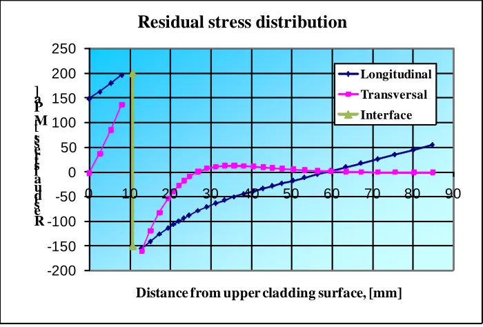
Residual stress was considered in the analyses based on the stress free temperature method. This means that residuals stress arises from difference of the thermal expansion coefficients. Stress free temperature:
T=350°C. Thermal expansion coefficient for base metal was 12.55*10-6 and for the cladding was 17.1*10-6.
The longitudinal and transversal component of residual stress can be seen in the Fig. 2.
-200 -150 -100 -50 0 50 100 150 200 250
0 10 20 30 40 50 60 70 80 90
R es id u a l s tr es s, [ M P a ]
Distance from upper cladding surface, [mm]
Residual stress distribution
Longitudinal
Transversal
Interface
Figure 2. Residual stress distribution calculated by BZF
1E2
0 50 100 150 200 250 300
0 1 2 3 4
Displacement, [mm]
Force, [kN]
FEM result_BZF Measurement_NRI
1E4
0 50 100 150 200 250 300 350 400
0 2 4 6
Displacement, [mm]
Force,
[kN]
FEM result_BZF Measurement_NRI
1E7
0 50 100 150 200 250
0 1 2 3 4
Displacement, [mm]
Force,
[kN]
FEM result_BZF Measurement_NRI
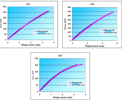
Figure 3. Validation of LLD curves of certain specimens
6
J-INTEGRAL CALCULATION
The effect of crack front position was studied in this work for all specimens. In the J-integral calculation the significant effect of the cladding interface had to be taken into account at the upper crack tips. As the upper crack tips are very close to the fusion line of the cladding in all cases, it is not so easy to study the crack size effect. So it was decided, that upper crack front has been moved down first in two steps, then moved up in one step.
0 50 100 150 200 250 300 350
-2 -1 0 1 2 3 4 5
Distrance fom the crack tip, [mm] Upper crack front moving, 1E2 specimen
Calculated J
linear extr
2nd order
3rd order
Figure 4. Extrapolation to the interface
6.1 J-integral calculation close to the interface
The J-integral is path independent if the integration path is out of the plastic zone that occurs around the crack tip and the path does not cross any other discontinuity such as the bimetallic interface. If the crack tip is close to the interface, it can be a problem to find a proper path that does not cross the interface. In this case the total integral has to be separated into two parts, one caused by the crack as a primary discontinuity and the other one caused by the bimetallic interface as a secondary discontinuity:
F
C
J
J
J
#=
"1=
"2!
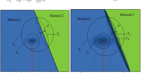
(1)where CΓI is J like integral around the section of the interface that had been cut out as by Γ2 it shows the Fig.
5a. CΓI is independent from the „d” thickness of the ΓI if the deformation around the fusion line are linear
elastic. If plastic deformation occurs around the interface CΓI is strongly dependent from the „d” thickness
and can be calculate as the follows:
I M
F M F F
C C
C C
d" ! !
!
For calculation of CΓF based on FEM results there are two ways:
„Exact” CΓF calculation by path integral:
• This way gives the most reliable result, but
• Not supported directly by FEM software (usually)
• Stress and strain data should be post-processed
• Additional external calculation program needed
CΓF calculation by virtual crack extension method:
• It is based on domain integration
• „d” cannot be equal 0
• Smooth mesh is needed perpendicular to the fusion line
• At least 3 domain integral is needed for convergent result
• crack tip must be out of the ΓI
• It can be done by commercial FEM codes without external programs (Excel is useful)
Since in our case only a few calculations were needed the second way has been applied. In FEM representation of the J-integral calculation the path integral is transformed to domain integral and calculated by virtual crack extension method.
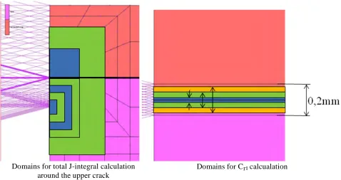
At first, for validation, the method has been applied for the original upper crack tip. The domains that have been defined can be seen on Fig. 6.
Domains for total J-integral calculation around the upper crack
Domains for CΓI calcualation
Figure 6. Integration domains for J and CΓF calculation by virtual crack extension method
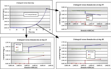
The results of the calculation can be seen on the Fig. 7 and it can be concluded that the J-integral values calculated on the domains including the interface are really path independent when CΓF has been taken off
Figure 7. Path independent J after taking off CΓF
6.2 J calculation when crack tip is on the interface
Since the method applicable only when crack tip out of the ΓI, J-integral has to be calculated both side of the
fusion line. On the other hand determination of J-integral on the interface is still a theoretical question since it has discontinuity there as well. For the calculation two crack tips have been defined only 0,137 mm far from interface at both sides. It is pretty close to be able to make conclusion to the interface. As before J and
CΓF calculation have been done by virtual crack extension method. For the interface CΓF has been calculated
by interpolation.
0,137mm
0,137mm
Figure 8. Crack tip and mesh at both side
-4,00E+04 -2,00E+04 0,00E+00 2,00E+04 4,00E+04 6,00E+04 8,00E+04
0,00E+00 2,00E-03 4,00E-03 6,00E-03 8,00E-03 1,00E-02
J -i n te g r a l, [ J /m 2 ]
domain width [m]
J-integral versus domain size at step 55
J-total C J 0,00E+00 2,50E+03 5,00E+03 7,50E+03 1,00E+04 1,25E+04 1,50E+04 1,75E+04
0,00E+00 2,00E-03 4,00E-03 6,00E-03 8,00E-03 1,00E-02
J -i n te g r a l, [ J /m 2 ]
domain width [m]
J-integral versus domain size at step 40
J-total C J 0,00E+00 2,50E+03 5,00E+03 7,50E+03 1,00E+04 1,25E+04
0,00E+00 2,00E-03 4,00E-03 6,00E-03 8,00E-03 1,00E-02
J -i n te g r a l, [ J /m 2 ]
domain width [m]
J-integral versus domain size at step 25
J total C J 0,00E+00 1,00E+04 2,00E+04 3,00E+04 4,00E+04 5,00E+04 6,00E+04 7,00E+04
0 10 20 30 40 50 60
J -i n te g r a l, [ J /m 2 ] Time step J-integral versus time-step
-3,00E+05 -2,00E+05 -1,00E+05 0,00E+00 1,00E+05 2,00E+05 3,00E+05 4,00E+05 5,00E+05
1,00E-04 1,00E-03 1,00E-02 1,00E-01 1,00E+00
J -i n te g ra l, [ J /m 2 ]
domain width [m]
J-integral for crack at at the interface
J total C interpolated J -2,00E+05 -1,50E+05 -1,00E+05 -5,00E+04 0,00E+00 5,00E+04 1,00E+05 1,50E+05 2,00E+05 2,50E+05 3,00E+05 3,50E+05
1,00E-04 1,00E-03 1,00E-02 1,00E-01 1,00E+00
J -i n te g ra l, [ J /m 2 ]
domain width [m]
J-integral for crack tip above the interface
J total C J -4,00E+05 -3,00E+05 -2,00E+05 -1,00E+05 0,00E+00 1,00E+05 2,00E+05 3,00E+05 4,00E+05 5,00E+05
1,00E-04 1,00E-03 1,00E-02 1,00E-01 1,00E+00
J -i n te g ra l, [ J /m 2 ]
domain width [m]
J-integral for crack tip under the interface
J total C J
Figure 9. Integral values versus domain with close to the interface
The results can be plot together with the previously calculated J-integral values for under clad crack (Fig.
10.). It can be see that the extrapolation based on 3rd order approximation gives much lower values than the
value determined by the applied method. At the interface there is a significant drop in J due to the different CΓF. However the J-integral value have been plotted as well it is no more than an average value since CΓF has
discontinuity at the interface.
0 50 100 150 200 250 300 350 400 450 500
-6 -5 -4 -3 -2 -1 0 1 2
J -i n te g r a l, [ k J /m 2 ]
Distrance from the interface, [mm] J-intergral, 1E2 specimen
crack tip at interface
crack tip up to the interface
crack tip above the interface
linear extrapolation
7
CONCLUSIONS
J-integral calculation was performed to study the effect of crack size in case of sub-clad flaws. Elastic-plastic material properties were applied, and the residual stresses were considered during the analysis. The effect of modified crack fronts was analyzed. ΔJ/Δa have shown that the J-integral at upper crack front is sensitive for the crack tip position and conclusion cannot be drown to the interface, so virtual crack extension method has been extend to the cases when the integration domain contains secondary discontinuity. The proposed new method has been verified and the J-integral values for the situation when the crack tip is “on” the interface have been determined with the proposed new method. The calculation results show that the J-integral has a significant discontinuity at the interface that has to be taken into consideration at the fracture mechanical evaluation.
Acknowledgements. The authors would like to acknowledge the support of the NESC -IV project participants and in particular to NRI and JRC.
REFERENCES
Large scale cladded beam specimen tests, Description of the project for NESC, Nuclear Research Institute Rez plc, Divison of Integrity and Technical Engineering, Rez, September 2006.