ISSN(Online): 2319-8753 ISSN (Print): 2347-6710
I
nternational
J
ournal of
I
nnovative
R
esearch in
S
cience,
E
ngineering and
T
echnology
(An ISO 3297: 2007 Certified Organization)
Website: www.ijirset.com
Vol. 6, Issue 7, July 2017
Reduction of Harmonics by Multipulse
Method of Diode and Thyristor Rectifier
Neha1, Nisha2
M.Tech Student, Dept. of ECE, OITM, Guru Jambheshver University, Hisar, Haryanaz, India¹,2
ABSTRACT: Now days the problem of power excellence is a main concerned area of research in the power region. Now it is possible to keep power region free from contamination with the development in the technology. Total
Harmonic Distortion using different concepts and applications. Last few years Filtering and Cancellation method used
for harmonic treatment. Now we contract with the reduction of Total Harmonic Distortion using Multi-pulse AC to DC Conversion scheme. In this paper power quality can be improved with multi pulse converter, 6, 12, 18, 24, 30, 36, 48 pulse converters have been modeled and simulated in MATLAB/SIMULINK software. For proper AC to DC conversion, we make more set of 6- pulse systems, a uniform phase shift is required with proper phase-shifting angle, 12, 18, 24, 30, and higher pulse systems have been created. The presentation improvement of multipulse converter is achieved for total harmonics distortion (THD) in supply current.
KEYWORDS: Multi-pulse method, Total harmonic reduction (THD), Power factor, Input current, diode, register, rectifier
I. INTRODUCTION
The increasing use of Non-linear loads like Variable Speed Drives, Computers, Electric Furnace, Domestic
Equipments arecontributors to Harmonic problems. Distorted power can come in the form of short-termtransients or
steady state continuous distortions. Harmonics are sinusoidal voltages or currents having frequencies that are integer
multiples of the frequency at which the supply system is designed to operate (termed the fundamentalfrequency usually
50 Hz or 60 Hz) harmonics combine with the fundamental voltage or current, and produce waveform distortion. Harmonic distortion exists due to the nonlinear characteristics of devices and loads on the power system. These devices
can usually be modeled as current sources that inject harmonic currents into the power system. Voltage distortion
results in these currents cause nonlinear voltage drops across the system impedance. Harmonics are a steady-state phenomenon, unlike transients. The level of harmonic distortions (either voltage or current) that exist at any point of a power system is expressed as Total Harmonic Distortion (THD). Harmonic Distortion can cause serious operating problems including resonance under certain electrical environments. Transformers, motors and other inductive loads are particulary affected since they are designed to operate at the fundamental frequency.
1.1 Symptoms of Harmonic Distortion
1. If the current at the plants, power factor correcting capacitor exceeds 5% of input voltage, the presence of voltage
harmonic distortion is there
2. Check for the neutral to ground voltage and if it exceeds 2 volts, an indication of possible 3rd harmonics problems.
3. Check the pattern of KVA data of all non-linear loads. If its total is just about 10-15% of voltage then ordinary pf
Figure 1: Harmonic Reduction Technique
II. LITERATURE SURVEY
Kaplon A, Rolekknk K, Tunja H Discussed about the rectifiers consisting of parallel connected 6-pulse bridges with modulation in DC current circuit show properties of multipulse rectifiers. A load unbalance of the component bridges of 12-pulse rectifier approximates the space vector to the case of rotating one. In consequence the shape of the line currents is close to sinusoidal one. In this paper the topology of multi-pulse rectifier with modulation in DC current circuit is presented. The simulation results of investigations were obtained by means of the space vector for control of modulators. The laboratory results of investigations of 2 kvass power for 12 - and multi-pulse inverters have been presented
III. PROPOSED METHODOLOGY AND DISCUSSION
ISSN(Online): 2319-8753 ISSN (Print): 2347-6710
I
nternational
J
ournal of
I
nnovative
R
esearch in
S
cience,
E
ngineering and
T
echnology
(An ISO 3297: 2007 Certified Organization)
Website: www.ijirset.com
Vol. 6, Issue 7, July 2017
Figure3: THD For input current
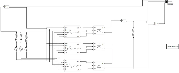
18-pulse thyristor rectifier: For modeling of 18 pulse thyristor multi-pulse rectifier three combinations of zig-zag phase shift transformer and thyristor bridge are required for reducing the harmonic contents in input current. A synchronized 18 pulse generator is required to feed the input pulse to thyristor bridge. A trigger pulse given to thyristor through 6 pulse synchronized generator to start thyristor.
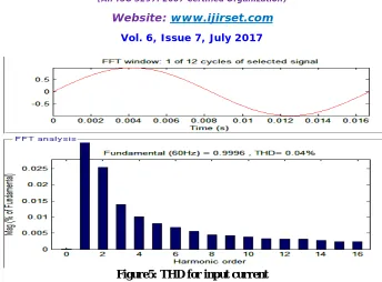
Figure5: THD for input current
IV. EXPERIMENTAL RESULTS WITH TABLES
For 18-pulse diode rectifier
Fundamental frequency = 60 Hz
Max. Harmonic frequency used for THD Calculation = 2509860.00 Hz (41831th harmonic) Total Harmonic Distortion = 0.01
Harmonic Order Respective THD
5 (300 hz) 0.00
7 (420 hz) 0.00
9 (540 hz) 0.00
11 (660 hz) 0.00
13 (780 hz) 0.00
15 (900 hz) 0.00
ISSN(Online): 2319-8753 ISSN (Print): 2347-6710
I
nternational
J
ournal of
I
nnovative
R
esearch in
S
cience,
E
ngineering and
T
echnology
(An ISO 3297: 2007 Certified Organization)
Website: www.ijirset.com
Vol. 6, Issue 7, July 2017
Harmonic Order Respective THD
5 (300 hz) 0.01
7 (420 hz) 0.01
9 (540 hz) 0.00
11 (660 hz) 0.00
13 (780 hz) 0.00
15 (900 hz) 0.00
Table no.1.2 THD for 18-pulse thyristor rectifier
IV. CONCLUSION
This thesis work specifies the MATLAB/SIMULATION model. Comparison of performances of 6 pulse 12 pulse 18 pulse 24 pulse 30 pulse 36 pulse 42 pulse 48 pulse is done. Best result of harmonics reduction and regulated output
voltage is obtained usingmulti-pulse rectifier. As the number of pulses increase harmonic reduction will be better and
hence a better DC link output voltage is achieved.
REFERENCES
[1] Shashikant R, Raval H, Bhavans N, “Mitigation of Harmonics In A.C Drive by using Multi-Pulse Transformer Solution”, Journal of Information, Knowledge and Research in Electrical Engineering, 2012.
[2] Jain R, Singh D, Jain M, “Supply Current Harmonics Control using Multipulse Rectifiers”, 2013.