Design of DC-DC Converter for MFC
Application on MAV
Radhika S Nadiger1, Siva Subba .Rao Patange2, Aravindu B3, Mahommed Toufiq A Hindustani4
P.G. Student, The National Institute of Engineering, Mysuru, Karnataka, India1
Principal Scientist, CSIR-National Aerospace Laboratories, Bengaluru, India2
Senior Technical Officer, CSIR-National Aerospace Laboratories, Bengaluru, India3
Project Graduate Trainee, CSIR-National Aerospace Laboratories, Bengaluru, India4
ABSTRACT:This paper presents the design of DC-DC converter operating from -500V to +1500V DC for the
actuation of Macro Fiber Composites (MFC) used onMicro Aerial Vehicles (MAV). The MFCrequires high voltage for ample displacement. The main focus is to design a suitable power electronic circuit for powering the MFC. For successful and effective flight of modern MAV, MFC is used for control surface deflection. As the control actuator, servo mechanism are still and brittle and are not suitable for morphing applications that involves large deformations, hence MFC’s are used. Therefore a DC-DC converteris designed such that it has less weight and gives high voltage output i.e. -500V to +1500V using a modified flyback converter,drawing power from low voltage sources, such as on board batteries.Compact size and a high conversion ratio are needed in low-voltage input and high voltage output applications. PWM signals are used for proper control of the switches to obtain the desired output voltage.The designed DC-DC converter circuit is simulated in MATLAB/SIMULINK.
KEYWORDS:Micro Aerial Vehicles (MAV), Macro Fiber Composites (MFC), DC-DC Converter, PWM,
MATLAB/SIMULINK.
I.INTRODUCTION
The power converter plays an important role in the industrial and consumer products in their suitable applications. The circuit efficiency, least profile, safety, duty ratio, power level and preference of the active and passive components strengthen the competency for the degree of different applications. The topology selection [1] criteria of the power converter are based on the application regions of electrical isolation, operating mode and duty cycle as technical aspects.The design of DC–DC converters with high efficiency especially in the range of 75–90% is a challenging task [2, 3]. The DC–DC converters designed for MFC applications should have high-voltage gain and should operate at high efficiency.
II.DESIGNOFHIGHVOLTAGEDC-DCCONVERTERS
The DC–DC converter design is optimised to satisfy the contradictory constraints such as low production cost and high reliability. Also, in many DC power applications, electrical isolation is required between input and output sides of the DC-DC converter, so that the loading device is protected from input transients and the ground loops resulting from the common return paths between different parts of the electronic circuitries are eliminated.
The flyback and forward DC–DC converters are the most popular choices for low-power DC applications that require such electrical isolation. In both flyback and forward converters, the input to output electrical isolation is provided by a high-frequency (HF) transformer. The forward converter requires an additional winding so that the residual magnetic flux in the HF transformer core is reset. Therefore, flyback converters are generally preferred over forward converters for low-voltage DC applications since the former is simpler, easier to design, less expensive and has lesser magnetic components than the latter. Flyback converters also operate over a wide range of input voltages and use a single switch to provide multiple regulated output voltages [6-8]. Fly-back converter is the most commonly used in SMPS circuit for low output power applications where the output voltage needs to be isolated from the input main supply. The output power of fly-back type may vary from few watts to less than 100watts. The commonly used flyback converter requires a single controllable switch like, MOSFET and the usual switching frequency is in the range of 100 kHz.
Figure.1: Basic DC-DC Converter Circuit
Design Parameters
The design parameters of DC-DC converter for the operation of MFC application are shown in Table 1
TABLE 1: Design Parameters
Input Voltage 12V DC
Output Voltage 1.Fixed Output Voltage: -500V DC
2.Variable Output Voltage range: 0V to 1500V
Control Signal PWM Signal range: 20% to 80%
III.SIMULINKIMPLEMENTATION
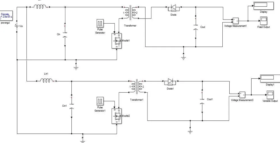
Simulink is a software package for modelling, simulating and analysing dynamical systems. The simulation of the modified flyback converter for the given parameters is implemented in MATLAB/SIMULINK. The circuit design implementation of modified flyback converter which is simulated is shown infigure 2.
Figure.2: Modified Flyback Converter
The design contains two flyback converters with one input source, voltage measurement, display, scope. The commonly used flyback converter requires a single controllable switch like MOSFET and the operating switching frequency is in the range of 10 kHz.The input to designed circuit is powered from a 12V DC source, which is usually from on board battery or a solar photovoltaic source. The two converters are connected in parallel to the same input and operate simultaneously as follows:
Mode 1: Fixed Output Voltage
charged. A negative voltage is achieved by reversing the diode. Thus a fixed output voltage of -500V DC is obtained at the channel 1.
Mode 2: Variable Output Voltage
In order to obtain a variable positive output voltage, the second converter operates in a similar manner to that of first converter with the only difference that the diode is not reversed. When the duty cycle is varied from 20% to 80% a variable output voltage in the range of 0V to +1500V DC is obtained respectively.
IV. RESULTS
The simulation results for the Mode 1 and Mode 2 operations are shown below:
Mode1: Fixed output voltage
For an input voltage of 12V DC a fixed output voltage of -506V DC is obtained as shown in the figure.3.
Figure.3: Simulation output of -500V DC fixed output voltage
Mode 2:Variable Output Voltage
Case 1:An output voltage of 311V DC is obtained for 20% PWM with 12V DC inputand the simulation output is shown in figure.4.
Figure.4: Simulation output for 20% PWM Input
Figure.5: Simulation output for 40% PWM Input
Case 3:An output voltage of 786.4V DC is obtained for 60% PWM with 12V DC inputand the simulation output is
shown infigure.6.
Figure.6: Simulation output for 60% PWM Input
Case 4:An output voltage of 1353V DC is obtained for 80% PWM with 12V DC input and the simulation output is
shown infigure.7.
Figure.7: Simulation output for 80% PWM Input
V.CONCLUSION
from 0V to +1500V DC to control the operation of MFCs. The entire circuit is simulated using SIMULINK. A fixed output voltage of -506V DC is obtained as shown in the figure 8. and a variable output voltage of +311V DC to +1353V DC for 10% to 80% PWM input respectively is shown in the figure9. The obtained output voltage is sufficient to drive the MFC.
Figure.8: Fixed output voltage
Figure.9: Variable output voltage
ACKNOWLEDGEMENT
The authors would like to thank the Director, MrJitendra J Jadhav, CSIR-National Aerospace Laboratories for his persistence to carry out the work and Dr.Satish Chandra, Head Structural Technologies Division (STTD) for providing all the facilities for completing this work and Dr. S. Raja, Group Head of STTD for supporting and inspiring to complete the work. My Special thanks to MrRaghavendra and MsSowmia, Structural Technologies Division (STTD), CSIR-National Aerospace Laboratories, for their help.
REFERENCES
[1] T. Halder, “A Topology selection: An Isolated Flyback converter”, 978-1-4673-8962/16$31.00©2016 IEEE.
[2] Woo Young, C., “High-efficiency DC–DC converter with fast dynamic response for low-voltage photovoltaic sources”, IEEE Trans. Power Electron., 2013, 28, (2), pp. 706–716
[3] Fatih, E., Mehmet Timur, A.: “Z-source-based isolated high step-up converter”, IET Power Electron., 2013, 6, (1), pp. 117–124 [4] “Macro-Fiber Composite (MFC) Actuator” by NASA, Patent No: 6,629,341; 7,197,798.
[5] M. Karpelson, G. Y. Wei and R. J. Wood, “Milligram-Scale High-Voltage Power Electronics for Piezoelectric Micro Robots”, IEEE Conference on Robotics and Automation, May 12-17,2009,pp. 2217-222
[6] Federico Martin, I., Jose Martin, E., Daniel, A, “Soft-switching forward DC– DC converter using a continuous current mode for electric vehicle applications”, IET Power Electron., 2015, 8, (10), pp. 1978–1986
[7] Zhang, J., Huang, X., Wu, X., “A high efficiency flyback converter with new active clamp technique”, IEEE Trans. Power Electron., 2010, 25, (7), pp. 1775– 1785