Brushless DC Motor Drive Based On Fuzzy
Logic Controller for Solar PV Fed Water
Pumping System Using Zeta Converter
Y.Shiva Jyothi 1, T.Pardhavi Sai Sree 2
M.Tech, Dept. of Electrical & Electronic Engineering, Sri Padmavathi mahila visvavidyalayam
Tirupathi, A.P. India1
Assistant Professor, M.Tech, Dept. of Electrical & Electronics Engineering, Sri Padmavathi mahila visvavidyalayam
Tirupathi, A.P, India2
ABSTRACT: This paper proposes a basic, cost effective and effective brushless DC (BLDC) motor drive for sun based photovoltaic (SPV) cluster encouraged water pumping system. A zeta converter is used with a specific end goal to separate the greatest accessible power from the SPV array. The proposed control calculation dispenses with stage current sensors and adjusts an essential recurrence switching of the voltage source inverter (VSI), in this manner keeping away from the power losses because of high recurrence switching. No extra control or hardware is utilized for speed control of the BLDC motor. The speed is controlled through a variable DC connect voltage of VSI. A fitting control of zeta converter through the incremental conductance greatest power point following (INC-MPPT) calculation offers delicate beginning of the BLDC motor. The proposed water pumping system is planned and demonstrated with the end goal that the execution is not influenced under element conditions. This paper consists digital implementation of a fuzzy controller for achieving improved performance of Brushless dc (BLDC) servomotor drive. The performance of fuzzy and PI controller-based BLDC servomotor drives is investigated under different operating conditions such as change in reference speed, parameter variations, load disturbance.
KEYWORDS: BLDC motor, SPV array, Water pump, Zeta converter, VSI, INC-MPPT,Fuzzy Controller.
I. INTRODUCTION
The extreme decrease in the cost of power electronic devices and destruction of fossil fuels in not so distant future welcome to utilize the sun based photovoltaic (SPV) created electrical vitality for different applications quite far. The water pumping, an independent use of the SPV cluster produced power is accepting wide consideration now a days for water system in the fields, family unit applications and mechanical utilize. Albeit a few inquires about have been completed in a territory of SPV cluster sustained water pumping, joining different DC-DC converters and motor drives, the zeta converter in relationship with a changeless magnet brushless DC (BLDC) motor is not investigated exactly so far to grow such sort of system. Be that as it may, the zeta converter has been utilized as a part of some other SPV based applications[1] besides topology of SPV array encouraged BLDC motor driven water pump with zeta converter has been accounted for and its noteworthiness has been introduced pretty much in[2] in any case, an exploratory approval is missing and the nonattendance of broad writing survey and correlation with the current topologies, have disguised the specialized commitment and inventiveness of the revealed work.
• Belonging to group of buck-boost converters [5] zeta converter might be worked either to increase or to decrease the output voltage. This property offers a limitless area for maximum power point tracking (MPPT) [6]of a SPV array. The MPPT can be performed with straightforward buck and help converter if MPP happens inside endorsed limits.
• This property likewise encourages the delicate beginning of BLDC motor not at all like a boost converter which constantly ventures up the voltage level at its output, not guaranteeing delicate beginning.
• Unlike an established buck-boost converter, the zeta converter has a nonstop output current. The output inductor makes the current persistent and swell free.
• Although comprising of same number of parts as a Cuk converter, the zeta converter works as non-modifying buck-boost converter not at all like a rearranging buck-boost and Cuk converter. This property forestalls a necessity of related circuits for negative voltage detecting consequently lessens the multifaceted nature and likelihood of back off the system reaction.
These benefits of the zeta converter are positive for proposed SPV cluster encouraged water pumping system. An incremental conductance (INC) MPPT calculation is utilized to work the zeta converter with the end goal that SPV array dependably works at its MPP.
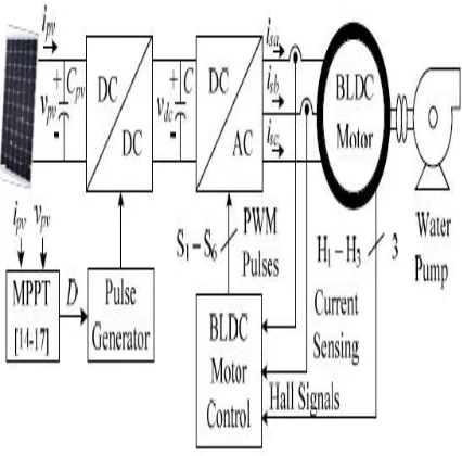
The existing literature investigating SPV array based BLDC motor driven water pump [7] depends on an arrangement appeared in Fig. 1. A DC-DC converter is utilized for MPPT of a SPV array as usual. Two phase currents are detected alongside Hall signals feedback for control of BLDC motor, bringing about an expanded cost. The extra control plot causes expanded cost and complexity, which is required to control the speed of BLDC motor. In addition, for the most part a voltage source inverter (VSI) is worked with high frequency PWM pulses, bringing about expanded switching losses and consequently the diminished effectiveness. In any case, a Z-source inverter (ZSI) replaces DC-DC converter in, other schematic of Fig. 1 staying unaltered, promising high proficiency and ease. As opposed to it, ZSI likewise requires phase current and DC link voltage detecting bringing about the unpredictable control and expanded cost.
Fig. 1 Conventional SPV fed BLDC motor driven water pumping system.
forward and efficient system without scarifying its execution. The speed of BLDC motor is controlled, with no extra control, through a variable DC link voltage of VSI. Besides, a delicate beginning of BLDC motor is accomplished by appropriate introduction of MPPT calculation of SPV cluster. These elements offer an expanded effortlessness of propose.
Fig.2.Proposed solar PV-zeta converter fed BLDC motor drive for water pump.
The advantages and desirable features of both zeta converter and BLDC motor drive add to build up a basic, productive, practical and solid water pumping system in light of sun based PV energy. Simulation results utilizing MATLAB/Simulink and test arrayions are analyzed to show he beginning, flow and relentless state conduct of proposed water pumping system subjected to pragmatic working conditions. The SPV cluster and BLDC motor are outlined to such an extent that proposed system dependably displays great execution paying little respect to sun powered irradiance level.
II. CONFIGURATION OF PROPOSED SYSTEM
The structure of proposed SPV array nourished BLDC motor driven water pumping system utilizing a zeta converter is appeared in Fig. 2. The proposed system comprises of (left to right) a SPV array, a zeta converter, a VSI, a BLDC motor and a water pump. The BLDC motor has an inbuilt encoder. The pulse generator is utilized to work the zeta converter. A well ordered operation of proposed system is explained in the accompanying section in detail.
III. OPERATION OF PROPOSED SYSTEM
The SPV array produces the electrical power requested by the motor pump. This electrical power is nourished to the motor pump by means of a zeta converter and a VSI. The SPV array shows up as a power source for the zeta converter as appeared in Fig. 2. Preferably, a similar measure of power is exchanged at the yield of zeta converter which shows up as an information hotspot for the VSI. Practically speaking, because of the different losses related with a DC-DC converter, somewhat less measure of influence is exchanged to encourage the VSI. The pulse generator produces, through INC-MPPT calculation, switching beats for IGBT (Insulated Gate Bipolar Transistor) switch of the zeta converter. The INC-MPPT calculation utilizes voltage and present as criticism from SPV array and creates an ideal estimation of obligation cycle. Advance, it produces genuine switching pulse by contrasting the duty cycle and a high frequency carrier wave. Along these lines, the greatest power extraction and subsequently the effectiveness improvement of the SPV array is refined.
motor helped by its implicit encoder. The high frequency switching losses are consequently disposed of, contributing in an expanded effectiveness of proposed water pumping system.
IV. DESIGN OF PROPOSED SYSTEM
Different working stages appeared in Fig 2, are appropriately outlined so as to build up a successful water pumping system, fit for working under unverifiable conditions. A BLDC motor of 2.89 kW control rating and a SPV array of 3.4 kW crest control limit under standard test conditions (STC) are chosen to outline the proposed system. The definite outline of different stages, for example, SPV array, zeta converter and water pump are depicted as takes after.
A. Design of SPV Array
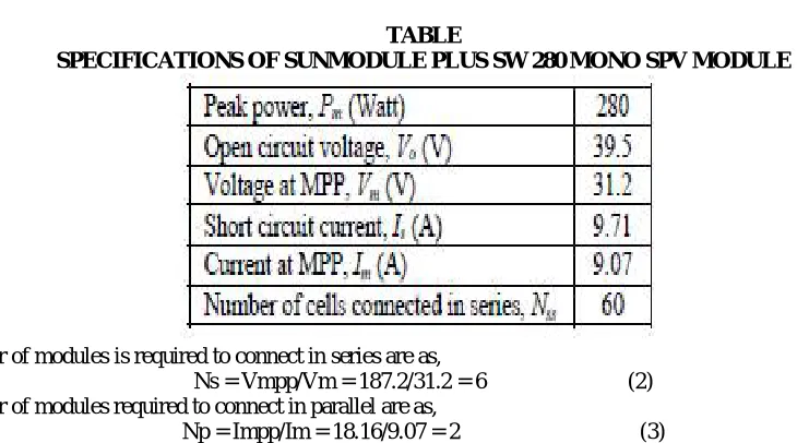
According to above discussion, the commonsense converters are related with different power loss moreover, the execution of BLDC motor pump is affected by related mechanical and electrical losses. To remunerate these losses, he size of SV array is chosen with somewhat more pinnacle influence ability to guarantee the palatable operation paying little heed to influence losses. Hence, the SPV array of peak power capacity of Pmpp = 3.4 kW under (STC: 1000W/m², 25°C, AM 1.5), marginally more than requested by the motor pump is chosen and its parameters are planned as needs be. Solar World make Sun module Plus SW 280 mono SPV module is chosen to plan the SPV array of a proper size. Electrical particulars of this module are recorded in Table I and quantities of modules required to interface in arrangement/parallel are assessed by choosing the voltage of SPV array at MPP under STC as, Vmpp = 187.2 V.
The current of SPV array at MPP, Impp is estimated as,
Impp = Pmpp/Vmpp = 3400/187.2 = 18.16 A (1)
TABLE
SPECIFICATIONS OF SUNMODULE PLUS SW 280 MONO SPV MODULE
The number of modules is required to connect in series are as,
Ns = Vmpp/Vm = 187.2/31.2 = 6 (2) The number of modules required to connect in parallel are as,
Np = Impp/Im = 18.16/9.07 = 2 (3)
Connecting 6 modules in series, having 2 strings in parallel, a SPV array of required size is designed for the proposed system and its data are given in Appendix A.
B. Design of Zeta Converter
The zeta converter is the following phase of SPV array . its outline comprises of an estimation of different segments, for example, input inductor, L1, yield inductor, L2 and middle of the road capacitor, C1. These segments are outlined to such an extent that the zeta converter dependably works in CCM bringing about decreased weight on its segments and devices. An estimation of the obligation cycle, D starts the plan of zeta converter which is assessed as,
(4)
An average current flowing through the DC link of the VSI, Idc is estimated as, Idc = Pmpp/Vdc = 3400/200 = 17 A (5) Then L1, L2 and C1 are estimated as ,
Where fsw switching frequency of IGBT switch of the zeta converter ∆ IL1 is the measure of allowed swell in current
flowing through L1, same as IL1 = Impp; ΔIL2 is the measure of allowed swell in the present moving through L2, same as IL2 = Idc; ΔVC1 is allowed swell in the voltage crosswise over C1, same as VC1 = Vdc. Point by point information
of the zeta converter are given in Appendix B.
C. Estimation of DC Link Capacitor of VSI
Another plan approach for estimation of DC connection capacitor of the VSI is arrayed here. This approach depends on a reality that sixth consonant segment of the supply (AC) voltage is pondered the DC side as a predominant symphonious in the three stage supply system. Here, the crucial frequencies of yield voltage of the VSI are evaluated comparing to the appraised speed and the base speed of BLDC motor basically required to pump the water. These two frequencies are further used to assess the estimations of their relating capacitors. Out of these two evaluated capacitors, bigger one is chosen to guarantee a tasteful operation of proposed system even under the base sun powered irradiance level. The major yield recurrence of VSI relating to the appraised speed of BLDC motor, ω rated is assessed as,
The fundamental output frequency of the VSI corresponding of the minimum speed of the BLDC motor essentially required to pump water(N=1100 rpm), ω min is estimated as,
where f rated and f min are fundamental frequencies of output voltage of VSI corresponding to a rated speed and a minimum speed of BLDC motor essentially required to pump the water respectively, in Hz; N rated is rated speed of the BLDC motor; P is a number of poles in the BLDC motor. The value of DC link capacitor of VSI at ω rated is as,
D. Design of Water Pump
To estimate the proportionality constant, K for the selected water pump, its power-speed characteristics is used as,
Where P=2.89 kW is appraised control created by the BLDC motor and ωr is evaluated mechanical speed of the rotor
(3000 rpm) in rad/sec.
A water pump with this information is chosen for proposed system.
E. Design Fuzzy logic Controller
Fuzzy logic is a form of many-valued logic in which the truth values of variables may be any real number between 0 and 1. By contrast, in Boolean logic, the truth values of variables may only be 0 or 1. Fuzzy logic has been extended to handle the concept of partial truth, where the truth value may range between completely true and completely false. Furthermore, when linguistic variables are used, these degrees may be managed by specific functions.
Usually fuzzy logic control system is created from four major elements presented on Figure fuzzification interface, fuzzy inference engine[12] fuzzy rule matrix and defuzzification interface. Each part along with basic fuzzy logic operations will be described in more detail below.
1. The fuzzy logic analysis and control methods shown in Figure 1 can be described as: Receiving one or large number of measurements or other assessment of conditions existing in some system that will be analyzed or controlled.
2. Processing all received inputs according to human based, fuzzy ”if-then” rules, which can be expressed in simple language words, and combined with traditional non-fuzzy processing.
3. Averaging and weighting the results from all the individual rules into one single output decision or signal which decides what to do or tells a controlled system what to do. The result output signal is a precise defuzzified value.
V. CONTROL OF PROPOSED SYSTEM
The proposed is controlled in two stages. These two control techniques, viz. MPPT and electronic commutation are discussed as follows.
A.INC-MPPT Algorithm
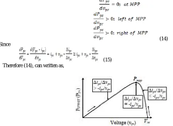
view of the incline of Ppv-vpv bend appeared in Fig. 3. As appeared in Fig. 3, the slant is zero at MPP, positive on the left and negative on the privilege of MPP, i.e.
(14) Since
(15)
Therefore (14), can written as,
Fig .3 illustration of INC_MPPT with SPV array Ppv-Vpv characteristics.
(16)
Consequently, in view of the connection between incremental conductance and immediate conductance, the controller chooses the bearing of bother as appeared in fig,3. also, expands/reductions of the obligation cycle as needs be. For example, on the privilege of MPP, the obligation cycle is expanded with the settled bother measure until the bearing turns around. In a perfect world, the annoyance stops once the working point comes to the MPP. Be that as it may, practically speaking, working point sways around the MPP.
As the annoyance estimate lessens, the controller sets aside greater opportunity to track the MPP of SPV array. A scholarly assention between the following time and the bother size is held to satisfy the goals of MPPT and delicate beginning of BLDC motor. So as to accomplish delicate beginning, the underlying estimation of obligation cycle is set as zero. Furthermore, an ideal estimation of bother size (∆D=0.001) is chosen, which adds to delicate beginning and
furthermore limits motions around the MPP.
A specific blend of Hall-impact signs is delivered for every particular scope of rotor position at an interim of 60° . The generation of six switching states with the estimation of rotor position is arranged in Table II. It is detectable that lone two switches lead at once, bringing about 120º conduction method of operation of VSI and thus the decreased conduction losses. Other than this, the electronic replacement gives basic recurrence switching of the VSI, consequently losses related with high recurrence PWM switching are disposed of. TETRA 115TR9.2, In this paper, de- sign and implementation of fuzzy controller is presented and its performance is compared with PID controller to show its capable to track the error and usefulness of fuzzy controller in control applications.
Simulation Results
Case1: BLDC_Solar_ZetaConverter_costant_irradiation
Irradiance
PV Power
PV Voltage
IL1
VC1
IL2
VSW
Vd
Id
Vdc
Motor phase voltage Ea
Motor Speed
Motor Electromagnetic Torque
Load Torque
Case2: BLDC_Solar_ZetaConverter_Variable_irradiation
PV Power
PV Voltage
PV Current
VC1
IL2
Vdc
Motor Phase Current Ia
Motor Speed
Motor Electromagnetic Torque Te
EXTENSION RESULTS
4. Case1: BLDC_Solar_ZetaConverter_costant_irradiation_Extension
Irradiance
PV Power
PV Voltage
PV Current
VC1
IL2
VSW
ISW
Id
Vdc
Motor phase voltage Ea
Motor stator current Ia
Motor Electromagnetic Torque
Load Torque Case2: BLDC_Solar_ZetaConverter_Variable_irradiation_Extension
Irradiation
PV Voltage
PV Current
IL1
VC1
Vdc
Motor Phase Voltage Ea
Motor Phase Current Ia
Motor Speed
Motor Load Torque TL\
Comparison table of PI controller and FUZZY controller
PI FUZZY
Case-I constant
Ea 45.34% 40.01%
Ia 97.87% 52.27%
Case-II variable
Ea 68.83% 64.99%
Ia 84.59% 50.55%
VII.CONCLUSION
The proposed system has been planned and displayed suitably to fulfill the craved goals and approved to look at the different arrayions under beginning, dynamic and consistent state conditions. The execution assessment has advocated the blend of zeta converter and BLDC motor for SPV array based water pumping. The system under review has indicated different craved capacities, for example, MPP extraction of the SPV array, delicate beginning of BLDC motor, essential recurrence switching of VSI bringing about a lessened switching losses, speed control of BLDC motor with no extra control. And by using fuzzy controller based BLDC motor can provide an improved speed response and easy to design effective in dealing with uncertainities.fuzzy controller based BLDCmotor
May be referred over PI controller based for automation, robotics, industrial applications. `
REFERENCES
[1] S.satapathy, K.M Dash and B.C Babu, “Variable step size MPPT Algorithm for photo voltaic Array Using Zeta Converter-A comparative Analysis” students conference on Engineering and systems (SCES), 12-14 April 2013
[2] Rajan Kumar and Bhim Singh “BLDC Motor Driven solar PV array Fed Water Pumping System Employing Zeta Converter,”in 6th IEEE India
International Conference on Power Electronics (IICPE), 8-10 Dec 2014
[3] B.Singh, V.Bist, A.Chandra and K.Al-Haddad, “Power Factor Correction in Bridgeless-Luo Converter –Fed BLDC Motor Drive,”IEEE Trans.Ind.Appl., vol 51, no.2, pp.1179-1188, March-April 2015.
[4] B.Singh, V.Bist, “Power quality improvement in a zeta converter for BLDC Drives”IET Science,measurement & Technology,vol.9,no.3,pp.351-361
[5] Rajan Kumar and Bhim Singh , “Buck-boost Converter fed BLDC motor drive for Solar PV array based water pumping”IEEE International Conference on Power Electronics,Drives and Energy System (PEDES),16-19 Dec.2014.
[6]M.A.Elgendy, B. Zahawai and D.J. Atkinson “Assesment of the Incremental Conductance Maximum Power Point TrackingAlgoritham,”IEEE Trans.Sustain.Energy, vol.4, no.1, pp.108-117, Jan.2013