An Efficient Maximum Power Point Tracker
for Solar System Using ARM
S.L. Nagare1, S.A. Shaikh2
P.G. Student, Department of Electronics &Telecommunication, Pravara Rural Engineering College, Loni, Maharashtra, India1
Associate Professor, Department of Electronics &Telecommunication, Pravara Rural Engineering College, Loni, Maharashtra, India2
ABSTRACT: It is very important in solar power systems to use the technic of Maximum Power Point Tracking (MPPT) because it does not need the large no. of solar panels to obtain the required output solar energy that means it reduces the cost by using less no. of solar panels. Several different MPPT methods have been proposed, but there has been no comprehensive comparison in between the results obtained by that methods of MPPT algorithms, depending on efficiency and intensity under environmental conditions. This task is performed with the help of Maximum Power Point Tracker(MPPT): it has a function to maximizes the power output of a PV system for environmental conditions of radiation and temperature, thus enhancing the efficiency.
Results are obtained using a “ARM”11 microcontroller on Raspberry pi. The main aim will be to track the maximum power point of the photovoltaic module so that the maximum possible power can be extracted from the photovoltaic. The algorithms utilized for MPPT are generalized algorithms and are easy to model or use as a code. To achieve the Voltage characteristics with respect to time of solar panel and battery as well as when battery will be start charging then after every 2 min. send message on mobile. Also showing the battery charging status still to the charging of Battery is in process. In the present system, starting from the set of whole system of a PV module, an innovative procedure to identify and reach the MPP is presented and experimentally verified.
KEYWORDS: Photovoltaic (PV) cells, Circuit modelling, solar energy, Analysis.
I. INTRODUCTION
The energy obtained from Solar power is a renewable source of energy, which has become progressively more popular in recent times. It has clear advantages over non‐renewable energy sources, such as coal, oil and nuclear energy. It is non‐polluting, consistent and can produce energy anywhere that the area where the sun rays are fallowing down, so its resources are not going to come to an end anytime soon. It even has benefits over other renewable energy sources, such that wind and water power. Solar power is generated using solar panels, which do not require any major mechanical parts, such as wind turbines required for wind energy. These mechanical parts can break and cause repairs issues and can also be quite noisy. Both of these issues are almost non‐existent with solar panels. Also, the solar cells, that connected together to make up the solar panel system, can last up to several periods without replacement.
conversion would be used to provide the accurate power to the system from the power generated by the solar panel. Using this information, a number of design solutions were resolute and considered.
The behaviour of a PV module is defined by a family of voltage characteristic with respect to time. MPP is the point on the curve where the PV module runs with maximum efficiency and produces the maximum power output: every curve has a single MPP. One significant problem in PV systems is the probable mismatch between the operating characteristics of the load and the PV array. Plot the typical curve for a PV panel and Charged Battery, with the X-axis representing time and the Y-axis representing voltage. It can be calculated using a model of the PV array and measurements of irradiance and array temperature, but creation of such measurements is regularly too expensive for this application, and often the essential parameters for the PV array model are not known sufficiently. Thus, the MPPT must constantly search for the MPP. Several MPPT search algorithms have been proposed that make use of different characteristics of solar panels and the location of the MPP. Unfortunately, it is difficult to compare the efficiency of these methods because no inclusive experimental comparison has been performed. Several papers have been written equating different algorithms to the perturb and observe algorithm "P&O” but they have either been experimental judgments between one algorithm and P&O, or they have been simulations using an un optimized form of P&O. This problem is solved by using Incremental Conductance (IC) algorithm, but in the present paper, the resent most popular algorithm Voltage Based Peak Power Tracking is used. Which has the main advantages that it Covers wide range of angle, having a Reliable algorithm, Simplicity and Less time consuming.
II. RELATED WORK(LITERATURE REVIEW)
the field examined real data: ambient temperature, wind speed, wind direction, relative humidity and electrical operating point (voltage and current values) [27].
III.OVERVIEW OF MPPT
MPPT Logic:
Maximum power point tracking (MPPT) is a method that charge controllers use for wind turbines and photovoltaic (PV) solar systems to exploit power output. PV solar systems exist in several different configurations. The most basic type sends power from collector panels directly to the DC-AC inverter and from there directly to the electrical grid. A second form, called a hybrid inverter might split the power at the inverter, where a percentage of the power drives to the grid and the remainder drives to a battery bank. The third version is not connected at all to the grid but employs a devoted PV inverter that features the MPPT. In this configuration, power flows directly to a battery bank. A variation on these arrangements is that instead of only one single inverter, micro inverters are deployed, one for each PV panel. This purportedly increases PV solar efficiency by up to 20%.
This article about the application of MPPT apprehensions itself only with PV solar. Solar cells have a complex relationship between temperature and total resistance that creates a non-linear output efficiency which can be analyzed based on the I-V curve. It is the determination of the MPPT system to taste the output of the PV cells and apply the proper resistance (load) to get maximum power for any given ecological conditions. MPPT devices are typically integrated into an electric power convertersystem that delivers voltage or current conversion, filtering, and regulation for driving various loads, including power grids, batteries, or motors.
1. Solar inverters exchange the DC power to AC power and may incorporate MPPT: such inverters taster the output power (I-V curve) from the solar modules and given to the proper resistance (load) so as to obtain maximum power.
2. MPP(Maximum power point) is the creation of the MPP voltage(Vmpp) and MPP current(Impp).
Algorithms to track the Maximum Power Point
Different algorithms help to track the peak power point of the solar PV module mechanically.
In the perturb and observe algorithm a slight perturbation is present system. Due to this perturbation the power of the module changes. If the power rises due to the perturbation then the perturbation is continued in that direction. After the peak power is touched the power at the next instant decreases and hence after that the perturbation reverses.
When the steady state is grasped the algorithm oscillates round the peak point. In order to keep the power variation small the perturbation size is reserved very small. The algorithm is developed in such a manner that it sets a reference voltage of the module equivalent to the peak voltage of the module. A PI controller then acts moving the operating point of the module to that specific voltage level. It is observed that there some power loss due to this perturbation also the fails to track the power under fast variable atmospheric conditions. But still this algorithm is very popular and simple. The drawback of the perturb and observe method to track the peak power under fast varying atmospheric condition is overcome by Incremental conductance method.
Instead of the above described methods the most popular method of MPPT algorithm is used.
Proposed Method (Voltage Based Peak Power Tracking)
The proposed method solves the problem caused in by perturb and observe & Incremented conductance process from those caused by irradiance changing by decoupling the PV power fluctuations.
The proposed method of MPPT Voltage Based Peak Power Tracking is used. Voltage Based Peak Power Tracking Algorithm (VPPT) algorithm is a tough method to track the position of maximum Solar voltage. In this algorithm we first bring the solar panel to Morning position (1stPosition) and then gradually read the solar panel voltage in few steps. At the end the solar panel is at the Evening position (last position). Once the µC has all the values of Solar panel voltage it will apply the voltage based peak power algorithm to find which position gives the highest voltage.
IV.SYSTEM BLOCK DIAGRAM
Following figure 1 and 2 shows the system block diagram.
Y Axis
Xaxis (Solar Panel Model)
Figure 1. Block diagram of Solar Panel Model
Figure 2. Block diagram of Monitoring Syste
Block Diagram Discription: As shown in the block diagram the Raspberry Pi which is working as a controller is connected to the Solar panel and battery via 12 bit ADC. The IC 3202, 12 bit ADC is used to convert the analog
“ARM 11” on Raspberry Pi
LCD
DC Motor L293D
DC Motor Solar Panel
Battery
IC 3202 12 Bit ADC
Wi-Fi Module
PC Visual Basic
Software
WiFi Module
ADC. Using the MPPT algorithm the Pi will read the battery voltage every after 30 seconds and send it to the Receiver section PC via WiFi module.The Pi will also read the panel voltage from time to time in 10 consecutive steps to get all the points in the MPPT algorithm. Once all the points are covered the Pi will send the readings of vltage of each position wirelessly to PC using WiFi. On PC we have Visual Basic software in which we have designed a Graphical user interface (GUI) on which we are showing all the positions in table as well as graphical format.The results have been attached in the report.
V. MAXIMUM POWER POINT TRACKING ALGORITHM
The voltage at which PV module can produce maximum power is called ‘maximum power point’ (or peak power voltage). Maximum power varies with solar radiation, ambient temperature and solar cell temperature. Maximum power point tracking (MPPT) is a technique used with wind turbines and photovoltaic (PV) solar systems to maximize power output.
The systems aim is the power generated by solar cell, showing battery charging status on PC via. wi-fi network and sending message on mobile. This is done by using Maximum Power Point Tracking (MPPT) algorithm. There are different MPPT algorithms are used like perturb and observe, Incremental conductance methods are used. These methods required constant voltage supply. Instead of these two methods the most popular MPPT algorithm Voltage Based Peak Power Tracking is used. Voltage Based Peak Power Tracking Algorithm (VPPT) is a forceful method to track the position of maximum Solar voltage. In this algorithm we first bring the solar panel to Morning position (1st Position) and then gradually read the solar panel voltage in few steps. At the end the solar panel is at the Evening position (last position). Once the µC has all the values of Solar panel voltage it will apply the voltage based peak power algorithm to find which position gives the highest voltage.
The µC will then move the panel to the position where the voltage is maximum. In this way we are implementing the MPPT algorithm to get the maximum amount of power at any given time of day.
Following Fig. 1 shows the Algorithms and flow diagram to track the Maximum Power Point i.e. Voltage Based Peak Power Tracking. The algorithm steps and flow chart are summarized as follows.
Voltage Based Peak Power Tracking Algorithm Steps and Flow Chart:-
Algorithm Steps: 1. “A”
2. Initialize Solar panel to 1st position 3. “B”
4. Take Voltage reading 5. Move Panel to next position 6. Is position =10? N “B”
7. Y Calculate the Max voltage of all the readings 8. Position the Solar panel on the maximum Position 9. “C”
10. Is time = 2 minutes? Y”B” 11. N”C”
VI.EXPERIMENTAL RESULTS
Following figure 4.shows results for the Voltage characteristics w.r.t. time of a solar cellin first graph which varies according to the variation in voltage and Voltage characteristics w.r.t. time of a Battery in second graph.
Also, this figure is showing Solar voltage levels at 10 different angles taken at 10 second interval in first, and Voltage characteristics w.r.t. time of a Battery taken at every 30 secondsin second graph.
Figure4.The Plot of the solar cell voltage and battery voltage w.r.t. time.
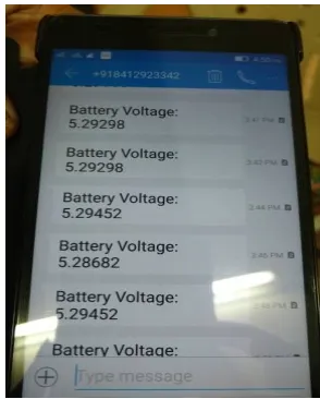
Figure 5.Battery Voltage Status.
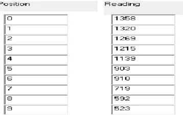
Above figure 6. shows all the Solar readings from 1st position to last position. In which at 0 position, its showing large Intensity of solar panel and at 9 position its showing less intensity of solar panel.
Figure 7.Message send and displayed on mobile
Above figure shows the initial battery voltage and the battery voltage taken after 10 seconds.Whatever status of the battery after every 10 second, the message is send on mobile with the help of GSM module.
VII. CONCLUSION
In this system, tracking of solar energy is facilitated also the voltage across panel is observed on web using Raspberry Pi (ARM11). It gives real time update of the voltage across the panel. It gives the real time Voltage characteristics of solar panel and battery with respect to time.
In this system, MPPT algorithm is implemented for tracking the solar panel to get maximum energy for the Sun. The system measures the voltage across the solar panel and plots relationship between voltage across panel with respect to time. When battery will be fully charged then system sends SMS on mobile. The system also shows status of battery charging on monitoring system. Thus purpose of Maximum Power Point Tracking algorithm is achieved successfully.
REFERENCES
[1] Q. Li and P. Wolfs, “A review of the single phase photovoltaic module integrated converter topologies with three different DC link
configurations,” IEEE Trans. Power Electron., vol. 23, no. 3, pp. 1320–1333, May 2008.
[2] L. Cristaldi, M. Faifer, M. Rossi, and S. Toscani, “MPPT definition and evaluation: A new model-based approach,” in Proc. Int. Instrum.
Meas.Technol. Conf., 2012, pp. 594–599.
[3] L. Cristaldi, M. Faifer, M. Rossi, and S. Toscani, “A simplified model of a photovoltaic panel,” in Proc. Int. Instrum. Meas. Technol. Conf., May
2012, pp. 431–436.
[4] T. Esram and P. L. Chapman, “Comparison of photovoltaic array maximum power point tracking techniques,” IEEE Trans. Energy Convers., vol.
22, no. 2, pp. 439–449, Jun. 2007.
[5] J. H. Lee, H. Bae, and B. H. Cho, “Advanced incremental conductance MPPT algorithm with a variable step size,” in Proc. 12th Int.
PowerElectron. Motion Control Conf., Sep. 2006, pp. 603–607.
[6] P. Sanchis, J. Lòpez, A. Ursùa, E. Gubìa, and L. Marroyo, “On the testing, characterization and evaluation of PV inverters and dynamic MPPT
performance under real varying operating conditions,” Progr.Photovolt., Res. Appl., vol. 15, no. 6, pp. 541–556, Sep. 2007.
[7] N. Femia, G. Petrone, G. Spagnuolo, and M. Vitelli, “Optimization of perturb and observe maximum power point tracking method,” IEEE Trans.
Power Electron., vol. 20, no. 4, pp. 963–973, Jul. 2005.
[8] M. Koehl, M. Heck, S. Wiesmeier, and J. Wirth, “Modeling of the nominal operating cell temperature based on outdoor weathering,”
Initialize The Solar panel Position to default (1st position)
[9] M. Catelani, L. Ciani, L. Cristaldi, M. Faifer, M. Lazzaroni, and P. Rinaldi, “FMECA technique on photovoltaic module,” in Proc. IEEEInstrum.
Meas. Technol. Conf., May 2011, pp. 1717–1722.
Flow Chart of Voltage Based Peak Power Tracking.
Above figure shows flow diagram for the MPPT algoritham of Voltage Based Peak Power Tracking is used. Which shows the total working procedure of MPPT algorithm.
A
No
Yes
Is time= 30 seconds?
Select channel 1 OF 12 bit ADC Read ADC Store and display the battery voltage send the Battery voltage to PC via Wi-Fi.
Is time= 2 Minutes?
Move the Solar panel to 1st position Read the Conventional reading and send to PC
Select channel 1 ,Read ADC, Send the reading of position=1 to PC
Move Solar panel to next position
Is position =10?
Calculate the position of Maximum Solar voltage
Move Solar panel to the Maximum Solar voltage position No
No
Yes