Self - Centering Behaviour of Post – Tensioned
Dual Shell Column under Seismic Loading
Prince Jo Mathews1
P.G. Student, Department of Civil Engineering, SCMS School of Engineering and Technology, Vidhya Nagar,
Karukutty, Ernakulam, India1
ABSTRACT:Current provisions for seismic design of bridges allow columns to respond beyond the elastic limit under
the design earthquake, and to be damaged provided that collapse is prevented. Various studies were conducted to make structures earthquake resistant. But no one was able to make a perfect earthquake resistant design technique. An earthquake at the epicenter or at places nearby can cause catastrophic damage to structures, loss of life and injuries to occupants. There was a clear need to develop innovative and seismically resistant approach. Such an innovative technology was found with the use of Self - Centering Precast Concrete Dual Shell Column. The seismic performance was investigated by modelling this column using ANSYS and studying the hysteretic behaviour. Also post-tensioned Concrete Filled Steel Tube and Reinforced Concrete Columns were modelled to study their seismic response.
KEYWORDS: Self-Centering, Energy Dissipation, Hybrid Rocking, Post– Tensioning, Hysteretic Behaviour.
I.INTRODUCTION
There are a large number of bridges, dams, etc., throughout the world in need of repair or replacement to resolve structural or operational deficiencies. Current seismic design practice is to make the structure rigid and behave as a rigid system. It doesn’t take into account the long-term use following an earthquake. The system is therefore built with regions that will be sacrificed during moderate and strong earthquakes and may require from minor to expensive repair work. In addition, the occurrence of severe damage or partial collapse of a bridge system can lead to critical consequences. There is a clear need to develop innovative, seismically resistant approaches to replace these deficient structures while minimizing the impacts to the public, environment and workers.
As a consequence, research efforts have been prompted into advanced technologies that reduce residual damage to the main structural elements, and encompass self-centering properties which allow the structural system to return to its original position after an earthquake. Moreover, these innovative solutions need to be economically viable when compared to existing technologies. Various systems were developed which include “Self-Centering R.C.C walls”, “Self-Centering Steel Plate walls”, “Self-Centering Precast Concrete dual shell column”. Use of precast members, replacement of traditional time-consuming reinforcing cages with steel pipes, and adoption of hollow cross-sections resulting in weight reduction, are aimed to improve constructability and to reduce on-site burdens. In parallel, the combination of unbonded post-tensioned joint connections with specific energy dissipating devices ensure seismic resilience, in the form of self-centering capability, facilitation of structural fuse repair, and minimization of damage to the main structural elements. As a consequence, traffic impacts, environmental disruptions, and life-cycle costs can be reduced, responding to an initiative bridge column technology.
II.RELATED WORK
failure of stirrups, dual – shell column with internal dissipator failed due to buckling of these dissipators. The structure was still able to withstand axial loads. The structure required cutting of external shell of column and replacement of dissipators to bring back the structure to its full use.
Restrepo J. I.et al. [1] (2014),conducted a study on “Seismic Behavior of Post-tensioned Self-Centering Precast Concrete Dual-Shell Steel Columns”.In his study, he found the effect of providing external devices. In my study, I have used eight number of dissipators and also conventional reinforcement and studied the seismic response.
III.CONSTRUCTION DETAILS OF DUAL SHELL COLUMN
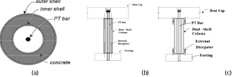
The system developed combines a precast concrete hollow-core column with on-site post-tensioning and supplemental energy dissipation. The column consists of two concentric cylindrical steel shells with concrete sandwiched in between, as shown in Fig. 1. The outer shell acts as permanent formwork, and provides longitudinal and transverse reinforcement. The inner shell also behaves as permanent formwork, and prevents concrete implosion under large compressive strains. Hollow-core section reduces self-weight and constructability is enhanced by the use of a precast element without a reinforcing cage. Gaps are allowed to open in tension under severe lateral displacement demand, and to close subsequently upon load reversal. Self-centering/rocking properties are provided by gravity forces and one or more unbounded post-tensioning (PT) bars, designed to respond elastically. Special connectionsare provided between column, bent cap, foundation, and PT bars which allows easy replacement of bar, during corrosion or in case of other damage to the bars. Energy dissipation takes place through extensive yielding of internal dowel bars as shown in Fig. 1(b), or external devices as shown in Fig. 1(c), preventing the main structural members from suffering significant damage. Under a strong intensity shake only these devices are expected to undergo multiple cycles within the inelastic range of response, with possible need of replacement, but the structure is expected to remain functional overall.
(a) (b) (c)
Fig. 1. (a) Plan of Dual-Shell Column (b) Section of Internal Dissipator System (c) Section of External Dissipator System
IV.OBJECTIVE
1. To study the seismic behaviour of Post - Tensioned Concrete Filled Double – Skinned Steel Tube (CFDSST)
column in the presence of internal and external dissipators analytically.
2. To study seismic behaviour of Post – Tensioned R.C.C columns and ordinary Concrete Filled Steel Tube (CFST) columns.
3. To determine the Load – Displacement response of these columns.
V.METHODOLOGY
1. Modelling Post – Tensioned CFDSST columns with dissipators in ANSYS.
3. Validating the model.
4. Obtaining the result and predicting the behaviour.
VI.SCOPE OF PROJECT
In traditional seismic design practices, structures either yielded or failed completely. Structure immediately loses its usability after an earthquake. Thus there was an urgent need for a more resilient structure.
VII.ANALYTICAL STUDY
Analytical study consisted of four specimens. They were:
Conventional Hybrid Column
Concrete Filled Pipe Specimen
Dual-Shell Column with Internal Dissipator
Dual-Shell Column with External Dissipator
These specimens were modelled using ANSYS Workbench and their response under seismic loading was studied.
The model dimensions were chosen from thesis work by Dr. Matthew Joseph Tobolskiet. al.on his experimental study,
and Restrepo J. I. et. al.on his work using external dissipators.The table below shows the general dimensions adopted for the models.
Table 1: Details of dimensions of specimen
Sl. No. Item Dimensions
1 Overall diameter of column 0.51 m
2 Height of column 0.86 m
3 External diameter of the column outer shell 0.51 m
4 Thickness of the column outer shell 6.4 mm
5 External diameter of the column inner shell 0.36 m
6 Thickness of the column inner shell 3.2 mm
7 Bent Cap Cross – Section – 0.64 m x 0.64 m
Length – 3.65 m
8 Load Stub Cross – Section - 0.64 m x 0.64 m
Height – 0.61 m
VIII.CONVENTIONAL HYBRID COLUMN
(a) (b) (c)
(d) (e)
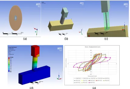
Fig. 2HYB-1 Column (a) Plan (b) Isometric view (c) Column Reinforcement (d)Deflection diagram (e) Hysteresis Response under different Loading Conditions
The preliminary stage of loading consists of application of vertical load on the specimen simulating the gravity load during a seismic event. Following the application of vertical load, lateral loading began. The first stage of loading consisted of ramping of lateral load to a specified target, i.e. force controlled control. Each loading stage consisted of three cycles of push and pull excursions. Upon completion of the force controlled loading cycles, the model was loaded to target drifts, i.e. displacement controlled control. The deflection values corresponding to load controlled cycles are found to be very small. The specimen was not found to fail and the analysis procedure was lengthy to determine the failure load. So the test proceeded with displacement controlled cycles.
There was considerable jump in load-displacement response with increase in loading and also between cycles.Upto 3% drift ratio, variation between different cycles of loading is small because plastic deformation is negligible. At 4% drift ratio, mortar bed starts crushing. Thereafter, considerable difference in hysteretic response was found. At the first cycle to 8% drift ratio, the column fails due to failure of stirrups.
IX.CONCRETE FILLED PIPE SPECIMEN
(a) (b) (c)
(d) (e)
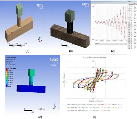
Fig. 3HYB-2 Column (a) Isometric view (b) Meshing (c) Displacement controlled loading protocol (d)Deflection diagram (e) Hysteresis Response under different Loading Conditions
There was considerable jump in load-displacement response with increase in loading and also between cycles. Upto 3% drift variation between different cycles of loading is small because plastic deformation is negligible. At 4% drift ratio, mortar bed starts crushing. Thereafter, considerable difference in hysteretic response was found. At the second cycle to 8% drift ratio, the column fails due to failure of stirrups.
X.DUAL - SHELL COLUMN WITH INTERNAL DISSIPATOR
The dual shell specimen (also referred to as HYB-3) utilities a steel pipe for confinement and lateral reinforcement and an inner corrugated steel pipe to form an inner void and prevent implosion of the concrete section. The use of the outer steel pipe provides enhanced confinement while the inner pipe allows for the creation of a hollow section which can reduce the section weightThe general sectional dimensions are identical to the conventional hybrid specimen.
cap, the column rebar is terminated. The number and mechanical properties of post-tensioning bars and rebars were chosen identical to that of HYB-1 Column.The post-tensioning bars are set inside a PVC pipe. The smooth HDPE pipe will not provide significant bond and is expected to debond during seismic actions such that the tendon acts as if completed debonded over the length.Cementitious Material properties and Loading Protocol was similar to that of HYB-2 Column.
(a)(b) (c)
(d) (e) (f)
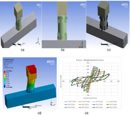
Fig. 4HYB-3 Column (a) Isometric view (b) Plan of ducts for PT-bars and dissipators(c) PT-bars and dissipators(d)Static boundary conditions (e)Deflection diagram (f) Hysteresis Response under different Loading
Conditions
There was considerable jump in load-displacement response with increase in loading and also between cycles. Upto 3% drift ratio, variation between different cycles of loading is small because plastic deformation is negligible. At 4% drift ratio, mortar bed starts crushing. Thereafter, considerable difference in hysteretic response was found. At the second cycle to 8% drift ratio, the column fails due to buckling of internal dissipator.
XI.DUAL - SHELL COLUMN WITH EXTERNAL DISSIPATOR
welded to outer shell of column. Details of this column are identical to that of HYB-3 Column. Cementitious Material properties and Loading Protocol was similar to that of HYB-3 Column.
Eight external, buckling-restrained, energy dissipators were incorporated and radially distributed around the column perimeter. These devices consisted of steel bars with a reduced diameter over a specific length. Each 343 mm long steel bar had an original diameter of 25.4 mm, which was reduced to 14.3 mm in the 165 mm long milled portion. Grade 1018 A576 steel was used for these devices. The milled part was encased within a steel pipein order to prevent buckling. The external dissipators were attached to anchors within the footing and to the column outer-shell brackets.
(a) (b) (c)
(d) (e)
Fig. 5HYB-4 Column (a) Isometric view (b) Vertical Section (c) Meshing (d)Deflection diagram (e) Hysteresis Response under different Loading Conditions
XII.COMPARISON OF RESULTS
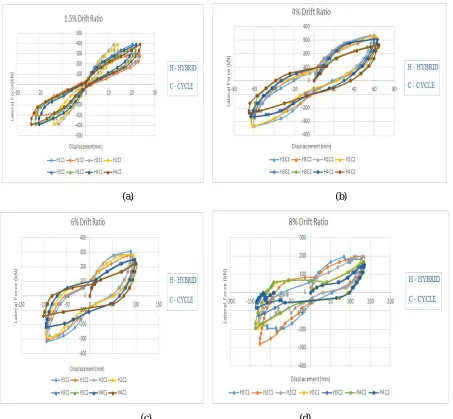
Comparing the hysteretic response of all four specimens, no significant variation was seen during initial stages of loading. Upto 3% drift ratio all specimens behaved with very small plastic deformations. At 4% drift ratio, mortar bed failed by crushing. Beyond 4% drift ratio, specimens showed large plastic deformations and all specimens were found to fail at 8% drift ratio. But, in specimens with internal and external dissipator, columns fail due to failure of these dissipators without any significant structural damage. The structure can still take axial loads. The following figures show the comparative hysteretic response.
(a) (b)
(c) (d)
Fig. 26. (a) Comparison of Hysteretic Response at 1.5% Drift Ratio (b) Comparison of Hysteretic Response at 4% Drift Ratio (c) Comparison of Hysteretic Response at 6% Drift Ratio (d) Comparison of Hysteretic Response at 8%
There was very large difference in hysteretic response of different specimens and also between cycles. The HYB-1 specimen fails under first cycle to 8% drift ratio due to failure of stirrups. HYB-2 specimen also fails due to failure of stirrups but under second cycle to 8% drift ratio. HYB-3 and HYB-4 specimen fails under second cycle to 8% drift ratio due to failure of internal and external dissipators respectively but with no significant damage to actual column. The structure can be reused with replacement of damaged components, which can be done at a relatively low cost as compared ordinary reinforced concrete column
XIII.CONCLUSIONS
The use of Dual-Shell Column satisfied the need for a resilient structure to seismic loads. Comparison between experimental and analytical responses validated the models and also proved its applicability. Based on the analytical study following conclusions can be made:
1. Up to 4% drift ratio, all the hybrid columns were able to self-center with negligible residual drift.
2. Upto 8% drift ratio, dissipators were able to reduce seismic load transmitted to structure and also rock back with some residual displacements, while the structure can still take axial loads.
3. The structure can be easily made to its full use with some minor repairs.
4. The use of internal dissipators in the form of longitudinal dowel bars, crossing the column footing interface, offers the advantage of avoiding aesthetic interference.
5. However, for inspection and replacement of damaged dissipators would require cutting and repairing the outer
steel shell: for this reason, accessible external devices could be advantageous. 6. Mortar-Bed degradation resulted in significant reduction in system’s lateral capacity.
7. The adoption of post-tensioning bars instead of strands allows for re-tensioning or de-tensioning and replacement, in case of damage.
8. Bars can be unscrewed from the foundation anchorage and substituted together with the grouted ducts which
protect them from corrosion.
9. Future Scope - Improvements in strength can be made by adding poly-propylene fibers to mortar- bed or by
replacing with neoprene pads.
REFERENCES
[1] AthanassiosVervelidis, Gabriele Guerrini, Restrepo J. I., and Milena Massari, “Seismic Behavior of Post-tensioned Self-Centering Precast Concrete Dual-Shell Steel Columns”, Journal of Structural Engineering, ASCE, vol. 14, pp.1-11, 2014.
[2] Mathew Joseph Tobolski, “Improving the Design performance of Concrete Bridges in Seismic Regions”, Thesis -eScholarship, UC San Diego, 2010.
[3] Caltrans, “Seismic Design Criteria”, California Dept. of Transportation, Sacramento, California, USA, 2010. [4] Gabriele Guerrini and Restrepo, J. I., “Self- Centering Precast Concrete Dual Shell Steel Columns”, vol.15, 2012.
[5] Guerrini, G., and Restrepo, J. I., “Advanced Precast Concrete Dual-Shell Steel Columns”, 8th International Conference on Urban Earthquake Engineering, Tokyo, Japan, vol.1, pp.1125-1129, 2011.
[6] Lam. N. T. K., and Tsang H. H., “Seismic Drift Demand and capacity of Non-seismically designed Concrete Buildings in Hong Kong”, eJSE International Journal, pp. 110-121, 2008.
[7] Mathew R., and Nathan Brent Chancellor, “Self Centering Seismic Lateral Force Resisiting System: High Performance structures for the city of tomorrow”, Buildings, vol.4, pp.520-548, 2014.
[8] Holden, T., Mander, J. B., and Restrepo, J. I., “Seismic Performance of Precast Reinforced and Prestressed Concrete Walls”, Journal of Structural Engineering, ASCE, vol.3, pp. 286-296, 2003.
[9] Andre Filiatrault, Jose Restrepo, and ConstantinChristopoulos, (2004), “Development of Self-Centering Earthquake Resisting Systems”, 13th
World Conference on Earthquake Engineering, Vancouver, B.C., Canada, vol.1, August, 2004.
[10] Matt Rouse J., Sarah Billington I., and Won Lee K., “Damage Estimation of Self-Centering Precast Concrete Bridge Pier System using a Performance-Based Assessment Methodology”, 13th World Conference on Earthquake Engineering, Vancouver, B.C., Canada, vol.1, August,
2004.
[11] Amar Rahman, Restrepo J. I., “Seismic Performance of Self-Centering Structural Walls Incorporating Energy Dissipators”, Journal of Structural Engineering, ASCE, vol.133, November, 2007.
[12] Daniel Dowden M., Michel Bruneau, and Ronny Purba, “Behavior of Self-Centering Steel Plate Shear Walls and Design Considerations”, Journal of Structural Engineering, ASCE, vol.138, January, 2012.